


Gus Potter
-
Posts
2341 -
Joined
-
Last visited
-
Days Won
29
Everything posted by Gus Potter
-
The public information is the key plus you need to go to the council and library archives and possibly pay for a search on what if any consented alterations have been made to the house next door. You may find that the neighbours have made unauthorised alterations and that may explain their reluctance to engage. How deep have you delved into the public records? I always advise to play something like this off a straight bat. Go right back and make sure you have all the basic facts correct. It sounds brutal but if they have made alterations without consent then these don't count.. just don't warn them in case they get restrospective consent before you get your submission in.. Once you establish that you are on a sound footing and you work from there. The right to light calculations are complex when close to a boundary and they vary depending on how your project will impact on say a utility room next door or a bedroom / habitable space often called an office but still a habitable apartment. You also have over shaddowing that applies to say external spaces and privacy.. looking into their windows. This requires diplomacy as you are going to have to live next door and you don't want to fall out big time in an ideal world.. but you if you can establish what you are entitled you have a basis on which to negotiate your way ahead..as you have other things to deal with as follows.. Can you post the soil investigation report and a plan of the site showing where the tree is? What is the height of the tree, what is the trunk diameter 1.0 m above the ground, how far does the canopy extend, what is the orientation of the site in relation to the tree. It's important to understand where the tree gets it's structural support to resist the prevailing wind and nutrients from.. (which could be from a diferent direction). Then you can take view on where the roots grow and the impact it will have on your founds. Your SE is playing safe and sticking to the BC and NHBC guidance.. probably because you have not paid them enough to look at this in greater detail. Pay them an extra five / seven hundred quid to sort this out, provide a bespoke Engineering solution for your site and they could save you thousands. A bespoke solution would require your SE to have sufficient expertise in this area which not all SE do have. Can you cut the tree down and wait 18 months before building?.. a brutal approach but we are taking money here and not one I would advocate as a first option.. but if the tree is old / diseased that may be the best approach. You could go to an Arborist for a tree report that covers root propegation and life expectancy of the tree.. why adopt a complex found design if the tree is on it's last legs.. trees die like all of us! I think your SE is being cautious here as probaby does not have a lot of info to go on. Work on the premis that you'll need to some PWA notification, don't let this drive your initial design assumptions. Any pile or found that adds significant extra stress to ground you don't own basically requires consideration under the PWA. Screw piles do indeed mitigate the need for deep excavations.. but they come with potentially significant problems later on.. there is no free lunch. I would go for the simple stupid type found, get a handle on the tree, gather the facts on the neighbours position in terms of light, don't panic and take it a step at a time.
-
The concept is great. For example there are folk on BH that have large plots.. access to excavators as part of their day job, space to dump the muck away and so on and this could make things cost efective. On a small scale I have UF in a structural concrete slab on a well insulated perimeter wall. I know I'm heating the dumpling of clay soil in the middle of the house.. like a battery.. I notice it as going into winter we need to pump in a bit of heat to dry out the concrete slab above the insulation.. and warm the dumpling below.. it takes about a month to settle and after that all things being equal the energy input drops off. As on clay there is no ground water flow that carries the heat away. I'm sure I have some kind of low temperature battery / heat store .. just can't prove it.
-
Good to see you making progress. Hope this helps. As you are doing this yourself you are probably doing a good job.. getting levels etc right. I like your roof build up spec apart from "the massive firring pieces" and a vapour barrier to the underside of the joists. Your joists are in the warm envelope.. why the vapour barrier.. maybe best to let any water vapour that condenses in the joist depth zone just re evaporate and come back into the room? Anyway by the time you paint the ceiling it will be failrly impervious anyway so will resist most say steamy bouts that may occur in a say kitchen area? Ok now the structural side. These types of roof are pretty light weight so don't deflect that much under normal conditions.. so under these loading cases your 225 Posi joists won't deflect / creep that much. Practically under their self weight they will dish a bit in the middle as you would expect. When you lay them examine each one as the won't be straight.. put the bendy side upwards.. like a pre camber. On the top side of the drawing this will be fine but you may trap water behind the kerb at the bottom of the drawing. An easy way of sorting this out is just to add some extra GRP layers on the top / high side (bottom of the drawing) to give you local fall so the water / snow melt does not get trapped behing the kerb at the bottom of the drawing. Once you build it and put the spirit level on it you'll see where you need to build up locally... this you can do with GRP but not say as easily and well with EPDM or PTFE membranes. It looks like you have potential for snow drift loads, snow being driven against a higher parapet wall and falling onto the flat roof or falling off a higher roof onto the flat roof etc. I think your SE may have clocked that hence the joist size.. so you can go back to BC if asked and say my SE has accounted for the loads so can use a shallower gradient... 1:80 For all it's not just the extra weight of the snow but the fact that snow blocks the drainage routes up that causes the problem.. it's that wet snow / rain you get.. it clogs everything up and is heavy.. not like powder snow you ski on... it's just nasty. Now it looks like your SE has sized everything up properly in terms of joist size thus you can use the finished fall of 1:80. Roof length / 80 fall is 4940 / 80 = 62mm fall. But this requires a configuration of firring pieces that will be 62mm thick at one end tapering to zero..! This means that you have to cut each firring piece to a different depth, to a close tolerance and fix it to the top of each joist.. which the merchants are not keen on supplying as each firring piece is bespoke. Where the firring pieces are thin you use longer fixings and glue... the glue is important as is allows transfer of the forces in the roof to the walls. called diaphragm action.. long fixings tend to bend so we need the glue to properly bind the firring to the tops of the joists.. like a Glulam beam. The thin firrings are just packers. You need 40mm screw penetration into timber so as soon as the firrings are less than 40mm thick you need longer fixings that go all the way and at least 40mm into the posi joists flanges. @Russdl has done something similar as has height and thickness constriants. I hear he cut the firring pieces on site with a Skill saw, got them spot on and made a saving... even put a bevel on them as the top side of the firring piece needs a scuff to follow the plane of the roof as it slopes perpendicular to the firring piece. In summary.. maybe @Russdl will let you know how he did it... with varying depth firring pieces tapering to effectively zero.. which could solve your dilemma. In other words you roof fall will be 62 mm. At the high end the roof will be 62mm higher. If you end up with only 100 mm upstand at the bottom of the drawing this should work if you seal it all up well as you have not got potential snow drift build up or wind driving the rain up the wall as it is on the leeward exposed side?
-
As if you probably don't have enough on your plate below is a link to Polypipe https://www.polypipe.com/housing/above-ground-drainage-faqs Which says... "Can below ground PVCu drainage pipe or fittings be installed for above ground sanitary pipework? Below ground PVCu drainage pipe and fittings can only be used underground, they are not manufactured to the correct standards or material formulation for above ground applications, Building Regulations Part H state that PVCu materials for above ground gravity sanitary pipework should be to BS EN 1329" Below ground pipes tend to be brownish. In terms of internal or external pipework.. internal pipework is fine, specify this often.. but recognise that at some point someone is going to put something daft down the toilet or a lot of fat or a decorator is going to wash out some fast set or Polyfilla down the sink. So long as you think about.. where will the blockage occur and make sure you can rod the drain form one end or the other. What you don't want to do is have big access hatches in your nice decor / tiling or other finishes.
-
Thanks for the appreciation.. but practically and on site when the pressure is on.. the sequencing of works could fry everyone's brains.. and if it "forgotten" about it could cause havoc later on. Mind you this is the advantage of self building and keeping an element of control.. if you put the work in early and understand what you need to do and when then you can tackle the whacky and present it as simple to the builders.. which helps stops them adding on daft costs. I can see this might suit the home automation folks on BH.. its a free duct (apart from the fabrication of the cap and notching at the base) so can you put something in it!
-
I wonder if they have hidden the rainwater pipes inside the columns? The cap plate at the top would be like a polo mint.. at the bottom the pipe exists via vertical slot or something along these lines. Would be interesting to see if that works structurally, probably would as the loads are pretty low if using say a 10 inch circular hollow section.
-
What great posts from all, you all get a "like from me". I used to say when I was a main contractor. If you PM on a self build and work hard you can save 10 - 15% on the build cost. The posts above are great as they show you how you have to adapt and wear lots of hats.. build relationships, network, learn to deal with suppliers, getting let down and go through a big technical learing curve so you know that what you see getting built is right and complaint. There is no free lunch, it takes hard work. However if you put your back into it big savings can be made that are tax free. One big thing is you can do overtime at work, earn extra, save and pay someone else to do it all. But you get whacked for income tax on your extra earnings. Or you can spend less time at work and work on your build.. you'll actually have to work much harder.. but it's for you so you don't log the hours spent, the personal sense of achievement can't often be quantified in monetary terms. The main thing is that you get that quite satisfaction of doing it yourself.. few folk in the UK ever experience this so grab the opportunity and go for it. There is an old saying .. folk that work hard often get lucky!
-
Pretty much all of them.. that is one reason for self building.
-
Beam helper on stair stringer
Gus Potter replied to MortarThePoint's topic in General Construction Issues
What a tidy job.. well done. Those birds mouths at the bases of the stringers look great! The weak spot is at the top as you are fixing into the end grain where the notches for the treads can split off. Follow the load path which is.. each tread is on a non continuous piece of timber to some extent... the notched part. The notched part transfers the load to the main continuous part of the stringer. At the top you have three fixings into the end grain, probably only two of these are really doing the work, hard to tell. Assume that at some point the timber will split to some extent. If you plate the outside stringer with ply and glue any potential problem should be mitigated. The ply will also give you a good stable background to glue / fix the facing timbers.. in other words you kill two birds with.. Fantastic! Can you post more photos as you go to let folk see the results. It's a great way of doing it if executed well. You have spent the time making the underlying structure stable at low cost.. now you get to play with the high end finishes.. which should be cheaper comparitively as they are non structural.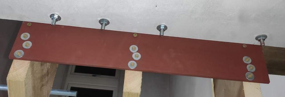
-
Nearby Piling, advice needed!
Gus Potter replied to Residential build's topic in General Structural Issues
Lots of good advise from folk on BH. Excuse the spelling and grammer. Hypothetically if you came to me I would take a different approach. Yes I know we have the party wall act etc. But why focus on that as you main stay of arguement. The PWA( England) and the law in Scotland is not strong and has a lot of gaps that can be exploited, a weak spot is ground water, flows, head and flow paths. Lets take a few steps back. You have an old house, the original part circa 100 years. I doubt it will be sitting on the sedimnetary bedrock (Greensand). In fact it surely can't be as you have an extension with 1.0m deep founds... I suspect that the extension found depth is driven by standard foundation rules from BC that applied at the time. In other words your house and extension are sitting on a layer of different soil that is underlayen by Greensand. The soil you have under is proved so far to be adequate. Now ask.. why are they next door piling down to the Greensand. I suspect it is because they want to put more load on the ground compared with the load your house is applying to the layers of soil above the Greensand and it is not working for them.. so they are piling. Now as your house is probably "floating" on the softer layers above the green sand then you need to look at what could pose a risk later. Yes you have some vibrations but for me I would want to look very carefully at how they are going to drain the site next door and if that will change the level of the ground water that could result in damage to your house. Now that sounds all a bit abstract.. but if you got me round I would hammer the developer for information on things like this and say.. your are being unsafe.. I'll report you to HSE and all the other bodies if you don't give me the information..that I need to execute my responsibility for public safety. I do a bit of Claims work against say the NHBC and major developers. They are masters at deflecting, threaten legal action.. but when you hit them on structural safety.. they have no clothes! -
Thanks for that tip. Every day is a school day. I'm off to think about that and put that in my book of learning. Scary thing is that the older you get the more you realise how much you don't know!
-
Beam helper on stair stringer
Gus Potter replied to MortarThePoint's topic in General Construction Issues
Hello all and @MortarThePoint hope all is good at your ends. There is plenty here to look at from Mortar's photo. My thoughts are this. Start with the Architectural appearance. Not sure if you are going to clad the stair like the Americans do in a high quality stable timber.. can look great and a I'm big fan of that when I get the chance... but you need a stable platform (not too shrinkable soft woods) to do this. The overall perpendicular distance from the nose of the tread to the underside of the stringer doesn't look too bulky.. do you really want to add extra material to the underside? How will that look compared with the rest of the hall we can't see? Structurally stairs are bit different as essentially they are two beams (the stringers with treads linking the tops) spanning a gap but are at an angle. The stair you have looks pretty close to the 42 deg maximum allowable pitch. Just say it is 45 degrees for ease of demonstration. Some of the basic checks we do when designing a stair is to make sure the treads (these are flat horizontal beams) are strong enough to span between the stringers, then we check the stringers and then the connections at the top and bottom of the flight. But as the stringer is at an angle we take the downwards load and convert that into it components which are a load acting perpendicular to the stringer and an axial load. The above shows the green load (you and your pals) on the treads converted into the component (vector) loads. Basically the bending force on the stinger is reduced by about 30% so that is good news as timber is very good at carrying axial loads along the grain. But what we are trying to do is get a stair that is not bouncy as well as not falling down. Beams (stringers in this case) bend in two ways.. in their plane and also by twisting.. as soon as they twist they deflect more and loose stiffness so bend even more... and then things often just get worse from there on. For BH folk! One thing to recognise here is that you can walk up a stair and feel movement.. highish frequency = "twangy" as opposed to low frequency which tends to make you nervous. My personal view.. it's actually a good feeling on a domestic stair as I think it gives it life. It "twangs a bit" but still feels safe and comfortable to walk up... that's my view for houses. You spend all that money on say other parts to bring the house to life.. why not let the stair resonate with you as you move about the house? Take a high end example say an oak frame.. it's living and moving.. why not make the stair feel "alive" My self build had a "lively stair" and it felt great.. but was still safe. I other words you can over design and make a stair dead both Architecturally and dead in terms of having a responsive house. Compare this with the stairs you go up in sports stadiums (I hope) they feel solid and dead.. but for good reason. What would you choose? Anyway back to strength and stiffness. If you take the stringers in isolation they will be quite flexible and bounce about. But the key thing is how the treads are fixed to the top of the stringers as it is mainly the treads that prevent the stringer form twisting... and thus misbehaving. The weak spot is.. and I think you have clocked this is that when the stringers dry and treads shrink they will split the stringer along the line of the bottom of the stepped notches. Now you lose all the stiffening etc that the stair relies upon. I think the split will start on the outside of the stringer away from the wall due to the treads shrinking and the way they bend.. they cause inward rotation so the split should start on the outide face of the stringer. If it was my stair I would get some 18mm marine ply and template that to the photo of the stringer away from the wall. Then glue and screw that to the stringer with structural glue say Cascamite. The screws only act as clamps while the glue sets. That will do two things. Main thing is it stops splitting of the notched bit away from the main body of the stringer.. so the tread still stops the stringer from twisting.. and the ply will also act to resist the some of the bending forces not least as you have effectively thickened the stringer. Lastly though you need to check the supports at the top and bottom of the flight. @markc As a ball park figure a domestic stair is generally desigend to carry about 150kg/ square metre on plan plus a safety factor of 1.5 to 1.6. Say 260 kg on plan to allow for a bit of self weight of the stair. Some of that will get transfered to the inner stringer fixings.. but just check your supports at the top and bottom are good enough. Hope this helps you make an informed descision. Main thing I want to know is how you are going to finish the stair, hand rails, glass? Just to add a caveat.. make sure you don't compromise fire protection etc! You may need to line the bottom of the stair?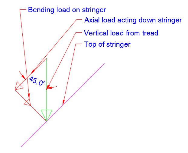
-
Location of steels and insulation
Gus Potter replied to Tetrarch's topic in House Extensions & Conservatories
Yes you are spot on. There is not much to go on in terms of the plan you posted.. but it looks like you have big open plan areas on the ground floor at that point thus horizontal stability is a key issue... can dominate the design at times. -
Are you saving any money or just having fun playing with the tech, just like buying an old car?
-
RSJ overlaps one side and falls short the other onto pad
Gus Potter replied to ag1976's topic in RSJs, Lintels & Steelwork
How much short? -
I would go for the pond and plan your garden and wildlife around that. Get that right and you will reap the rewards in terms of habitat and the enjoyment that follows. See once you get your hands dirty, playing with the water and clay.. making a pond.. you'll feel so good but as an adult you can admit that! but if you have kids.. it's called transferrance.. family fun all round. You can have the odd raised dry area say a deck. Try the pond thing first.. and report back.. in year or two.. it's like the outdoor nurseries where the kids and you get to be yourself.
-
Hello and welcome to BH from me. Ok you're in a conservation area. But first with my SE hat on don't dig out any more as you could compromise the founds! Post more photos and you'll get lots of help here. Main thing is not to do something that makes other things worse. But to wet your appetite attached is a typical tanking system you can install yourself.. you buy it online. Before you do you have a big learning curve ahead of you to get this right but you have made a start by posting on BH. Newton_CDM_Installation_Manual_9.0-2.pdf Newton-508_TDS_9.1.pdf
-
Location of steels and insulation
Gus Potter replied to Tetrarch's topic in House Extensions & Conservatories
You really should start asking questions.. There is a massive Elephant in the room here in that you are removing huge amounts of the building that are stopping it blowing sideways, called horizontal stability. Just glancing at your drawings.. you have building stability issues that need put to bed. That little green circle on your drawing could cost you a lot of money.. so ask what it is and the implications.. we are talking thousands here not a few quid. I work with experienced Architect's as an SE (Architectural designer myself so wear two hats) that understand this concept and communicate this to their Clients early on and how you get around it in a cost effective manner. As the Client push your Architect and SE to work together. Most importantly they should be explaining to you what they are doing, thinking and giving you info to let you make informed decisions. -
Raise ground floor level in an old church
Gus Potter replied to Jimbobjones's topic in Floor Structures
Like your post and love old buildings like this. What you propose is also easily reversable, you're being a good custodian. I would give the EPS a miss and spend a bit more on 150mm thick PIR for the following reasons: 1/ Your concrete floors probably will be well off the level and you will spend ages getting this right. 2/ EPS particularly Jablite compresses a lot before it carries the declared load... localised loads around shower trays / brittle finishes etc 3/ The labour time in fitting three layers is hard going. In summary by all means float your floor but I would not use Jablite or similar.When floating a floor use loads of glue and have some concrete blocks etc to hand to weigh it down while the glue sets. Leave a gap round the edge of the floor for movement. Do one room first and see how that works in terms of your costs and time.. best to do it yourself if you can as you often get a better job. Say you have the 10" (250mm) as the least thickness. What about using (100mm thick layer) type 2 sub base.. it is often what we call plastic but we can use this to our advantage.. this binds together quite well with a whacker plate ( moisten if need be with a light spray of water), blind that with a bit of soft sand. The reason for the soft sand is that the insulation is often not flat.. has bows in it so the only dead weight you have to hold it down is the T&G flooring.. you'll get a bouncy floor. You can sweeten out the sand blinding a bit and bed the insulation to some extent. For greater depth just increase the depth of the type two. If you have a shower tray, often in the corner of the room then you can fix a batten with DPC behind to the wall to support the edge of the flooring.. yes not ideal but it will stop the floor dropping and the shower tray leaking. You can run water pipes and waste pipes in the insulation and in the blinding layer.. but avoid electrical cables unless in a duct. I have cables in my UFH concrete floor but they are in ducts and the heating pipes are kept away from the cables. In terms of BC. Strictly speaking you are adding load to the floor but if pulled up you could probably justify it is ok. Some things but not all.. I would check are: 1/ If raising the floor will that mean some of the glazing is now below 800mm if so glass needs to be safety glass or have protection. 2/ Do you have any stairs.. are you going to make the rises uneven and cause a non compliance? 3/ Is there anything you have not told us in terms of how the walls breathe? Be aware that when you introduce insulation to an old building it can shift dew points etc.. best to just check before carting on. One main thing is to put in plenty perimeter insulation.. I would try and go for 50mm and take this right down to the existing concrete floor. If you keep the dumpling of soil a bit warmer inside the external walls this will deliver a surprising benefit. you can see the effect this has to some extent when you look at the U value tables for insulated solid floors.. it's called the perimeter vs area ratio.. a lot of heat is lost around the perimeter. -
Building Soul - with Thomas Heatherwick.
Gus Potter replied to SteamyTea's topic in Research Resources
Thanks @SteamyTea will give this a listen. -
Have you considered stick building a timber frame.. you do the walls and either a cut timber roof or prefabricated trusses? Stick building has plenty of advantages.
-
Victorian cellar conversion. Alternative to underpinning works.
Gus Potter replied to Annker's topic in Basements
I think I can see where you are coming from. Below is a simple model / sketch. Agree.. and it is often done badly.. and dangerously.. to do it well costs money.. with basements some contractors take the "who dares wins" approach, the first things that gets compromised is safety and quality of workmanship. What a good point, it's these things you would not probably know about. @Annker The theory around the sketch is well tested. This cantilever slab method is used when you have say a gap site and can't pile up against the adjacent buildings for one reason or another. The above I think results in an independent floor that doesn't impact too much on the existing founds etc. Looks simple as it's a foundation within an existing foundation... but.. the underbuilding will maybe have cross walls etc so it's not as simple as it looks as a sketch! The new strip found might cause a bit more settlement due to the extra stress on the soil but most buildings tend to fail / protest when the walls move outwards rather than inwards. In a domestic application you may just have a configuration where this is best solution, not often but sometimes.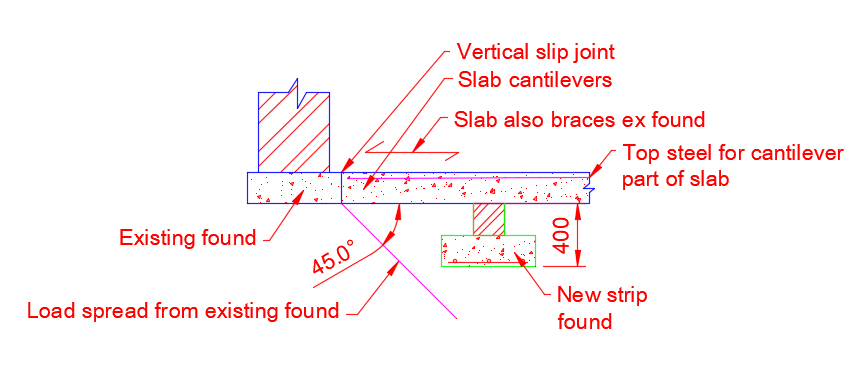
-
Best model acoustic insulation for studs and joists?
Gus Potter replied to ashthekid's topic in Sound Insulation
No wonder you are confused, I do this from time to time as the day job and suffer also. Bear with me.. The way I get my head round this is to think about how a speaker works.. an old one say one up from an Amstrad... take a step back and imagine yourself in flaired trousers.. listening to Santana you may not have been born then but.. there are pros and cons to that too.. the old days were not that great at times.. so be glad you missed it! Anyway at the bottom you had the "woofer".. a big speaker that provided the base.. If you took the cover off you could see it moving... to be able to move it had to move lots of air but realtively slowly. In the middle was a middle size speaker, you can't see this moving but it provided the middle frequencies. It moved less air back and forth but more quickly. At the top was the tweater that was a small speaker. It delivered the high frequency so moved the air a little but quickly. A light weight partition wall works in at least three basic ways. The big and low frequency air movement caused by the woofer, in the modern world equal to you having a low frequency " wind episode from your bottom" is resisted by the weight of the plaster board. The air gap takes out the high frequency and the glass wool the medium. All three layers act together to dampen their frequency response so it almost impossible to separate out each layers and tie that into the stiffness of the wal studs. As soon as you change the stud spacing (and length) any calculations need to be revised as the studs change the frequency response of everything that is attached to them.. As a starting point I would not look to save on the insulation thickness.. go for the 75mm as the labour cost to install is the same. Medium density wool will work fine at 75 mm. Go for at least a plaster board of 10kg/m^2.. but you'll find that standard 12.5mm plaster board just falls short, if in Scotland. To get round this you can use Gyproc Wall TEN or often just skim coat the standard 12.5mm plasterboard.. gives you a much better job than Ames taping. The critical thing is to stop flanking sound transmission. If you can pack the top and bottom of the wall so the sound does not get around it that will really deliver results. Just remember that if you keep making the partition more heavy it may overstress the structure holding it up. If you spend time on the workmanship this will deliver the best result. Ideally this is something you want to do yourself (fitting the insulation) as you will take the time to do it right... few builders take the time to do this the right way.. unfortunately. Lastly if you have wall sockets make sure they are not transmitting sound so insulate behind them. But before you adopt a solution just check with the spark that they are happy and don't have to uprate the cables.. Hope this helps.. keep your head up. -
Wet underfloor heating advice for extension and existing area
Gus Potter replied to dave2612's topic in Underfloor Heating
Good pointer. To expand. I think you are jumping the gun here. Before you get into the nitty gritty of loops, zones etc you need to understand how the wall fit on the floors, the solum structure and the founds below. You are introducing insulation so changing the dew point location. To be brief you could have a house with masonry walls, the internal leaf may have booby traps as it could sit on a built in timberwall plate. You may have a timber frame and indavetantly cause it to rot at the main structural supports.. that will result in disaster.. I kid you not. Post what you know about the floor zone.. if you know little.. stop what you are doing and find out! I like what you are doing have experimented myself on different houses with my own designed UF systems.. in all sort of floors, suspended etc so have been there and worn the shirt.. but the protection of the structure comes first then we get to play with the fun bit.... manifolds, pipe sizes etc. Play safe an get stuck into investigating the underbuilding. Also if you can post a floor plan of the whole house this would help.. you can have a mixture of solid and suspended floors. I have and got round this on ocasion by ducting while appreciating the prevailing wind and what is round about. It may sound like hard work but.. best to put effort in early as if you get it wrong it can be very expensive. -
Can you run rectangular ducting from the attic void under the ridge within the depth of the rafters insulate the duct then drop that down to the first floor ceiling?

