Crowbar hero
-
Posts
61 -
Joined
-
Last visited
Crowbar hero's Achievements
Member (3/5)
8
Reputation
-

replace floor/ceiling joists -am I insane?
Crowbar hero replied to Crowbar hero's topic in General Structural Issues
Sadly it doesn't allow any greater floor void for services routing (electrical and plumbing) or noise insulation, once the UFH goes in there'll be very little space left in the remaining void. -
replace floor/ceiling joists -am I insane?
Crowbar hero replied to Crowbar hero's topic in General Structural Issues
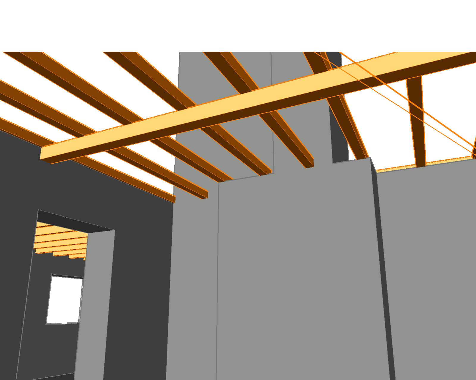
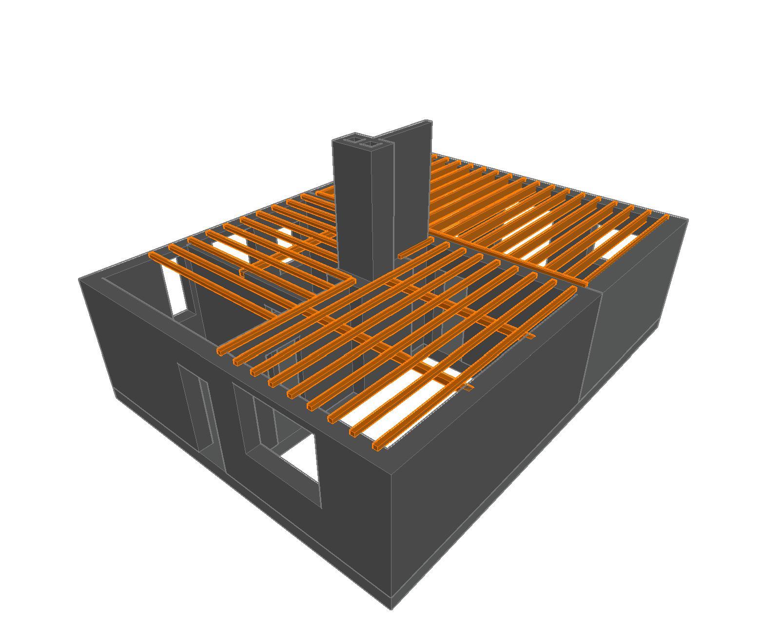
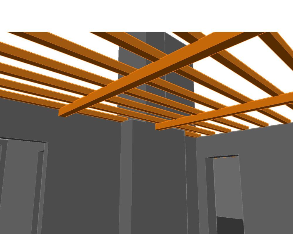
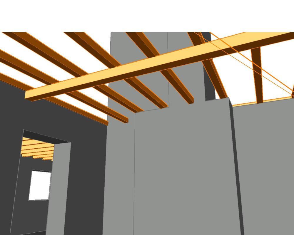
You're quite right about the transfer beam, though I'm not convinced it's steel (the only serious steel I've found so far is a lintel over an opening which turns out to be a bit of railway track), these transfer beams runs perpendicular to the obvious joists, and thus parallel to the floor-boards (which are 22mm ish). Attached are a couple of CAD sketches illustrating the estimated layout of the joists and transfer beam(s) which are about 4" deep (first floor external walls removed for clarity). Given the size and orientation of the timbers, I'm not convinced they're adding much to the party as far a lateral restraint is concerned. The structure to the rear is the extension, and obviously not part of my current speculations. One approach I'm considering is to add more timber parallel to and of a similar depth to the transfer beams underneath the existing joists. This will hopefully reduce the spring somewhat, yet allow mechanical and electrical services to pass over/under the timber without the need for notching. Added depth will allow for UFH between existing upper timber and insulation between lower (new) timbers. They can be attached to the wall with joist hangars rather than digging out fresh/deeper pockets.
-
replace floor/ceiling joists -am I insane?
Crowbar hero replied to Crowbar hero's topic in General Structural Issues
Not yet, we're still extending, and haven't gotten around to the renovation side. I like to think of the next phase when I'm designing the current as I don't end up routing linking services the wrong way.. -
there's a bit of bounce, but it's not terrible. You can walk across the a room without furniture toppling over, but if you were to jump around, you may have to reposition a few ornaments afterwards. I think the timber used back in the 30's was a bit tougher than the fast grown stuff of today- certainly of the stuff I've seen the grain is much denser.
-
House is 1930s clay brick construction with suspended timber first floor. Floor joists appear to be 3" deep, which are supported mid, and or third-span with a perpendicular 4" timber. Orientations switches from left to right side of the house. We would like to remove the chimney stack to ground level, freeing up some space (stack has been removed in the loft already), and hopefully remedying the damp issue I think is rising from it. This would leave a fair amount of floor unsupported. Am I looking at having to replace the entire floor structure? Joists/ crosmembers and boards? CAD sketches attached, first floor removed apart from internal masonry (there's one 1 internal wall that's not mad of cardboard upstairs!) the sketch is derived from various floorboard lifting and poking with a tape measure. Ground floor ceilings are 2.5m, 2.4 to the underside of the crossmember, which is an exposed (yet badly painted) feature in both downstairs rooms. Extension to the rear is shown for context, but isn't relevant to this issue.


-
had similar in an old house I rented, drain cock was via an airbrick! not an option for me this time as I've concrete floors..
-
my bad, I'll just post it to electrical as well
-
I have a horizontal run of pipework which is the lowest part of the system, so it makes sense to fit a drain cock. Given I've a choice, I could have it coming out of the pipe horizontally (on the same horizontal plane as the pipe run) or vertically (downwards, obviously). In trying to anticipate problems, I'm thinking horizontal may be preferable so that any sludge doesn't foul the thread of the retaining plug when the cock is open, but I think that's grasping at straws. Clearance isn't an issue as the area will be boxed in, so I can cope with it poking out if there are practical benefits that I've not foreseen. Could anyone share any thoughts or experiences?

-
Hi all, As part of my Home automation build I'm looking for a relatively simple scene switch (for bedrooms primarily) which can be permanently installed on the wall but can control devices via zigbee. I don't want to be changing batteries all the time, so I want mains powered (or kinetic, but I don't like the price!) This is part of a rewire so I can pull in an neutral easily enough. (In a typical scenario there'll be 3 channels being controlled: main light, bedside lamp L and bedside lamp R - i'd like to be able to control all 3 from 3 locations, the usual lightswitch point by the door, and on either side of the bed. - I've done this in the past, hardwired with 3 x 3 way intermediate switches, and it's a ball-ache). I'm seeing lots of scene switches, but very few appear to be mains powered for permanent-install, pretty much all are battery. Does such a thing exist?
-
the alarm is a "something for the future" rather than a right now job, but everything I'm working on now, I'd like to fit with an alarm in mind. This GID stuff looks interesting though G
-
Thanks all for your thoughts and comments. I'm having PIRs in a separate location to the light sources, so I don't want to be dependent on an 'all in one' type fitting (these frequently cause problems when they eventually fail too). I'm running 3C+E across all fittings and sensors so there's always switched and permanent live present - the problem with using the the switched live as an indicator of motion is the scenarios when the switched live is energized from the (non PIR) switch which is also on the circuit as an override - admittedly this would usually be in a situation when the alarm isn't set, but it does leave the installation vulnerable under certain scenarios.
-
I'm looking for a standalone external motion sensor/switch which I can use to control lighting, and also act as a perimeter sensor for a future alarm system. In an ideal world it'll have a DPST or DPDT switch rather than the SPST or SPDT switched terminal in the rear like they usually do. That way I can use one pole to switch the mains, and the other as a volt-free contact or such for an alarm interface. Does such a thing exist?
-
metal (18th ed) cable clips -not hammer in!
Crowbar hero replied to Crowbar hero's topic in Electrics - Other
I'm not sure what constitutes a good looking cable clip anyway..? I think the plastic ones are horrid. especially those that seem to have been installed by the apprentice with his shoe. Most of this would be hidden away out of sight anyway. -
metal (18th ed) cable clips -not hammer in!
Crowbar hero replied to Crowbar hero's topic in Electrics - Other
'cos I really don't like hammer in clips 😐 -
I'm looking for a series of relatively affordable metal cable clips that are screw-in, kinda like the old buckle style clips you don't really see any more. I want something screw in so I can reposition or swap out as I go, without destroying the clip in the process. I'll be using them on T&E mostly, fixed to block and joists, maybe in trunking too. Any suggestions or recommendations?