


Gus Potter
-
Posts
2155 -
Joined
-
Last visited
-
Days Won
26
Everything posted by Gus Potter
-
Yes Fourier could be applied but does it work with an infinite depth of material when you are dealing with a soil?
-
Yes it's a bit of a mine field. Starting with the design codes a lot of the ground floor heat loss calculations you get using the online calculators are based on on BS EN ISO 13370 (2017) and BRE 443. I'll leave suspended floors out for now as a different approach but take ground bearing slabs. The following is a rough explanation.. but this is kind of how it works. You have UF in some kind of screed or could be in the structural slab, that sits on insulation. We know the thermal conductivity of the insulation. But to make things efficient we need to look at what is under the insulation and around the edges.. the ground will heat up a bit and once it does where does this heat go? Heat leaks out in two dimensions, down and sideways. Now often the online calculators often attribute a thermal conductivity (the Lambda value based on clay soil) of the ground below of 1.5λ (W/m.K) . Imagine we had a huge warehouse.. that ground has an insulating effect. Now as we don't have a warehouse we modify the calculation for the size of the slab.. and that is where you get the perimeter / area value from as this takes account of the heat that leaks out the sides. A small slab tends to have a P/A closer to one, a large slab say P/A of 0.6... big area vs perimeter. Now when you work out the perimeter area you need to make a judgement on whether is is just the edges of the slab next to the external walls or do you need to include the edges that face into the building.. matter of judgement on how you are detailing it all but you can make savings here if you are struggling. Often if need be you can offset by adding a bit more insulation in the easier parts of the build. Turning to the maths. We start with the thermal conductivity of each material, its thickness .. add up and reciprocate to get the U value. @SteamyTea and @Carrerahill et al. The ground thermal conductivity works I think on the principles of an elastic half space.. an infinite depth, same kind of principle pressure in soil modelling but coupled with flow of electricity through a bus bar. The maths I think are based on the Laplace equations for three dimensional flow... which can be water / electricity or heat. Now @RobTristram if you start to struggle you can put extra insulation down and around the perimeter. Say take 50 -75mm of insulation board down the inside of the underbuilding to the top of the founds. This could get you out a hole and will actually work. @saveasteading knows more about this and the practicalities. For me I would would take the online U value calculators assumption of perimeter thickness of insulation (often 25mm). Then if I at least double the depth and increase the thickness buy 3 times I would have a stab at demonstrating that I can reduce the P/A value by say 25- 33%... not below say 0.6. Now that thickness seems a lot but if doing a TF / maybe dot and dab insulated plasterboard on masonry it can work a dream as it marries up closely with the thickness of insulated plasterboard... you get some continuity of insulation. Life does have a bonus from time to time. Once you have got the thermal conductivity established you can then look at your delta T and play about with that.
-
To add a bit more to @George's comments. Often folk think that masonry walls can carry loads of load... but sometimes a lot less than you think. A masonry wall well braced with piers / return walls on a good founds does often carry a lot of load. But if the applied load is not in the centre of wall (an eccentric load) this eccentricity introduces a bending effect in the wall top to bottom..and this can significantly reduce the load bearing capacity. Common case is where roof trusses and joists bear / are built into the wall so the load is not applied to the centre of the wall. External walls also carry wind load which introduces another bending effect.. and again this can significantly reduce the load bearing capacity of the wall, especially if the roof is lifting up and you are using the walls to hold the roof down. I do mean significantly.. not just a little! Now the stength of the wall is derived from partly its effective thickness. What you have here is a collar jointed wall.. the codes allow us to take the effective thickness of the collar jointed wall as being the actual thickness = say 215mm. But introduce a cavity and the effective thickness is now 2/3 of the two leafs (100 + 100) = 133mm.. a very big reduction in stength! For the mathematically minded the bending strength of the wall is partly a function of the wall thickness squared so the reduction in strength is exponential... 215^2 = 46225 (collar jointed) compare with 133^2 (cavity wall) = 17689.. now 17689 / 46225 = 38%! of the strength of a collar jointed wall.. oh dear! Maybe your SE has a point here and while it may seen a bit "odd" maybe your SE is saving you a load of cash? For a collar jointed wall you need to build both leaves at the same time and use the correct wall ties specifically designed for collar jointed walls. You don't need to fill the 10mm gap as the ties are thick enough to resist the small amount of bending. But you do need to make a good effort to reduce the eccentricity of loading. See link below for an example of wall ties. https://www.ancon.co.uk/products/masonry-reinforcement/ancon-amr-cj On the practical side if you are cladding the wall in stone often you will get coursed stone. To make life easy you want the coursing to match up with the blockwork say 225mm. But if you lay blocks on the flat you end up with an average mortar bed of 12.5...or some other nasty derivative.. starts to get messy. Also you use more mortar as the blocks are 100mm laid flat but you need to achieve 225mm. A normal bed is 10mm. Please think carefully before changing the SE's design.. best just to ask them first before carting on.
-
Is it normal for roof membrane to leak like a sieve?
Gus Potter replied to Tom's topic in Roofing, Tiling & Slating
Tom.. unfortunately I think you should get this looked at by an independant person that has experience of inspecting this type of self build work. The general standard of workmanship looks poor. What is going on in that valley? Why are there different types of membrane and why are they not laid flat. Cost wise if you go for this kind of inspection allow 1 day for the inspector to have a reasonable look over at the superstructure. If bad and dimensional checks plus a more in depth look is required add another day. Then one day reporting. Daily rate for this would be around £300 -400, plus travelling on top. Sounds a lot but you seek to recover most if not all from the builder. Unless it was you that did the work in which case it's time for.. what can you do to make this ok.. you'll get help here on that. One obvious reason is that the cross temporary battens will be trapping water.. it is a vapour membrane and they not designed to resist standing water. Also, your valleys will be leaking like a seive as again you have got the valley material on top. It's almost like breaking the miniscus on the breathable membrane. In the old days we used to use type 1F bituminous felt that could stand all types of abuse.. you are using a modern fabric that is a bit more like a Goretex jacket.. compare this with a wax Barbour.. that can take all kinds of abuse and still remain water tight.., but a bit sweaty right enough. -
You could find an absolute mess behind that canopy and never get it to look ok. If you want to get light in can you do anything at roof level, say by way of some kind of light well, glazing panel?
-
The right decision to stick build
Gus Potter replied to saveasteading's topic in Garages & Workshops
Looking good! Ok? But for all you spend loads of money on something like this so regs or not you want it to stay put. You'll notice that that there are come chunky connections at the base (can't see the top..) that @saveasteading has designed.. but why? For all with something like this it's often the case that although you have to hold up the downwards load.. the wind uplift can sometimes be more.. the thing acts like an aircraft wing and wants to take off. I have seen this happen on more than one occasion. Now you may say.. open on three sides so the wind will blow through. But it's how you are going to use it that often matters. When designing canopy hay sheds say we consider that at the end of the summer the thing is filled with hay. Now the farmer starts taking bails out from one end.. and out the middle where the bails are dry. Now we have a partially enclosed building. In the design codes we call the bails.. a blocking effect and the open sides, one or two as a dominant opening. The internal wind pressures (inflating effect) coupled with the wind suction on the top side of the roof can be surprisingly large. Now rather than bails you may want to store logs.. large machinery under a hap.. very similar to bails. The worst of the winds can occur November to say January.. just the time when you have created the perfect conditions for wind uplift. Motto is make sure you really tie the roof down to something solid! Lastly think about.. say the roof comes off.. what is it going to hit on it's journey back to earth? There are rules in the agricultural design codes that deal with proximity of these type of buildings to others when assessing the classification of a farm building. Yes I know it is not an agricultural building.. but if the roof comes off and hits your house or the neighbours, worse a person, what is the insurance postition and your liability? -
Warm Roof Overhang & Fascia Detail For Rendered Wall
Gus Potter replied to HHHAMSTA's topic in Flat Roofs
Hiya. Good post. What you are doing is hard and taxes the mind. When doing a detail like this it's common to feel.. am I making an idiot of myself here and am I making a big mistake? Well done you for asking the question and posting your detail. Hat off to you as you have identified a big elephant in the room .. how do you marry up a warm roof at the eaves with the walls below, and how do you make / detail the transition between a beam and the rest of the wall. These details are very, very tricky. Every job is different and very hard to.. to get everything perfect. This is what we face as designers.. we balance what we really want with what is achievable to build on site and cost efficient. Next we try and construct an arguement that will satisfy the building regs... we are not cheating.. we are innovating, understanding and improving design. The regs don't tell you how to do this and you won't find much stuff on the internet. Here are my thoughts, I'll make some assumptions as I can't see all the detail.. what is below and what structural loads are involved.. cut me a bit of slack too? For all. Let us start with buildability. The rule of thumb is simple stupid works. This drives down cost and then as you drive down the cost you can then reintroduce the things that really matter, we offset heat losses/ bridging by improving else where. If you value engineer this you also get to consider the extra stuff you also want.. be able to spend more on the things you see visually.. like a better kitchen. Ok the top detail where you have the box gutter. If you think about the sequencing of the works.. make it simple. You do the structural roof and then add bits on once you have selected your roofer and taken advice. Try and build in some flexibility in case you have to change roofing contractors or go for a different membrane / system. Keep your options open as prices are changing. Can you plumb cut the rafters at the outside line of the flange of the UB. Most joiners are ok to do a checked (birds mouthed) rafter but you have quite a complex shape.. I'm not shitting you.. a lot of modern joiners just can't do this simple stuff... they work with battery powered tools that have no poke.. they will faint if you ask them to cut a check they way you have detailed cut along the grain.. cut by hand with a saw? Frankly a lot of them need a dose of National Service.. or something like that.. for those on BH that have other views.. Some of our European neighbours have national service.. I say this out of frustration with the building trade at times. Next scab on some 95 x 45 C16 timbers at 1200mm centres say to every third rafter. Now you have less repeating bridges, rather than every rafter they are only one in three. To the ends of the scabbed timbers attach a runner timber behind the fascia, make it straight and that gives you a continous piece of timber to fix the gutter brackets to.. a get out of jail free card when you come to fix the gutter and fascia... For me I would say.. put the main roof on first and the ply, run the VCL under the upstand edge kerb and decouple the job, extend the VCL as far as you can. Give the roofers a flat bit of ply with continuous VCl below and let them form the kerbs the way they want to. That also lets you change horses / insulation thickness if you want to change the kerb detail once you get the prices back. It's not just a buildability thing as follows. On the top detail I would introduce a strip soffit vent (although not technically required on a warm roof.. but we are innovating here and designing using first principles) just behind the fascia as I know that in real life there needs to be a compromise between the SE and Architectural Design. You have this dead zone where it is really hard in practice to marry up the warm roof with the wall below and still make things work structurally. I'm not surprised you can't find any details on the net.. BC themselves often have no clue either. But this is not their resonsibility, the basic regs are some 500 pages long, then you have on top of that loads more regs. BC are there to do their best..don't knock them without good reason.. delve into it and at the end of the day it is you responsibily to comply..with all the standards that the regs refer to. If you want to protect your asset just do it properly and don't try to be a smart arse, innovation.. yes go for it, use first principles, save money in places and spend on the things you enjoy. If you accept the weak spot between the wall and roof then condensation / the dew point will happen but how often you will hit the dew point where you have water in the structure.. the objective is to say how often and how do you remove that as quick as you can once the weather / temperature changes. The air tightness is hard to detail and complex... think about first what is the simplest way to do this that the builder will actually do / deliver at a sensible cost.. next think about.. if I ask for complex stuff how do I make sure it will get done and do I need to be there every day to check the builder has done what I want? How will that impact on your relationship with the builder? The alternative is that you pay someone like me to preform a Clerk of works function.. that is very expensive...and will have a knock on effect on the prices you get at tender stage. Keep it simple so everyone is in their comfort zone. My view is to say.. you can draw stuff to death with complex detail but it is never going to happen on site on a self build job where every penny is a prisoner. Go for simple stupid, you can enforce that easily on site without someone like me turning up. Let's just accept that some water vapour is going to get into the eaves and condense from time to time. What can we do to get that moisture out before it cuases harm to the timbers. My starting point is to often look at a soffit strip vent, extend rockwool out half way say over the soffit so you shift the dew point outwards, examine the location of the building, the prevailing wind, take view on that, make an Engineering decision, check it is buildable and say.. well I can rest easyish now. Ok, have a go at re detailng this with a solid bit of timber behind the facia and running the rockwool out half way over the soffit. Now you have shifted the dew point outwards. Put in strip vent to ventilate that. Have a go at thinking the construction sequence through. One last couple of things. Don't use OSB to form the box gutter, spend a bit more on doing it in a WBP ply.. you are asking for trouble here if you use OSB. Make sure you have a good support over the gutter area as this is where folk step when accessing the roof and point load the roof... like the window cleaner... think ahead.. in real life where is the roof going to get loaded / subject to trafic on a regular basis? Hope this gives you some food for thought, even if to say.. no Gus it's not for me. Design is often about identifying what you don't want and this lets you concentrate on the things you do want to achieve. -
Build over agreement- existing drainage info
Gus Potter replied to Richard Marin's topic in Waste & Sewerage
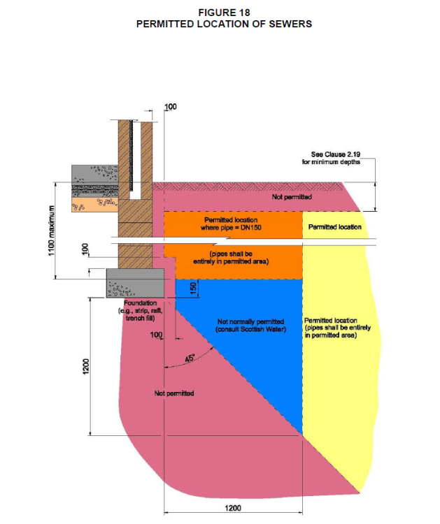
Hi Richard. You're going about this the right way. Yes good info and probably the starting point really to make progress. I have designed a few solutions for build over permission where we have a run of houses with the public sewer running up the back of the houses, very similar to yours... it can be done with a fair wind. In some ways having the old combined system can be a blessing as you only may have to make one connection and maybe blank off other existing ones. However, depending on where you are some water companies are not keen on you adding rainwater flow to the combined system as this exacerbates the problem with stormwater overflows spilling into rivers. At some point they may or may not ask for flow calculations. Leave that for now as it is in itself a lengthy topic. There are loads of folk on BH that know a lot about this, ask if you need to. For all... generally. A private sewer is a drain you do not share.. you own it. A public sewer serves more than one house and generally the water company own that. These public sewer run into main sewers.. often the big one in the road. In this case the drain being build over is a public sewer. There will be branches in the public sewer that connect into your bit of drain from your own house. You generally own (private sewer) the upstream bit from the branch socket. Also, as this is a combined sewer your rainwater pipes will be trapped and then connect into the public sewer. This is relevant later once you get into the detailed design as you often find that the trap and other connections start to obstruct founds etc and you compromise the ability to rod the drains. You may be lucky and find that the rain water down pipe serves both houses and the trap is on your neighbours side. I recently designed something like this in Scotland, similar rules apply in parts of the rest of the UK. This is the Scottish Water compliant method I used to get the build over permission. The line of houses were on a slope and the gardens were terraced. The manholes were away from the site.. I could roughly figure where the drain might be but not how deep as did not know the fall and also folk had been regrading the gardens over time. 1/ @saveasteading, yes I got the plan which indicated the MH covers and invert levels. That got me on the ball park. The main thing to recognise is that the record plans are often far from accurate and ofetn incomplete. 2/ The Client knew that the neighbour had a MH cover in their garden that was not buried under flower borders etc so after asking nicely we were allowed to lift the cover. Good news the invert level was not too deep. The year before I had one where we lifted the cover and could nearly see Australia. After a bit more investigation we abandoned the job as the drain was so deep it needed an expensive structural / gorund solution to deal with that and a couple of other things that just made the project uneconomic. At least we found out early on! Everyone was dissapointed, including me. 3/ Next was to get an approved Scottish Water company to do a CCTV survey. This was one of their (SW) requirements. We put the camera into the neighbours MH and fed it uphill to about 1.5m beyond the far boundary. The equipment they use is pretty good. Now we knew the line of the drain and the depth to about + / - 200mm. We could also see where the branches were connecting in. Importantly we were able to assess the condition of the drain and how good the joints were. Some of the joints were leaking and there was a bit of ground water seapage into the sewer. You could see a couple of little water spouts! Anyway the CCTV guys said.. not bad and the drain looks ok, SW should be happy with that. The CCTV folk do a formal report, a sketch plan with some dimensions. They also send a natty video and at the bottom you can see the calibration so you know where the camera is. The camera gets a bit of a hard time as it's amazing how often folk flush their toilet. This give you confidence to make the next step. 4/ We next hand dug a pit to check the CCTV info. Found the drain and the rainwater pipe trap which was bang up against the boundary retaining wall. Because the drains were at an angle it was clear that we needed to design the founds for this. But at least we knew what was what and could plan for that rather than risking problems during construction. 5/ Next was to design the drainage layout, prepare the drawings and then submit the CCTV survey package and the drawings for SW approval. Part of the approval was conditional on us getting a post construction survey. Screen shotted below is part of the build over approval so you can see what kind of thing the water companies are looking for. Ok that is.. call it the permission side / admin. But what sort of drawings do you need and how to design a build over up the back of of say @Richard Marin's house? My starting point is to go to the Sewers for Scotland guidance. It has a diagram that shows the zones where you can do stuff. You'll see lots of similar diagrams produced by water companies over the UK. Next was to marry this up with the site levels, look at options and get the best drain layout that suited the actual thing we wanted to build, in this case a rear extension. I have attached the two drawings that were submitted along with the CCTV survey to support the application for build over permission. I have edited them a little to remove identifiable info, if I have missed something can folk let me know? All drawings need a title box, sometimes it's good to let folk turn on and off the layers if using pdf. There is a fair bit of useful info on the drawings that lets you see the level of information that results in a good application. Hopefully they give you food for thought and point you towards what you need to know about your project. Please bear in mind though.. there is a bit of my IP in there which I don't mind sharing as I learn loads from BH and enjoy the enthusiasm here. One important thing is that these drawings show part of the foundation design. What they don't show is the structure above and how that fits with drawings you see. For example the drawings take into account the loading from above, building stability, soil pressure bulbs, what impact these will have on the existing house founds and the retaining wall adjacent to the existing house founds. In other words don't just copy the info and hope for the best.. or you will end up in trouble. Just to finish. You may be thinking.. is this overkill from Gus and how much does is that type of application going to cost me? Cost.. not as much as you think... probably the wrong phrase to use if in say Yorkshire. Good planning like this keeps the build cost down and reduces the risk of the unforseen. The dreaded "invoice from the builder for extras".. which they have a habit of submitting when they know they have you over a barrel, risk is reduced. But also you put loads of time, effort, invest your emotions.. and money into something like this and do it right. But what if your neighbour builds out the back, they are gung ho, damage the drains and put your extension at risk.. Oh.. now that post condition survey suddenly comes in handy, especially as it went 1.5 m beyond your boundary. Think of this CCTV survey as buying a bit of insurance. @Richard Marin Hope this gives you a bit of insight and allows you to pick the best bits that suit you and disregard the rest. Keep us posted and all the best with the project. DRG-SW01 Foundation and Drainage Layout A2.pdf DRG-SW02 Rev01 Drainage and Cross Sections A2.pdf
-
Hi @DissyStitch Oh trickle vents.. subject of much discussion. Ok to explore. Yes while you may feel you have agreed at the time and are now feeling boxed in you are afforded quite a lot of protection as a domestic customer. Now the contract you signed can't be unfair under the terms of the consumer protection act no matter what the double glazing company think. The contract you have even if loose is much different from a commercial contract where we expect that each party is experienced and has taken appropriate professional advice.. this type of commercial contract.. there are no friends in the desert here. But for you a court will take into account that you are a domestic and inexperienced Client. "They said that vents are not required if 30% of the windows are replaced at a time. " Now if you have that in writing then that is grist to the mill. Basically it is their responsibilty to check that they have are complying with the building regs and they also have a duty of care to you. The first question to ask is.. you installed the windows and where is the justification for your 30% view, the staged application process and how that sits with you having a correctly ventilated dwelling at the end of the day. Now it seems you have to some extent colluded to circumvent the ethos of the regs.. but they as a professional company should never have suggested you do this in the first place. If you write to them asking for justification and they don't respond then now you have recorded that. Anyway you could just chose to run with it, but you know the risks I think. Or you could get a bit rough with the window folk and start to find other faults with their work and this allows you to put pressure on them.. you skin the cat another way. If I was asked to find faults I would start for example to look at the mastic around the windows for compliance, see if they are they are fitted in such a way that they compromise the insulation or not, then the drip on the cills, is it enough (NHBC like 40mm of a drip), check that the windows are square and that the drainage is working.. by pouring water into the bottom of the window frame and checking it comes out the front somewhere. I would also see if they have mucked about with existing load bearing lintels for example or damaged say roughcast. This is part of the visual inspection side. Next stage is to say.. do we expose what is behind the reveals on the windows and look at the brackets and check they are ok structurally and as per the manufacture's specification. We also check that they have not compromised the fire barriers / cavity insulation if applicable. At no point do we touch the window itself so as not to let the installer off the hook.. lots of photographs. Next stage, the full Monty, would be to look at how the window is actually glazed.. have the glazed units been installed in the frame correctly and packed. Here I would call up someone say like at @craig and say do you know this system, how do we get the beads off to look at the glazing packing and can you send someone that knows how to do it without damaging the window? The objective of the above is to bring the double glazing folk to the table. To do this you need to find the stick to beat them with. The trickle vents.. we go full circle and ask.. did you assess the ventilation before you installed the new windows? How do you justify your approach. Have you made the ventilation worse and compromised the other parts of the house. Never mind your fly stuff about submitting the thing in stages.. you have a duty not to compromise the rest of the house so lets see your figures and evidence.. and we will take it from there.
-
Wrong Sand - is it still ok for bedding mortar?
Gus Potter replied to ChrisE92's topic in Landscaping, Decking & Patios
I think you will be ok. Buy some mortar plasticiser and do a trial mix with the grit at 4 to 5:1. Don't use fairy liquid as an alternative plasticiser. Much will depend on the weather, how fast you can go laying and whether you have a mixer or are hand mixing on a board. Give it a go and see how workable it is. If you find it is not that workable buy some soft builders sand and mix that in to the grit as the soft sand has the fines content. You won't need much soft sand. In some ways you want your bedding to be a bit porous as it is less frost succeptable so don't over do the soft sand content. Any left over then follow @Temp advice. -
Hi Mike. Thanks for posting this, very interesting. Also thanks to all the other folk chipping in, makes great informative reading. I have loads of question and like @saveasteading am enthusiastic about the idea but also cautious. A few of my thougths are: The durability. Yes they have a guarentee but if they do have a 3.0mm thick wall then I assume they are galvanised, if so what kind of steel are they using? One weak spot for me seems to be how they connect the plates to the top of the piles, are they welded and if so how is the protective coating made good after? For me I want to design houses economically that are going to last a lot longer than 50 years for many reasons. I think there may be a lot more lying behind this that you and your SE knows.. but we don't. Anyway for a bit of fun.. and hope this helps crystalise / inform your thoughts. The muck away cost, depth of made ground and what is in the ground. If you have reasonable access for say a JCB with an extra dig arm and some space at the front of the site to stockpile for lifting with a lorry with a grab then that is a way you could get the muck off site. But what is in the muck? Have you had the ground tested and the soil classified. The easy way to go about this is to phone up local muck away folk that know the area and transport costs etc. Ask them what they need and go from there. Sometimes you can have a bit of soil that is contaminated and the rest of the site is ok. If you can get a handle on this, say by testing at different depths and places you can work out how much soil is inert and how much falls into say the non hazardous category. The next stage up classification wise and the muck away cost increases a lot. What muckaway contractors can do if you only have some soil that is not inert is to mix it a bit with the inert stuff so that it can all be classified as inert.. and that brings down the cost... can be a lot... like lots! Do you know why the test pile was only inerted to 1.5m ? Maybe your made ground is not that deep? I'm curious how the design works holistically. You have neighbours next door? .. what if they build close to the boundary, plant trees or the boundary walls need repair. Will that cause you grief later on if they destabalise your piles. I wonder if this is worth looking at? My gut feeling is to go for the simple stupid that local contractors can deal with and avoid big costly errors and all the stress that goes with that. Around the perimeter dig hit and miss pits say 600 mm wide with a 900mm long base at the level of the good ground. These would be spaced at say 2 - 3.0m apart. Think of this a bit like partial underpinning a building. Doing it this way means you are less likely to cause problems with the boundary walls etc. This gives you a series of pits around the perimeter and the boundary walls etc remain stable. Now maybe dig two more lines of pits running front to rear parallel with the side walls of the site. That gives you a grid pattern of pits and splits your effective structural floor slab span into about 2.4 m.. the benefit of the grid is you can span in two directions which introduces economy. Think of it like a carpark floor slab with columns in both directions. You can finnesse this later to deal with point loads. Also the made ground may vary in thickness, A JCB with extra dig (3.5m) will get you down to 2.2 - 2.4m, the extra dig gives the reach to get into the corners of the site and allows the driver a bit more room to manoevre. You fill the pits with concrete to create piers in the ground. They are just concrete piers and not reinforced with rebar. If the ground does not contain sulphates or has not been used as say a scrap yard where folk have been tipping out acid for years then the concrete will last...acid is not good for concrete as are suplhate rich soils, we need to classify the ground as non aggressive to concrete. If so then I would first look at using a GEN2 concrete. The GEN2 has a compressive strength of 15 N/mm^2 so a fairly week concrete and reasonably cheep. Get a price for that to gain early confidence. You can work out the volumes for muck away. @saveasteading gives the best advice here. Ok.. when you look at this idea and the practical side.. how do you do that? Well it's all about sequencing of the works.. keep the machine working, the concrete arriving and the muck getting carted away. What you don't do is did all the pits, then try to get the muck away and the concrete later, by that time for example a lot of the pit sides may have collpased.. and then you site will look like it has been cluster bombed. Start at the back, dig enough for say a 6 or 8 cube concrete waggon, fill the pits and carry on or have the weekend off. Now you don't have to be that accurate! The site will get churned up a bit, levels will get lost, try and keep the alignment though. The secret is to leave the concrete in the pits high. The next morning the machine just scrapes off the green concrete. As an aside the general rule for pile placement... we usually design for the pile being 75mm away from where it should be as shown on the drawing.. we are not talking precision here.. it's ground engineering. Once you have completed the installation of the piers you are out the ground and on your way. Assuming you have a two storey house my starting point would be to aim for a 180 - 200 mm structural slab and then see if I can get that down to the 180mm thick side, if so is there any benefit. Maybe better to have a 200 thick slab on a self build and not have to thicken the slab edges.. much easier to do on site, less opportunity for construction errors.. can we do it flat all the way. The made ground. Well assume we have scraped off the green concrete tops of the piers to say 0.0mm / - 50mm. I would want to guard against the fill (made ground) swelling up and lifting the slab. Say there is a bit of swell potential. Lets put a bit of 50mm clayboard in, that once wet falls to bits and lets the ground swell. On a 9.0m span we need some watering holes to collapse the board later, easily dealt with. Main thing is not to leave the piers high as that cuase punching through the structural slab. Next stage is to design the slab. Now we need to keep an eye on the rebar area vs the slab thickness as it is a structural slab.. story for another day. In essence a slab that is too thick can eat rebar.. so thickness is not always good. Now we have a structural slab, reinforced locally to deal with point loads.. but really simple and easy to construct. You now have a simple platform to put the rest of the building on top. Simplicity = Savings. Put a structure on top with the perimeter built off the slab, use say marmox blocks to make the thermal breaks round the external walls and standard details. There are loads of folk on BH that know this approach like the back of their hand, have been there and worn the tea shirt.. and know it works, some can even prove it. It may be worth revisiting your design concept, speak to your SE now you have got a bit of feedback from BH. Your SE should be fine with you and recognise that they have a Client that is going through a learning curve. They may ask for a bit more but as folk are hinting on BH there may be different ways of doing this that will easily offset any extra your SE may ask for. Hope this helps and have fun with your project, it's something very few folk get to do.
-
Yes good point.. like that.
-
There was a fair bit of load. Behind that wall is a big open plan space running gable to gable, there is a fair chunk of roof also. The first floor joists frame into the inner leaf, thus floor load also on the strongboys. The strong boys were supporting both inner, outer skins, the first floor and part of the roof. I had designed and specified props on the inside, steel needled with lacing and diagonal bracing between the props. The temporary works were also designed to resist a bit of temporary wind load on the gables. The props were resting on the edges of the concrete slabs, under the slabs was clay.. like soft butter, no appreciable strength at all. None of the props were in tolerance plumb wise as per manufacture's recommendations. If that was not bad enough they had then gone ahead and knocked out other walls on the inside, the folk were still living in the house. The thing is that to do it right would have cost another say £700.00 quid and an extra day and a bit time wise for a couple of guys. All they had to do was follow my drawing. The lacing and bracing is just done with standard scaffold tubes and couplings.
-
@ADLIan sums it up. You may just get away with this but not ideal. Your Architect is rightly cautious and probably nervious about approving this. To solve the problem you may want to pay your Architect a bit more and ask them if they will arrange to get this analysed for the dew point. If it comes back clear cut that the dew point is above the VCL on the top side of the boarding then you are on the right track. but you need to make sure the VCL is the right type and has been installed correctly for your own benefit. Next you need to check that you are still achieving the U values for the roof as the 25mm below is subject to the repeating bridge of the joists. The repeating bridges will have reduced the thermal performance C.f having the uninterrupted insulation on the top side. Lucky you.. that suggests you have a bit of spare capacity in the insulation or BC have missed the repeating bridge effect and the shift in the dew point. For you own piece of mind get the dew point checked. If the roof starts getting wet that will cause big problems later on, a bit extra heat loss?.. well use common sense and beef up the insulation elsewhere for you own interests. When we get problems like this we take a compensatory approach.. add insulation in easy places to counteract the builder cock ups to some extent. If it all goes horribly wrong.. probably not.. then before you rip the roof off consider adding more insulation and a new membrane on top of the existing. Often you find that if an extension you need to get the roof flashing in under the upper floor windows. Or you could take the ceiling down, take the 25mm insulation out and compensate else where insulation wise. There are often plenty ways round this so don't worry too much about this for now. Talk to your Architect, make sure you understand the potential problems, make an informed decision.. then you will feel much happier. On this ratio of insulation above and below the VCL you may find your are ok. Mind you what on earth was your builder thinking about when they deviated from the Architect's spec?
-
Here is some food for thought. Concrete blocks tend to shrink mostly. The stronger the block the more shrinkage you get. ie a 7.0 N block will shrink less than a 10.0N block as the 10N block tends to have a higher cement content. Concrete blocks can swell, mainly to do with thermal expansion on a very hot day, the outside face expands more than the inside. During prolonged heat the whole wall will expand. But the thermal expansion is relatively small in comparison to the concrete shrinkage. Clay bricks are a bit more tempremental. Generally they also expand as the minerals in the clay and chemicals resulting form the firing process react with the air for a good number of years. They also shrink / swell as the moisture content changes. Think of a clay brick more as living material. It can swell and shrink where as a concrete block tends to mostly shrink. In summary when designing I would for standard builds look at putting a movement joint every 6.0 m maximum in a block wall and 9.0 -12.0m in a brick wall depending on the brick selected and then review. But it gets a bit more complicated than that. You also need to know what other walls are framing into the wall; corners (internal and external), window / door lintel positions. All these features introduce stiff and weak points. This variation encourages the movement to take place in an uneven way and that encourages cracking. To do a good job you do want to have a look at the founds, even if to say, yeh I had a look and know I have checked the following. You may have a set of cross wall strip founds but heavily loaded external founds.. both will move a little differently. Also you may have a big set of bifolds with large point loads, the found will tend to settle a bit more or less here depending on how it is designed. The other thing we need to consider is the strength of the mortar as generally this has a cement content. Too strong and it locks the blocks together and shrinks and swells in its own right. @Mike and @nod can see where you are coming from here. Often separating the found from the superstructure is a plastic DPC which should allow the wall above to slip about on the underbuilding thus relieving the stress. But how much stress relief that develops is a bit of a guess. Ideally if the bedding was perfectly flat this may work.. but in real life on site this is hard to achieve in the heat of battle. In summary for blockwork under the usual conditions that apply on a building site I would not hang my hat on a block wall longer than 6.0m without some kind of joint. There are two main reasons for this. I need to be sure that the wall won't crack for safety reasons.. and also if it does crack and becomes unsightly I'm going to get in the neck anyway. Now.. the fun part. many years ago, some 25 plus (did not know then what I know now) when I did a self build as a young lad I wanted no joints in I think a 9.0m block wall. I was just starting out and had employed an old school SE. He suggested that I use concrete block but in a lime mortar. I did not know enough about lime mortar back then so bottled out and just put in a joint. But I wonder.. would I design something like this now? In theory I would have a look at it. Maybe start with an NHL 3.5.. and if the exposure is benign maybe just have a look at NHL 2.0.. oooh! Now the lime mortar moves and lets (in theory) each block shrink as an individual unit... and that will let you build a longer wall beteen joints. My concern here would be the render and the practical side of this. What kind are we going to use? We are talking doing big panels in one hit. to make a good job.. a change in the weather, someone twisting their ankle on site, getting a dose of the runs and you could end up with an expensive and frustating out come. If you could get it work structurally, in the round I would want to balance the risk of cracking, a rough uneven finish with using standard joints. My gut feeling is to go for the tried and tested method of joints at 6.0m or less in blockwork if you don't fancy taking too much of a risk. Would be interested to know if anyone has used concrete blocks with lime, if so how did you get on?
-
I'll come at this from the practical installation / designer side. Start with the beam and block flooring. See manufacture's literature.. the beams tend to be bowed upwards as they are pre stressed concrete. That is your starting datum. The thin point is in the middle. beam and block floors are not flat! Next is the PIR. Often you find the PIR sheets have a bit of a bow.. they should be flatish but you get sheets that are definitly not when they turn up on site, but you are buying a small quantity as a one off.. so you lack clout to some extent.. you have two possible obvious choices.. have a barny with the PIR supplier or live with what you have... a barny will cost time on site, and you have to know your stuff about tolerances to be in a position to reject material. You need a bit of weight to bend the sheets back flat. Pipe congestion. There is software that you can use to lay out your UF pipes.. looks great.. but all the pipes coalesce as you near the boiler / manifold.. that is the bit where the softare falls down. Also you may have to get around structural components, things the SE / Architect / you are not keen on you altering. For me I would go for a 90mm to 100 mm screed. The cost lies not so much in the thickness but good preparation. Setting plenty level datums and so on and making sure you can get back in to polish the odd rough spot. Now you want an engineered wood floor. Have you looked at the warranty on this? The wood floor folk make it REALLY difficult to stick within the temparature range.. and that includes areas where there are conjested pipes. If you want to stick the rules re not eceeding surface temprature.. hard to do at times.. that little bit of congestion can drive the design if you want to comply with the flooring warranty. This leads to a thicker slab / screed to try and comply with the flooring warranty. Next is do you glue the flooring to the screed or float it? I've tried various options over the years tackling UF.. I'm kind of.. if you don't like my opinions.. I have others. At the moment I'm experimenting on my own house. I have floated an engineered floor on a 2.0mm foam layer on a structural 100 mm thick concrete slab with A142 mesh and some movement joints on PIR. Yes I know it is an insulating layer.. but I made the insulation under the floor a bit thicker.. so far been working great for the last three years. The big thing here is that the UF tends to go off in the summer. Funnily that is when the moisture content in the floor rises so swelling occurs in the timber flooring, sounds odd that the moisture content in a timber floor rises in the summer with UF! I decided to float as opposed to glue as I have one floor that is big but about half is over a timber suspended floor , the other over a slab / PIR. At the back of my mind is this. If something goes wrong if floated more easily fixed. Also one part is the kitchen area. If I get a flood maybe easier to fix than if fully glued. But another big thing for me is how I want to live. My wife (a buddingdesigner also) likes rugs (our spaces for example change from season to season) and the things that make a home a home.. for both of us. We have eye to the future.. we want to be able to sell the house to someone who may want to live differently from us. If you don't want a sterile environment .. be able to put down rugs, bean bags, large sofas that insulate the floor that act as an insulator then I have found that embedding the UF pipes in about 90-100 mm of concrete material provides room for pipe congestion, accounts for tolerances in the substrate below and distributes the heat more than a thinner screed / slab. We have a few rugs that insulate the floor but eventually the heat gets out.. yes I know not perfect.. but we have a house that is designed to be flexible and easily adapted... depending on our mood. My advise is .. go for a thicker screed as it will mitigate hot spots and make on site construction much easier. The game changes a lot if we are doing this at first floor level for example as we are adding weight to a structural floor spanning between say walls C.f a ground bearing slab arrangement. In terms of overall cost I think that a thicker screed distributes the heat more eavenly but the big thing is that it cuts all the trades folk /PIR / flooring supplier and even the SE a bit more slack and that will drive the cost down much more than say reducing the screed thickness. Ask builders to work to tighter tolerances costs a lot more than making say a screed a bit thicker for ground bearing UF applications. Compare the extra cost say between making the screed 30mm thicker.. 70 - up to100 mm . Now take a tradepersons rate ( a good one) at £250 - 300 per day. Work out how much extra time it will take the trades folk to work within a 70mm screed and for the flooring to work. Then compare with the extra cost 30mm of concrete. I think once you look at this holistically and talk to your builder you may find that the simple stupid thicker screed is the way to go. In summary if you are thinking about this sort of stuff and it's new to you then always think.. yes I can see that folk say on the internet that they can supply a thinner / stronger product.. but look at the knock on effect in terms of the other trades that have to work around that and how used to it they are. You local builder can be great value if you play to their strengths. Lastly if this is your forever home.. always think about.. what if there is water ingress, what if say in ten years time we want to lay tiles.. in the round you may regret not just putting in a thicker screed.. the extra concrete is not that much.. the cost lies in the preparation, the laying squad coming to site, the plumber having to get all the pipes so they have cover and so on. It's like baking some cakes (so I'm told).. sometimes heating the oven cost more than the ingredients.
-
Foundation near tree line - raft? Systems available?
Gus Potter replied to Pabbles's topic in Foundations
I would spend a bit of money on a ground report and identification of the trees and vegitation. That really is your starting point for me. Next I would look at the weight of the super structure.. how does it work and does what you have work best for the ground conditions in the round, budget wise? Would a portal frame work instead? The slab thickness you mention.. 250mm.. that is a chunky slab..that is getting close to/ is a very heavy industrial slab.. It looks too thick. You mention a twin post car lift. It's not acutually a big load.. have designed plenty MOT stations with double lifts.. worst case needs some extra rebar or local thickening. If you use a 250mm slab as a structural member then you will need a lot of rebar to comply with the codes. The material cost will escalate, as will the construction cost.. the aim here is to keep it as simple as you can so your guy can build it with little complexity.. and have to worry less about concrete curing and so on. If you want a bit more out of BH what can you tell us about the ground and type of trees? You do have a bit of a challenge on your hands.. but if you can let us know a bit more about you'll get some good pointers on BH about how to tackle this engineering and cost wise. Looking ahead. How do you want to finish the floor? Are you going to paint it and for the garden office.. assume you are going to insulate? Two distinctly different designs are require if so. -
Appreciate your frustration @Dave Jones Thing is that when the timber was put through the grading machine it may have been ok. Fabricated trusses tend to have their own special grade of timber TR26. Remember that when the timber is tested we work on probablities and normal distribution curves to determine strengths. Here what you have is some splitting timber that could be outside the 95% percentile. But it has been spotted before it got built in.. that is good that you have spotted this as in some ways it shows the system works, awareness from site operatives.. if it looks wrong it probably is. The timber could have dried out after grading and fabrication.. wood is a "living material" and is full of surprises. We design for the odd concrete cube test not being strong enough and say for the odd truss being crap as we know that really one off bad one.. say like you have will hopefully get spotted. If we designed on the basis of everything being perfect houses would cost an awful lot more to build. Options that spring to mind. 1/ Send the photos to the truss folk and say you are concerened about the splitting. Ask them to confirm that the material is still compliant with say TR26 timber / their design and that this may be outside the normal expected strength / material property distibution. 2/ Ask them if one or two can be remediated.. at their expense or how quickly you can get new ones and the old ones taken away also at their expense. Express you preferance. 3/ Say you expect an immediate response and warn you will follow up with more in depth enquiry if not the case.. starting with how this got through their CE marking process, sent to site and that they are now not responding to reasonable enquiry about a safety concern. The key is to state the facts, send photographs and say this is a structural safety issue.. and that it is costing you money due to delay as you can't progress the works due to a safety concern. I think you may find that you have new trusses in two to five days at no cost to yourself. The reason is that when faced with a few photos and technical observation the manufacturer can fast track stuff to head of bigger problems and claims at the pass. The above is the way you start to lay the groundwork for a legal claim if they don't play the game... but that is very remote.
-
Opinions on best way to drop a ceiling
Gus Potter replied to Thorfun's topic in General Construction Issues
In terms of structural safety, yes. But we all have a civic responsibility and structural safety is paramount.. But let me also appeal to all on these grounds... Why not make sure that you have built something that will really last, maybe a lot longer than it's design life, be proud of it, leave a legacy? Yes I know it's about the money.. but you have put so much work into this.. In terms of your wallet. What happens when you apply for you completion certificate. Who signs to say that the building has been constructed as per the approved plans? If it becomes apparent that you have added undeclared load what then? .. that can develop into a big problem, habitation certificates, lenders not playing the game etc. If it was me signing off your house I would check you are not pulling the wool over my eyes at not just my expense / risk but for the sake of all the folk who may own the house after you. But the other side of the coin is that I would try my best to get it to work for you and prove it and.. that may take a bit of innovation and lateral thinking. I would play this off a straight bat, rest easy and be proud of what you have built without any worries. Cost for a design review. If you have all the calcs and drawings that is a good start. But there is probably manufacture's data missing. So a bit of due dillegance required here, phoning about for the SE and talking to you to tease out what you have really built. Say 3 days work with full disclosure from you and payment on the nail. It carries liability so say £400 a day = 1200. depending on who you get there may be vat on top of that. That will be on the ball park to get you the checks you need. What you won't get for that is any kind of warranty that you can then pass onto a third party. There will be caveats.. for example if the checks reveal that there is a flaw in the original design then it's a different scope of works. Also, if you can't access the joist data in particular lines become blurred. Things like this happen if companies have gone bust. There are ways of tackling this but it takes more time. If you go to a larger SE outfit then a graduate rate is say £85.00 per hour. -
Opinions on best way to drop a ceiling
Gus Potter replied to Thorfun's topic in General Construction Issues
Had a very quick spin through the parts of the calcs you have posted. The output is not that clear and to really consider this we need to be able to see all the data that lies behind the the output. In other words to check this we need a lot more transparency and need more info. On the face of it though in terms of the joists themselves it looks like they have spare capacity to take a bit of extra load in terms of strength. But we also need to consider deflection. Looking at the output you may get this to work ok and still be within the limits set by the original designer. It looks like you have about 20% to spare deflection wise and it is deflection that appears to be governing the joist design. There are some vibration checks.. good to see. Adding a bit more dead load should not be a material factor on this relatively short span. However to do this responsibly we need to then trace the extra load all the way down to mother earth and look at how this extra load may impact on the other parts of the structure. For example.. we need to check the joist end supports.. are there lintels below, if so what is their capacity?.. does this extra load cause more bending effects in say the masonry below / above due to the nature of the joist end supports acting possibly at the face of the walls rather than dead centre over the wall. Often all works out ok.. but adding or in fact removing loads from a structure must always be checked. Sometimes if you remove a permenant load it can cause problems.. good example is a basement in water. Remove the ballast and the thing can suddenly float upwards! Another is where you may be relying on weight to stop a roof lifting off. Swap dense masonry blocks for lightweight aerated ones.. often done to reduce heat loss if you can't get the u value calcs to work.. if there is not good communication between the design team this is the sort of thing that gets missed... very easily done! In the round though based on the summary output you have posted it looks like you can add a bit of extra load subject to detailed checking. Advise you proceed with caution. If the joist manufacturer is no longer trading then there are some other avenues / ways a round this with a fair wind but story for another day. -
Feel for you. Much will depend on just what stage of the work you are at. Seems like the beam B1 is in place but no extension roof? I had a quick look at the extract of the calculations. I can't see page 7 but the loading used to design the beam looks about the right magnitude holding up a bungalow roof and the load from the flat extension roof. The mention of a second storey is probably just the SE maybe just calling the bungalow roof the second storey? The beam is checked for at least three criteria. Strength checks.. moment capacity Mc 429.9 kNm, buckling strength Mb 145.9 kNm both of which are greater than the design moment applied to the beam = 121.5 kNm Deflection is also checked against a limit of beam span / 360 = 19.6mm, calculated deflection is 10.883mm I get 10.9mm .. close enough. However B1 has plates welded to the top and bottom flange which stiffens the beam quite a lot. Thus you would expect that the beam deflection would be less still and if it is less still why are they (the plates) there? One reason may be that the SE has decoupled the calculations and assumed that as the loads are not over the.. call it centre of gravity of the beam and we are only seeing part of the calculations. This eccentricity causes the beam to twist more and the SE may have designed the plates to resist this extra twisting and left the remainder of the beam to carry the other forces. The main thing here is that I am not casting doubt on the SE's calculations but would ask out of curiosity if this is the reason for the plates. Also the plates are shown as the same width as the beam flange, nominally 173.2mm. To get the plate flush means cutting a long standard flat bar down lengthways.. more expensive and also if the plate is flush your standard fillet welds are not appropriate. You need to use partial penetration welds or similar which are more expensive. Normally I would use a standard 200mm wide plate which give loads of room for the standard fillet weld, especially as we know that not all beams / plates are truly straight. Again I would ask.. why was it done this way and are there other underlying reasons for this design approach that are not immediatly apparent. Now this is really a mute point as the steel is paid for and B1 is in place.. other than it will let your SE know that you are now better informed. It is what it is. It's a great pity that neither the Architect or SE alerted you to this low height much earlier. But what options might be available to raise the soffit of the beam. Well it could maybe go up quite a lot until the bottom is almost level or just above the ceiling of the extension. Here we would do a bit of joinery work to brace the existing roof trusses as we would be disrupting the joint between the existing roof ceiling joist and the rafter. Turning to demolishing and rebuilding the supporting walls. Ideally we want to avoid this as these walls are probably offering sideways (lateral) support to other walls so when rebuilding you have the problem of re tying your new masonry into the old. In other words you risk making matters worse. Under the padstones the inside edge of the wall forming the sides of the opening can flap about and that will be bothering your SE. If you can live with it can you narrow the opening under B1 by say 100mm each side. What you could look at is either introducing some good solid timber posts fixed to the wall or maybe a couple of light steel channel sections, timber is cheeper. Now we have stopped the supporting wall from flapping about and they will carry a lot more load... which means they may not have to be demolished after all. If the builder can give the SE the hand mixed recipe they used for the padstones and the concrete looks well compacted it will probably be the same strength as the existing brick and thus they could just stay in place and put another cut down lintel over the top once you lift the beam. That could be one solution worth exploring. I would aim to keep on good terms with the SE , builder etc.. but start asking a few informed questions. It may be that your SE comes up with some good / other solutions.. free of charge in the interests of good will. Hope this helps and things pan out ok for you.
-
Hat off to you for giving Enerphit a go. Here is a question. Is it important to you that you reduce your carbon foot print and overall footprint on this earth during your life span? It's a serious question as you clearly know your ins and outs if you have been exploring Enerphit. For me.. a bit of a philstine I have an ex council house that I am insulating as much as I can, experimenting with eco stuff.. but recognise that if I demolished it then the real carbon footprint would be prohibitive unless I put a life cycle of 200 years on the house at least. Stuff like planning fees.. I can get a lot of insulation for that! Keep us posted on your thoughts.
-
Glad you have found BH, you'll learn loads here (I do), get the benefit of all sorts of different views and if you stick at it.. will allow you to make informed decisons that suits you best and save money along the way @greenqueen"In your opinion what foundation type is best for sandstone rock and sandy soil" The design process goes a bit like this. Rock / sand .. lets start from experience by looking at strip founds and then work up in levels of complexity = cost. Sandstone = good start. Now lets look at the type of sand, where the water table is and where it may be in the future, how thick the sand layer is and if the site is sloping. Breaking this down. The type of sand is important. Are all the grains of sand roughly the same size (poorly graded) if so they can act a bit like a pile of marbles so the bearing capacity is less or.. is the sand well graded where there are small particles of sand and big ones that all interact, have a larger area of surface contact and thus have a greater bearing capacity. When the sand particles are submersed in water (where the water table is and where it may be in the future) it reduces the effective density of each particle of sand by about half (Archimedes) thus as the bearing capacity of the sand relies mostly on intergranular friction we need to know about the water table. We also need to know about the water table is as when we dig a hole it may flood. You can dewater but one big risk is that you suck out the fine particles and make things worse Also you may have so much water that you can't easily pour concrete. If you have a high and mobile water table this may lead you to look at the raft option early on as you keep it out the water table. Of course if the water table is really high then you need to remember that EPS etc floats! If the site is sloping then ideally we want to found the building on the same soil strata, not half on the rock and half on the sand as this leads to differential settlement which can "break the back" of a house. To conclude this part. I think you need to get a handle on the ground and that will help you focus on the viable options that suit you. Post your ground investigation results if you wish for some feedback. @greenqueen " If we are going to build with a combi oak and sips frame, how does/does this affect the foundation type? " As other have said .. sips is structural @Alan Ambrose so why do two load bearing structures? I think oak frames are brilliant. You mention that you may not want to use them everywhere. But if it was me I would want to have them on full show, no point in hiding any part of them. Yes they do move about a bit when seasoning and later during summer and winter. Funnily they tend to shrink in the winter as we put the heating on and can lower the humidity levels.. a bit counter intuitive? But in reality the movement is not that much different from a timber frame house, probably less so. In summary I would price on standard stuff: strip founds, look at suspended floors or a simple 100- 125mm thick ground bearing insulated slab then add in your extras to mitigate thermal bridging ect to bring the house up to the thermal performance you are seeking. Go for the simple stupid first that local builders can handle.. you'll get more sensible quotes this way. That gives you a benchmark.. then it lets you test each of the bells and whistles options. To try and price this up as a novice I would start on say a standard masonry cavity wall construction or a timber frame for the whole house. Then add in the oak frame as an extra over. Sounds odd but depending on the type of oak frame you go for; acting as a true arch or more portalised (which puts horizontal thrust into the founds of the ground floor or floor slab if a raft) then the hidden extras ( foundation detailng and mitigating cold bridging etc) will be covered by adopting the extra over approach. Later you can start to shave of cost by good design and detailing. Have a look at these.. great idea which works. Turning now to some technical aspects of raft foundations and EPS. This is not "new technology" we have been designing insulated rafts for ages. In the UK they crop up a lot on cold stores and in the USA.. well there is not a lot they don't know about this, and they have to also have deal with permafrost in the northern regions. Be glad we live where we do in the UK! @IanR and @saveasteading You are both correct.. to be difficult I'll add my own interpretation.. all in the best taste.. but I'm going to try and simplify / expand for BH folk.. but may make matters worse.. ! There are many different types of rafts and @George can probably add to my list and chip in. I'll give this a go describing the common types, there are many and they all work in a different ways. 1/ A true raft. This is say a 250 - 350mm thick flat slab that is wrapped in EPS with a two / three story domestic building on top, point loads or intermediate load bearing walls from the second storey and roof load coming down in the middle. By making the slab this thick we reduce the density of rebar which lowers the cost as rebar costs more than increasing the thickness of the concrete. Also by making the slab thick we reduce the punching shear stress that comes from the point loads say from columns to create a big open plan space on the ground floor. In summary you would lay the EPS, turn it up the sides, lay in some rebar and pour the concrete. If doing a basement you probably need starter bars and some stuff to sort out the corners and stop the water coming in. Main thing is that the thick slab reduces the rebar congestion which suits local builders.. keep it simple stupid. An important part is also think about slab shrinkage.. story for another day / later. BH folk.. don't get caught out by trying for the thinnest slab you can as the rebar cost etc can go up drastically and you invite other problems. 2/ A semi flexible raft.. still a flat slab as above. You see this cropping up on BH where the EPS extends beyond the inner load bearing leaf to say the outer wall. Now if you assume the load bearing wall is the inner leaf and the load from that spreads out at 45 degrees the EPS contributes a lot more to supporting the big structural load from the inner leaf. But you often find that the EPS can get over the line. Two main reasons are this: When you look up the EPS spec it gives you a compressive strength of say 200- 300 kPa at 10% compression just say for the sake of arguement. That means that the EPS needs to sink by 20- 30mm before you get your 200- 300 kPa resistance. Now 20- 30mm movement is not going to be acceptable, especially when the ground under may also be sinking. What we do is to say let's limit the amount of load that the EPS can take. I'm not going to tell you this range of values as this is commercially sensitive. If you search about other designers they are not going to give away these values until you cough up a design fee, also you need to know about the ground and the chosen / proposed insulation. To design the semi flexible raft we work out what the EPS can carry and then use the concrete slab to carry the rest of the load. This extra load gets shed back into the slab which acts roughly as a cantilever. But for that to happen we need to design the slab to act like a big reinforced concrete slab. But if you turn the slab into a reinforced concrete slab you have to comply with the design codes that relate to that... and that is very difficult if not inpracticable on a 100 mm thick slab. It can sometimes work on paper until you need detail the rebar anchorage and deal with rebar congestion etc. 3/ The edge thickened raft. Here we have a concrete slab that is attached to what looks like a strip foundation. As above the same principles apply.. the strip found can only carry so much load so we shed the load back into the slab and often reinforce that as the top of the slab is in tension. The edge thickening is often used where we may have point loads from columns. The edge thickening acts as a concrete beam which spreads the load over a longer distance around the slab edge then the remiander back up into the slab. I have to give up here on the various descriptions and way of doing all of this. Suffice to say you there are often loads of different options.. But to add to the complexity we need to consider how big your slab is and how much it will shrink and crack and where can we put movement joints?. When you edge thicken a slab it basically gets anchored at the edges. As the concrete cures it shrinks. A true flat sab can slide a bit but an edge thickened slab is bound into the ground at the edges and thus we often need more steel to resist the shrinkage cracking. Well to finish. Probably the ground conditions are the thing to get your head around, it can be a lot of fun researching your local area, talking to the neighbours, did they build an extension what happened? That basic stuff can save you thousands! And when you move in you already know your neighbours.. that is a good start?
-
Not heard of that term before, ta. Every day is a school day.
-
Crack in wall and sagging bedroom floor
Gus Potter replied to mattsm's topic in General Structural Issues
That is a really good spot! Hat off to you. Has got me thinking.. The Bresummer is under the window cills above and close to the vulnerable flashings over the bay window. Also it's brick, not rendered so maybe some water penetration from a bit of both. I'm thinking.. have the ends of the Bressumer rotted a bit (assume timber) and dropped. If the floor is resting on the Bressumer then it will have dropped a bit too. Check the floor for level and look at the ceilings below. But there may be a 5" iron beam holding up the outer face of the brickwork over the bay window. If the timber Bressumer is ok then has the iron beam rusted at the supports, expanded at the supports and actually lifted the masonry? Over time an iron beam like this can easily lift the masonry by 5 - 10 mm. There may be an iron beam both on the inside and outside, the outer one has rusted more so lifted. The nature of the crack in the wall is interesting. To make headway on a diagnosis you need to examine it really closely as it will yield clues. Some obvious things are to measure how wide it is and it does taper. Next is how much it has displaced sideways. There seems to be a little sideways displacement and a taper. Next is to see how the windows open and shut, check for verticality and examine the paint on the windows. Also try and age the paint on the walls. Does the paint go into the crack.. helps you date things. Ask.. has anyone been messing with the ground floor bay window and were there any massive trees growing in the front garden, problems with the drains for example! You have to look at loads of stuff if only to rule things out.. like have the water board just put a main sewer in the road or is there not HGV traffic (vibration) where there was not before. You also examine the whole building to see if there are any other signs of distress. Going back to the crack. You see it is wider near the left window when viewed from the inside. That requires more info to get to the bottom of the issue. In terms of buying the place apply common sense, look at the whole building and speak to the neighbours for example. Should you buy it? Can't say just yet but so long as the rest of the house is ok, the roof not sagging and other cracking not apparent then if you put in a bit more work you should be able to get a handle on what it may cost to put this bit right.


