Gus Potter
-
Posts
2155 -
Joined
-
Last visited
-
Days Won
26
Everything posted by Gus Potter
-
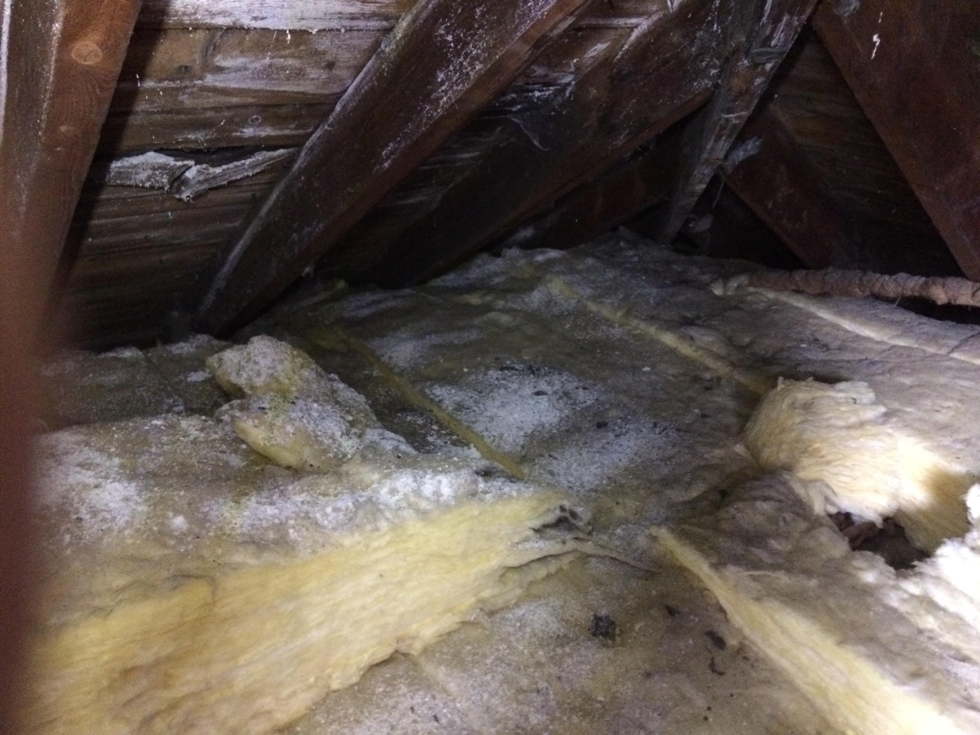
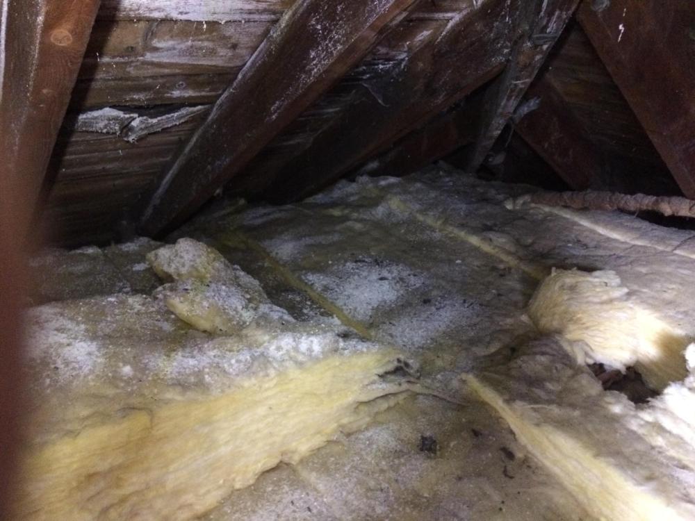
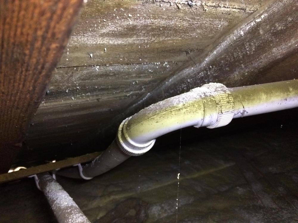
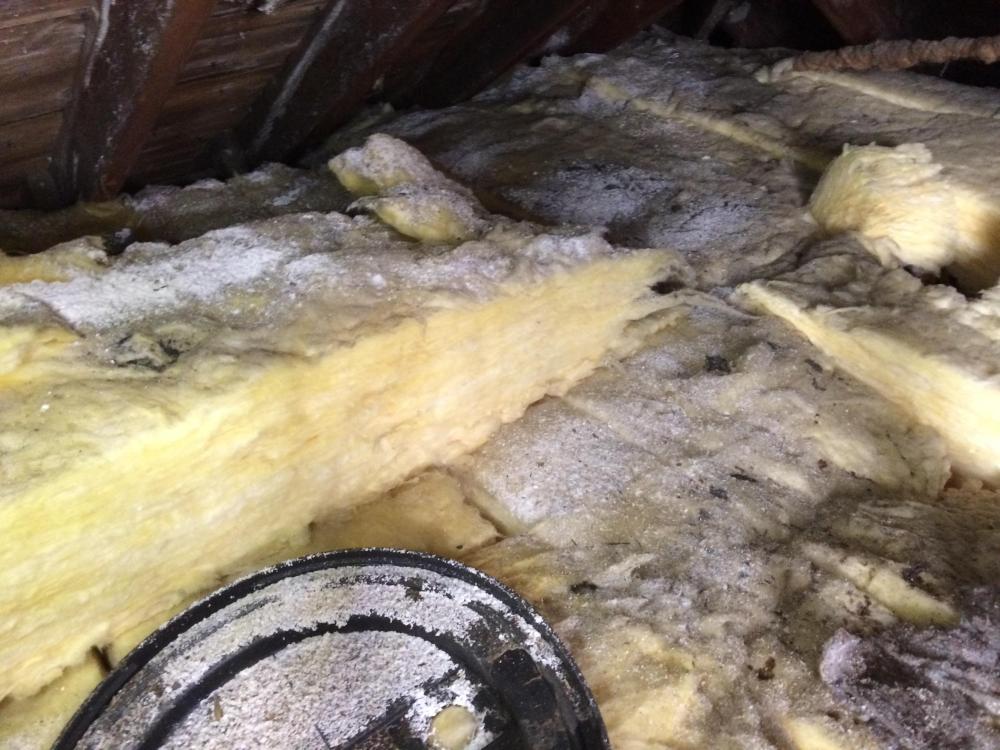
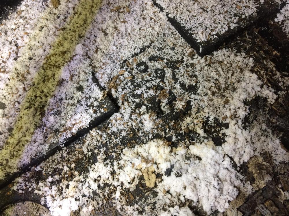
Has anyone got any ideas on this? I have a project; two story semi detached house built circa 1935 with a sandstone exterior skin , probably brick inner skin, no cavity thus it has solid walls externally, internally a set of brick load bearing spine walls. Roof is traditional cut timber with sarking boards. The non load bearing walls on the first floor are lath and plaster on timber studs. What I'm doing is demolishing a load bearing internal wall on the first floor which holds up the attic floor joists thus I need to put in a beam and some other structural support. To intall the beam requires disruption to the first floor ceiling which is attached to the attic joists. I know this about the building. 1 The Client has owned it for say two years. 2/ The roof may have been reslated/ repaired but this was a good time ago, maybe 30 years, possibly longer. 3/ The attic has been lined out but not a habitable space and accessed via drop down ladder. 4/ The roof was insulated with glass wool by British gas.. I can see their warning sign not to walk on the glass wool. I think British Gas stopped insulating lofts some 30 + years ago.. maybe wrong.. does anyone know? 5/ I know that old under slating roofing felts can contain asbestos and they were still used well into the 1980's. 6/ In the last couple of years the roof has suffered from significant leaks and the new owner, my Client has to get folk in to fix what they descibe as a couple of "floods" from roof leaks. 7/ There is no record in the title deeds of the roof having been sprayed for wood worm etc, but that does not mean to say it has not been in the past. 8/ The building has no cavities thus cavity wall insulation can be ruled out. As part of my survey and design I go into the attic and open a small door which lets me see into the roof void.. I observe the following. The above show a white residue on the underside of the sarking and on top of the glass wool. The above shows same residue build up on top of what looks like an old tank overflow pipe. The above shows more residue on the same glass wool but there was also a plastic lid lying on top of the glass wool that has residue in it. The above is closer view of the residue on the plastic lid. Usually I put big warning notes on my drawings if I suspect asbestos may be present, the age of the this house.. well it will probably be lurking somewhere. What I also noticed was that there was a small gap between the sarking boards, could not get good photo without disturbing the residue so stayed well clear. But I could see that through the gap there was some kind of sooty black fiberous material, don't know what it was but it didn't look like old bituminous felt... maybe it was just local.. I don't know. In cases like this I always recommend that an Asbestos specialist survey is carried out.. but I'm naturally curious and want to learn / expand my knowledge. The thing is the residue is quite a heavy build up, so maybe not asbestos... anyway Asbestos is not water soluble My thoughts so far on what it could be are: A/ Is it salts washing off the underside of the roof slates, yes sometimes you do get salts on the slates.. but never seen it this bad. But for this to happen the roofing felt would need to be seriously degraded? B/ The residue on top of the plastic lid means that the residue can't have come from the glass wool? C/ If the roof timbers have had a good soaking has the water washed out possible wood work spray. D/ Has loft space been sprayed and what I'm seeing is over residue from the overspray.. they must have gone to town with the chemicals? The thoughts of BH folk would be much appreciated.
-
It should be fine. I thought you were taking about something 2 -4 m long. The bath should empty fine so long as there is a bit of a drop between the outlet from the bath trap and the start of the 50mm dia pipe.
-
You have understood most of it. "load it till it breaks or buckles" What the calculalations and figures do is translate that into how you determine a safe design stength and how much it will probably deflect by if you then made this type of beam and built it into your house. When we design and test stuff it costs money so we don't test to destruction right away. We try and gather as much info on its behavoir before we destroy something. If you look at the load span tables for engineered joists there are loads of different figures for loading and span. The manufacturers don't test every combination. The probablitlity bit is to do with how many beams you test, like say a pull out test on a resin anchor. If you only test one then it does not tell you much. Test three and you can get a better idea of the spread of results. Test five and you gain more "confidence" and that lets you then reduce the reduction factor. Just call the standard deviation. This make the design more efficient. If you think about concrete many millions of cube crushing tests have been done over many years so there is lots of confidence about the spread of results you get when using normal concrete.
-
Don't worry the big wheel will turn, BH can be a bit of a bear pit at times.
-
It's not really compliant in terms of the regs but if you have a means of rodding the line then if you do get a problem later you can give it a clean. To stop the sagging over time you maybe want to support it every 600mm or so.
-
Hi Steamy. If you want a quick set of section properties (unverified by calculation) I can do that.. I would cheat a bit in that I would draw the cross section in Auto CAD, and use the MASSPROP function.. this gives the I (second moment of area) values, centre of gravity, radius of gyration etc. Do a sketch of the cross section and I'll try and post the results. From that you could work out the stresses in the outer fibres. To do this you would use the same approach as you would do for a flitch beam... timber and steel combined.. but it would be more complex due to the geometry.. I won't do that for you. You are using two different types of timber that have a different Youngs Modulus.. thus things suddenly get a lot more complicated to do manual calculation. If you fancy it you can expand you experiment to calculate the average Youngs modulus using a true central point load as follows: For a simply supported beam the deflection Delta = PL^3 / 48 E* I Delta = deflection in mm, I = second moment of area mm^4 , E = Youngs modulus N/mm^2 , P = your point load (N) and L (mm) = the length between the supports. Use units of N (Newtons and mm as you units) This rearranges to E = PL^3 / 48* I * Delta Load up the beam increments and measure the deflection mid span. Plot a graph and you should get a fairly good result for E if done carefully and you have a good gauge... a tape measure won't really do. Now you can compare your E value with that for chipboard. Now to be safe you may want to divide your E value by 1.96 (Conservative) based on a 95% normal distributon. You could use a value closer to the codes of dividing by 1.5 ish. This would give the the minimum modulus for a transfer beam... no load sharing etc. For stength design you want to apply a material factor to your timber / chipboard grade stress of about 1.3 thus you take your grade stresses and divide these by 1.3 And again to be safe you want to factor up your applied loads by say 1.5 so you multiply your load you have calculated by 1.5. For the strength check you calculate the factored bending moment by using the formula P* L/4 and then calculate the stress using the formula M / Z = stress, Z is the section modulus. You then check that the applied stress is less than the allowable stress. But there is an inherant weakness in these types of beams an that is web buckling over the bearing point so you need to add in vertical web stiffeners over the supports. Have fun and let us know any results of further experiments!
-
Yes you are correct. The load bearing rails are there to transfer direct loads from walls above. The EPS has no load bearing capacity as it relies on the small lip on the edge of the beams for support. Therefore the screed has to span between the beams.. this makes it a structural slab according to the design codes (rectangular section in solid slabs see below table 3.25 below ). A structural slab needs a minimum percentage of steel. The same rules apply in the Eurocodes in very much the same way. Reinforcement in both directions which is 0.13% based on gross section area. Sometimes folk sell stuff and gloss over the other bits that may have an impact on the overall cost of the design. Ok how does that translate into real life? Say you have a screed 100mm thick. A 1000mm wide strip x 100 mm deep has a gross section area of 1000 x 100 = 100,000 mm ^2 0.13% of that = 0.13* 100,000 /100 = 130 mm^2 of reinforcement per metre run of width of slab. Thus an A142 mesh will do the job in terms of minimum percentage steel. But now we need to check what loads we are putting on the slab as it needs to span between the beams and be strong enough in bending. You also need to work out how you are going to design what is now a structural slab.. is it continuous over the supporting beams or do you treat the slab as simply supported over each beam. This is a dilemma as the design codes don't cover UF heating say in domestic slabs. Now once you do this you just may find that the mesh is not heavy enough as you need some cover to the mesh, you have lots of laps and maybe some UF pipes. At the end of the day you could be putting in A193 or at the top end A252 mesh as self builder. if you want to be really pedantic we can look at the ductility of the steel.. but that is a story for another day and usually we are ok with an A type mesh in this application. If you go for a screed less than 100mm thick it just aint going to fly in terms of practical installation and cost with UF and EPS between the beams.


-
Most cost effective way to get to passive standard using block
Gus Potter replied to CalvinHobbes's topic in Heat Insulation
True enough as the aerated blocks still have less of an insulating effect but you should still get some improvement cf dense concrete blocks. The big thing is your upstand around the edge of the slab. The old regs used to ask for 25mm thickness of upstand around the edge of the slab, I try and go for 50mm thick upstand around the slab perimeter and let the floor finish cantilever if need be. Usually you have skirting board or insulated plasteboard so no big deal with the flooring cantilevering 25mm or so. Here is a question about the THERM software, can you see what value of thermal conductivity it is attributing to the soil? The standard BRE guidance and Eurocodes goes for a default value of 1.5 λ (W/m.K) for clay soils Can you change this value in the software? The model output you show seems to correlate to an unheated ground floor slab where all the heat is coming from above. If you have UF it will be a diferent animal. -
Most cost effective way to get to passive standard using block
Gus Potter replied to CalvinHobbes's topic in Heat Insulation
Good question. There are not least two parts to this. The first is structural. If you look at a lot of cavity wall construction you will see that below finished ground level the cavity is filled with lean mix concrete. One of the reasons for this is that the soil and hardcore inside when compacted exerts a lateral pressure on the walls.. they don't like that. By all means take the insulating blocks down to top of found level. But one way of getting a lot of benefit is, if you have underfloor heating on a ground bearing slab, to carry 50mm of PIR down the inside of the inner leaf to the top of the found. This insulates the edges of the dumpling of soil under the floor slab. -
I took the view that as the exit pipe from the treatment plant pipe went uphill first then down to the stream that it would be running full bore on the upwards run, the treatment plant had a pokey pump. From memory I think I went for the smaller 40mm diameter pipe to make sure it ran full bore with a good flow velocity, enough to push any sediment up and over the crest of the pipe. This is a case where you could over size the outflow pipe thinking larger diameter is better.
-
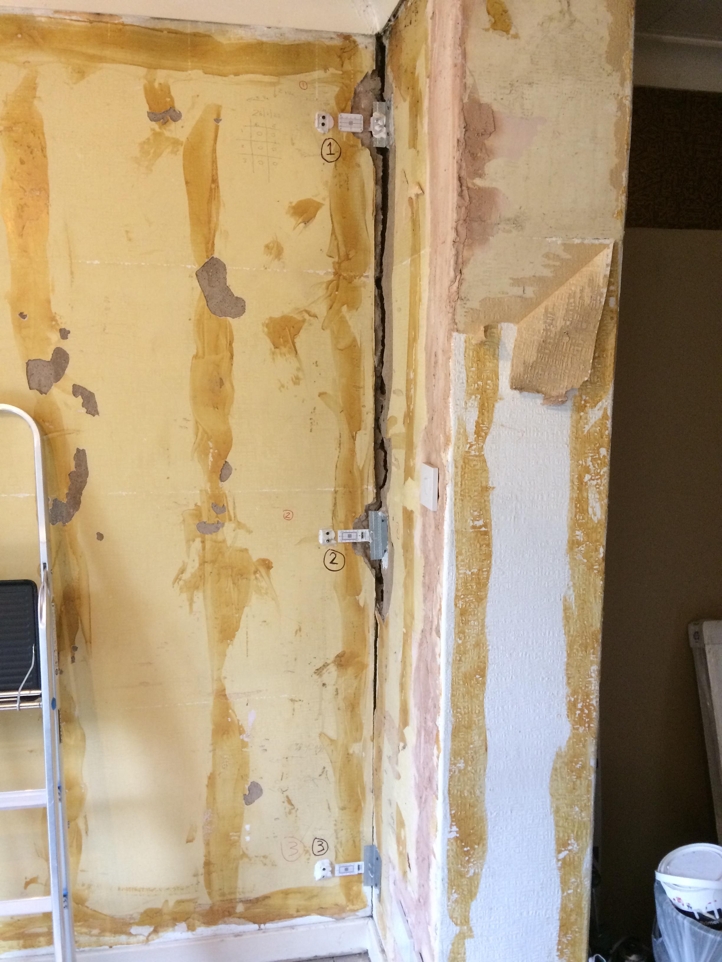
Update on Guses tell tales. Week past Monday I went back to take the locking pins out the tell tales, now they are free to move and the adhesive has set. On two of them the locking pins were binding fractionally. Probably does not mean much as the fixings were probably settling in. I'll wait and see what things look like in another couple of weeks. Have asked the Client to keep an eye on them too and if they see movement to give me a call. That said I warned them not to look at them every day as they will start to live in your head.

-
RAAC autoclaved concrete, what about mannock blocks?
Gus Potter replied to CalvinHobbes's topic in Brick & Block
If your blocks are designed as a normal unreinforced masonry domestic wall then they are a different animal from the problems you see in the press. The problems you see published are when aerated concrete is used in combination with steel reinforcement so they act as beams. Have attached some info from the IStructE for some bedtime reading.. so you can hopefully sleep ok. RAACs-v3.pdf -
Have come across this from time to time. Yes your starting point here is to intially forget the soakaway concept and go for a packaged treatment plant. The cost of these has come down a lot over the years. 300 -400m is perfectly doable to pump to a water course.. you may find that a 40- 50mm diameter pipe works fine. It also does not need to be on a fall. I designed one a while back down Aylesbury way where the pipe went up hill first then down to the water course. The main thing is the dry weather flow in the water course.. SEPA do that bit of the work for you.. so you need to make any offer on the plot conditional on SEPA giving you the OK. The application process is faily simple and not hugely costly, but it takes a bit of time to get SEPA to process it. But I would try and lock in the seller early.. don't tell then just how you are going to resolve the problem in case they do it themselves and gazzump you. Also a PTP does not need to be buried in the ground. If the house is higher and you can get a fall to it then fine. Another way is to gather the soil water from the house and pump it up into the PTP a bit like an external saniflo.. but much better. . You have options here. Yes the plot is worthless so the Estate should be fine (unless they want to knock off 40+ k of the value of the plot.. subject to conditions).. all you need is 750m deep track to bury the pipe from the PTP to the water course. You could maybe do a mound soakaway but these are costly to design.. lots of liability for the designer. A mound may cost 20k+ to get it right.. even then the topography of the ground and area available may make impossible.
-
Good question @George There is a bit more to this story. It started with the Client asking me round to have a look at upgrading a rear extension built say 30 years ago, badly, so it is done now... leaking heat, windows and doors beyond repair... flat roof .. no / negligable insulation. On the end of the rear extension there is a conseravtory that is done but has what look like a good found. Putting my Architectural design hat on I was thinking of knocking down the conservatory down to dwarf wall level and incorporating that into the upgraded extension. For me there is the structural design, calcs etc and the Architectural side. I wear two hats so that allows me to provide a one stop shop. When I went round to first meeting the Client I spotted these big cracks. After talking about the Architectural opportunities I started to discuss how with my SE hat on I would make it all work. At that point I said.. I won't do the job unless we can understand more about the cracking. They told me that the neighbours (semi detached house) had just slapped out their rear elevation and put in a "goal post frame".. I'm thinking I bet their SE has not thought this through and not provided enough detailed drawings for the builder to follow. Maybe I will be pleasantly surprised.. but from experience I know that SE's under the Scotland SER scheme are cutting corners... and I don't want their bad work putting my Client at risk... and me also. The Client mentioned that Network rail have been working near their property.. but I know the location, nipped round to have a look at what they have been up to and concluded that none of their retaining walls have shifted such that they could have impacted on my Client's property to any significant degree.. I had a look at possible ground vibration.. again.. was happy with that. Now given that I'm doing all the design work for the project I itemised the tell tale installation and crack monitoring out at £600.00, I don't charge vat as below the threshold. The tell tales cost about £100.00 ( bits and bobs and me driving about), I allowed £300.00 for my day to install and I'll tie in the monitoring with my visits to do the dimensional survey and when I meet with the Client as part of the usual design process. It will take about six months to do the design / planning and building permissions.. nothing happens fast with the council... but six months is enough time for me to get a feel for any significant movement.. before the big bucks get spent. I have explained all this to the Client so they are fully on board with the approach. They know that it is not perfect but we are doing the best we can in time we have to a avoid a catastrophic outcome... This job is a little different as normally I would often monitor settlements over a longer period of time. But here my gut feeling is that the cracks are long standing and pretty much stopped moving.. but I have my doubts about what their SE / Builder has been doing next door. If they have made a mistake then I should be able to clock this pretty quickly before my Client starts their work.. as soon as they start the neighbours could blame them and me and they are off the hook... as last man on the job gets the blame... or has to prove they are not.. very costly potentially. If I find things are moving then I would dig deeper.. maybe phone up the SE for next door and say.. I'm finding this.. do you want to have a chat? I can't expose my Client to this risk. The rates would be different if it was isolated settlement monitoring.. much will depend on the risk element etc. For me as I'm in at the start of the job and designing it I can make sure I stay away from things like big point loads in vulnerable spots..close to party walls etc so reduce risk that way.
-
Noninvasive flow measurement
Gus Potter replied to Beelbeebub's topic in Air Source Heat Pumps (ASHP)
Yes that would work I think to help you identify the loops that are not performing... which is what we would do normally.. we just walk round the house and put out hand on the radiators.. and go.. hey.. that radiator is not working that well. But if I was going for a 10k plus heat pump I would want to know more about my existing pipework so I don't get shafted by the installer. -
Assume they are off the xmas card list and on the "I hope it goes shit for them next year" list.
-
Lots of good points regarding type of grinder but preparation is the key to a good job. I used to be a builder before I got into SE stuff so here is how I would cut a raggle in a nice stone wall that is compliant and is going to look good and professional. Stone walls often have a tendency to disintegrate when you start to cut chase for lead, but you want your lead work to look good and not leak. I would start by fixing a level bit of 100 x 25mm thick timber to the wall using screws and rawl plugs where I want the top of my chase to be. Next I favour a 9" grinder with a standard diamond disc, I think the kerf width is about 2.0 - 3.0 mm.. the kerf is the width of slot that the disc cuts. The 9" grinder has more power but is also much more controllable (I have two of these 9" grinders but only one smaller grinder for this reason) as it has big handle to grab onto and a bit of self weight that stops it jumping about. Mark the disc with a pen to give you the depth of cut. Go for 25 -30 mm on average into the stone if you have a good thick wall. Now you have to judge this as the stone will not be flat but you are looking for a penetration into the stone of 25.0mm to comply with the regs.. and the Cookson / Calder good leadwork guide.. which is your Bible on this. Download the Cookson or Calder guide to good lead work... if that is the only thing you do... it will save you money and grief! The main thing is that the depth of cut will vary.. this is because when you come to fold your lead into the chase it needs to be straight to look good but the wall will be in and out a bit! That is part of the reason for the 100 x 25 timber. Next move your 100 x 25 timber down by 20mm and repeat the above. You'll find that the timber has "suffered" a bit when you cut the top but that is ok, and that is why I cut the top chase first.. which is the bit you see. Now you have two cuts in the masonry. Get a chisel and carefully break out the stone between the two cuts and clean the back of the chase out, then brush / clean off dust. You should now have a cracking good looking chase for your lead that has not damaged the stone. The next bit is preparing the lead flashing and fixing it into the chase. This is a diferent skill and can be done in a couple of ways not least. With my traditional hat on I use little strips of lead rolled, folded and wedged in to anchor the flashing, then point up with mortar to seal completely. The flashing need a good bit of preparation so you have a task ahead if you want to start dressing and folding the flashings. How you fold the lead into the chase is really important. I could try and describe but it would take ages.. try looking on U tube. This is a skill that is passed down the generations, I learnt it form a lead worker hands on... It's not in a book! See the Cookson guide. I form the bends that go into the wall a bit like a cavity tray... hard to describe here without writing a massive essay. I think if you are asking about a grinder size and discs then you have a bit more to learn about how you do these flashings to make them last and water tight. Lead working is a skill that takes many years to perfect so please don't take this the wrong way. Keep asking questions! If you do this and grasp the basics then your grinder question will resolve it's self. One last thing.. make sure you get Patination oil and treat both sides of the lead or you will end up with massive stains down the roof!
-
It's a fair point until you look at the extra cost particularly labour wise of installing the glass wool under the warm roof. For the glass wool layer to work properly it needs to be really carefully fitted and that take time = cost. Can you just make your PIR 200 mm thick and it will have probaly the same effect as you do away with the repeating bridges of the roof joists. I have done this on my own house where the warm roof is fixed together with glue not mechanical fixings. But lots of folk want a mechanical fix.. finding the fixings it a bit tricky for 200 mm PIR.. but it can be done.
-
In some cases it is perfectly legal to bury asbestos. But why? Well, I'll take an example. Say you have soils containing mercury or say chromium. Now once you get a handle on this and you weigh up the the risk of disposal vs burying you find often that burying is the way to go. The same rules apply for asbestos pretty much. Asbestos is actually a nice thing to bury as it is inert and does not contaminate the ground water where as Mercury and Chromium does. Remember that asbestos often comes out of the ground as a natural mineral from Austraila. There was a court case in England where contaminated material was taken off site, it blew off uncovered lorries and polluted a load of villages along the route to the waste disposal site. It was really bad, kids suffered. There are a surprising amount of houses that have been build over the last few decades where the top layers of soil have been stripped off, the contamination buried deep, a membrane placed on top, the removed soil placed back on top of the membrane and house built on top of that. We do this in the UK and there are examples of this being done safely worldwide, Australia is one case I know a bit about. When I mean deep.. I mean deep.. so you home owner can go digging it up accidentally. 1.8m buried depth is a good number for burying asbestos. But if you want to do this then you need to have a contamination strategy, a risk register and other documentation that you need to include in your deeds. If you don't do this then you are breaking the law. You may find that to do this right that the cost of compliance is greater than just getting in a licensed asbestos removal contractor. Also remember that it won't look good to the average punter if you want to later sell your house. In summary.. Yes it is legal to bury asbestos in certain circumstances. You are not the "devil" You could chance you arm and just do it.. but see if you sell and get caught.. you are looking at a potential massive liability.. and your insurance won't cover that. I would play this off a straight bat and do it right.
-
Noninvasive flow measurement
Gus Potter replied to Beelbeebub's topic in Air Source Heat Pumps (ASHP)
By all means give that a go. Much will depend on you enthusiasm for getting stuck into this bit of your project and if you have the time to play about with it. In the last post I mentioned doing calculations etc. But if you want to just check that your loops to each rads work ok ish then you could just do the first part with the hose thing.. that at least will let you identify any really bad loops if there are any. The heat pump thing is a big outlay. How are you on diy plumbing? if you want post some photos of the boiler pipework you have and folk will chip in as to how you can break into the pipework easily using DIY plumbing fittings. Oh I forgot to mention. If you are flushing the system to investigate make sure you top up the inhibitor to keep things ok in the short term. -
Good question. Hard water often occurs when the water that comes in from the mains supply is extracted from a chalk aquifer or run off from chalk bearing soils. The South Downs are a good example of this. This makes the water that comes into your house a little alkaline and it has a lot of mineral salts in it too. In parts of Scotland the water is off peat soils which makes it a little acidic. What folk do is to have water "filters" that compensate for the alkaline water and capture the mineral salts.. so your kettle and hot water system don't get firred up. In Scotland in peaty areas the water can be a bit brown when it comes out the tap so the filters clean that up a bit. But in both cases the PH value is close enough to 7.0 so as not to impact on the bacteria in a septic tank. However.. if you are talking about the things you hang on the side of the toilet then they are toxic to the bateria in the septic tank, just like toilet bleach.
-
Noninvasive flow measurement
Gus Potter replied to Beelbeebub's topic in Air Source Heat Pumps (ASHP)
A few random thoughts from me. If you are upgrading to a heat pump than that it some serious expenditure. I would want to make sure that my existing pipes supplying the rads are clean as I can get them so that means a good flushing... which is kind of what you are thinking about.. making sure the pipework is able to support the heat pump system. What if you start by flushing your existing system and where the flush water comes out attaching a filter ( magnetic) so you can see how much crap is in the system. You can use the mag filter later on anyway. This is good for the sole not least. Next if you get a hose pipe and run that off the mains water supply to where the outlet of the pump is going to be then you can measure the flow rate that comes out the hose with a bucket. You could do this with three rates of flows out the hose. Call this the inlet hose... the idea is you calibrate the flow rate out of the hose. You could just use a gate valve and say.. one turn open gives me x litres per sec.. two turns y flow rate. Just check what pressure variation the waterboard supply at.. could be pretty constant if you do it the same time each day. Next isolate all the rads (which you are going to change anyway?) apart from one. Put a pressure gauge on the flow just after the existing pump (flow side) so you know the pressure just after the water from the hose enters the system. Buy gauges that you are going to use later. Attach another hose to the return side close to say where the return for the boiler is and run that into another bucket outside. Attach a pressure gauge here to just where the water comes out the return side so you don't capture the losses in the exit hose. Now turn on the hose and measure the flow rate and pressure on exit. I have to go back to my Hydraulics for the equations but if you know the inlet pressure and the exit and flow pressure you can calculate the losses in the loop you are examining. Do this for the three different inlet hose flow rates you have calibrated the hose for. In terms of flow what goes in has to come out the other end so I think from memory you have three variables and from that you can calculate the losses in the loop you are looking at..the losses gives you the head loss in the loop which you need to size the pumps etc. If you do this with the three different flow rates from the inlet hose it lets you then see how the different inlet pressure = pump head which impacts on the performance of the loop. Now you know about your existing system with the rads you have. If you swap out all the rads then the short bit between the rad inlet and outlet should not make much difference.. its the pipes that you need to know about and if you change the type of TRVs at the rads. But if you swap all the TRVs for the same type it just shifts all the loop resistances by the same amount.. which you can adjust when you put in your the Heat pump system. The next bit is the hard bit maths wise. You now know the loop resistance of each loop when all the other rads are turned off. Go back and turn them all on and repeat the above but with all the rads open. This will give you the head loss for the whole heating system. If you then compare the losses for each loop (with all the other rads off) then you should be able to see if you have problem loops. Then you can work out what to do about that. But you also now know what the head losses are when all the rads are open.. so now you can start to design your heat pump system based on this is the worst it is going to be. You are going for larger rads and so on. The upside! 1/ You'll need or need to learn some basic plumbing skills. But if you do this then you will be well set when you come to look at the plumbers work, have a sensible discussion and keep costs down. 2/ You will get a huge amount of enjoyment playing about with it, even if it's just a case of cleaning crap out the existing system.. you'll save some money for good use later and learn enough so the plumber does not take the mickey out of you. 3/ You may find that you don't need a HP at all and can splash out on other things.. -
Insulated twin pipe, 32mm or 40mm
Gus Potter replied to HughF's topic in Air Source Heat Pumps (ASHP)
I wonder.. if you go back to how an old back boiler in coal fire works. Hot water rises, cold water falls.. the old back boilers could set up a good rate of convection flow. What happens if you apply these basic principles to you modern flow and return.. thus that means you put the pipes in with a fall so you are not fighting against the natural convection.. mind you think I might be splitting hairs here! Main thing for me would be to look say 20 -25 years ahead and think.. what if the pipes silts up a bit or I get a daft plumber in that lets unwanted bodies into the pipe. How easy would it be to flush it all out? Given the cost of excavating and preparation I would go for the larger pipe diameter 40mm as once in it's "there for life" ? -
A lot of good points and observations made here. Yes agree with all it does look like there is another roof framing in which will add a bit of a point load to the purlin. Also as others have noted there is a knot, shake in the timber right at the point of maximum bending stress. The purlin is something that can often be fixed. But you can see the roof must have dropped.. so that suggests that the roof may have spread, including the bit of roof coming off the purlin. I would want to understand if the roof has spread and if so what damage if any has been caused. Some roofs spread and don't impact on the rest of the structure too much.. at times spread can cause havoc = money. Often with something like this you just aim to stop further movement rather than trying to jack things back into position as jacking can often cause even more damage. Sometimes we want to add a bit of prestress to a remedial member. For example if you bolted a new bit of timber to that purlin before the new bit of timber starts to work it needs to carry load thus for load transfer to occur you need more movement... which you are trying to avoid. What you might do here is see if you can get a good length of new timber into the attic that spans nearly wall to wall. Bolt it in the middle where the existing purlin has split then jack the free ends of the new timber.. you pre stress it. Then finish the bolting and use some brackets or equivalent (there are some clever ways of doing this that don't require brackets per say, these work like gallow brackets but much more refined and made out of timber) to fix the ends of the new timber to the masonry.. to take some of the load and help to stop things from twisting. This is a bit of a simplification but hope I have conveyed the principle of my thinking. The main thing is to really examine the rest of the house for damage caused by possible roof movement, if none then it's down to just fixing the roof in a practical and as simple a way as you can find using off the shelf materials.
-
Yes it is. I have got into assessing roofs for PV in terms of making sure that they are still safe SE wise.. I ask questions.. Big learning curve and yes it is like the wild west. The problem I have is that once I explain what needs to be done to make the roof safe and water tight then a lot of the honest PV folk can't compete as it is a race to the bottom. Some roofs are fine and can take the extra loading. Many old roofs are already over stressed when compared with modern design codes but sometimes you can still make things work with a bit of pragmatism. My problem is that a lot of PV installers have no clue about what they are doing. Well a lot do and they don't give a jobby... it's a case of what can we get away with. Never mind the SE side.. lots of PV installers will notch the tiles to get their brackets in. If you go back to Marley tiles who stand by their 50 year warranty on their tiles and ask them .. is it ok to cut notches in your tiles and reduce the lap.. they will tell you.. (expletive deleted!) no. If they could reduce the lap they would have done so decades ago as the market is so competetive. If any PV supplier can't answer these basic questions that could compromise your house then why on earth would you part with several thousands of pounds to get a bit back on you leccy bill? For me know knowing a bit more about the PV market.. under the bonnet... oh dear! Hopefully things will pick up in terms of transparency ect.