Gus Potter
-
Posts
2339 -
Joined
-
Last visited
-
Days Won
29
Everything posted by Gus Potter
-
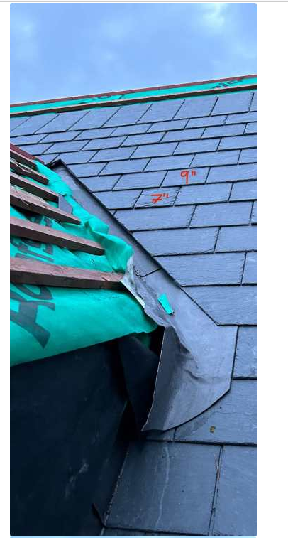
Slate and a half in valleys, advice needed.
Gus Potter replied to bluebellcottage's topic in Roofing, Tiling & Slating
Slating is an art and traditional craft. It gob smacks me how often folk claim to be slaters but don't realise how slates in valleys and at roof verges need to be tailed. It not just for appearance it has real meaning to prevent dripping and compromising the lead in the valley and the verge. When cutting a valley slate you pop it upside down and cut the tail the other way up so the regular rain water does not drip on the the valley lead.. is uses the miniscuse principle and trickes down to the bottom of the valley where the thick lead is. These are traditional skills. it also protects the sharp edge of the slate forom frost and maitenance damage. The natural bedding plane of a slate is not suited to getting cut by a diamond saw! At the roof verge we do the same so the water is shed back into the roof rather than rotting the verge. These things are the basics of slating that were drummed into me and apprenticies. Folk think.. hey I've got a slate roof and it will last longer than concrete tiles.. well it won't unless you know these things! Whoever slated this valley is not slater and you would not get anywhere near my house!
-
I love the amount of work you have put into this as a concept. This is improtant as you have sat down and identified the type of house that would suit you and the internal spaces. For me Perthshire is stunning. Some of my family lived in Perthshire the rest now on the inner hebrides.. the white beach is the end of their garden there is no fence just the sea. The critical thing is the services and that is going to have a big effect on the overall build cost. Once you start to live in rural Scotland there are other costs.. travel.. just to get a pint of milk.. don't underestimate these. Take your car for a service.. you may not get it back for a week! But the land prices in Perthshire have rocketed but olocal services are still expensive. What is still affordable is Argyll for the self builder on a budget.
-
Hiya. There is a lot of well meaning advice here in the posts above. I do this as a day job and you are inviting trouble. I see this all this time and folk end up in a nightmare! There are maybe one or two SE's on BH who know about this stuff.. the rest are.. it's not their day job. I can't see all of the roof truss layout but I'll hazard a guess that some of your intermediate walls are non load bearing. Now it looks like you have ground floor extension with a beam over.. if you change the loading pattern you could over load that beam for example that allows access to the extended part. You are playing with fire here. Just say you come to sell the house and a surveyour sees you have made alterations to the attic. You won't be able to sell the house... even if you think your alterations are sound. You'll need an SE to sign it off. Please do this right and pay an SE for advice. Aye but this is let's say putting a bit of a gloss on things more often than not! If loft zone want to get in touch with me them I'm all ears! I would love it if they have a good economic load bearing and compliant solution as I could sell this day in and day out and sign off on it too! I keep pulling these folk up about the shite they are selling for say fink truss aplications. Some of them approach me to sign off their designs. OP and there are a few of these loft boarding folk proposing insultating with spray foam insulation so we need to have a look at the dew points so your roof does not end up rotting away! Now your basic distributed design load on a modern lightweight roof truss is 25 kg/ square metre applied to the ceiling chord. There are other loads but for now. Add 11 kg/ m^2 for your flooring leaves you with 25 -11 = 14 kg tops depending on the truss spacing.. Most of then are selling on the basis of 25kg.! Now take the insulation wieght off this. Then go back to the truss manufacture and ask.. can we insulate out our loft and floor a bit of it.. if so how much load can we put on the new floored bit! Now some of these loft folk are saying.. we can give you a bigger hatch.. now you are cutting a structural truss. Just look at the sizes of the bit of wood! Even as a lay person you must be able to see they are slim and slender. Now just say you are going on holiday to Spain and the window in the airplane is a bit small. I pitch up and say.. no problem pal.. I've brought my Dewalt and I'll just cut this tiny wee rib out as it is so small it can't be doing much, fit a new window bigger from B & Q and you be good to go!
-
Hiya. Happy to give you advice where I reasonably can. But I need to see all the drawings, a panoramic set of photos of the house, any adjacent houses and all your drawings and ans SE calcs you have. Without that information can't say much more as no one else can on BH. If you take the plunge you'll get loads of help from all sort of folk.. from SE's and seasoned builders with 40 plus years of exerience for example.
-
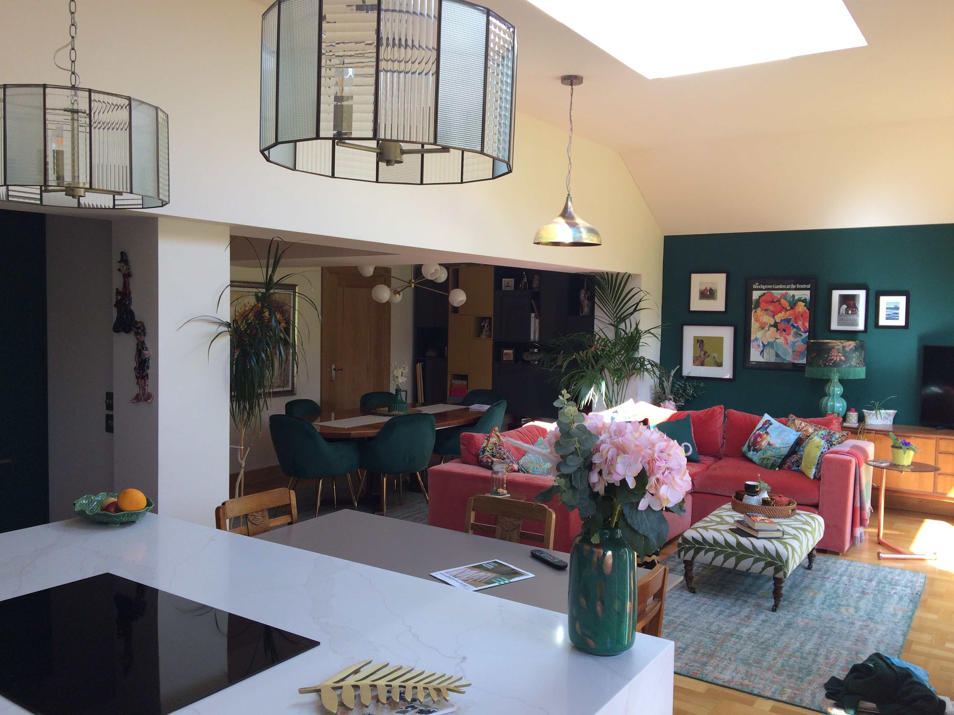
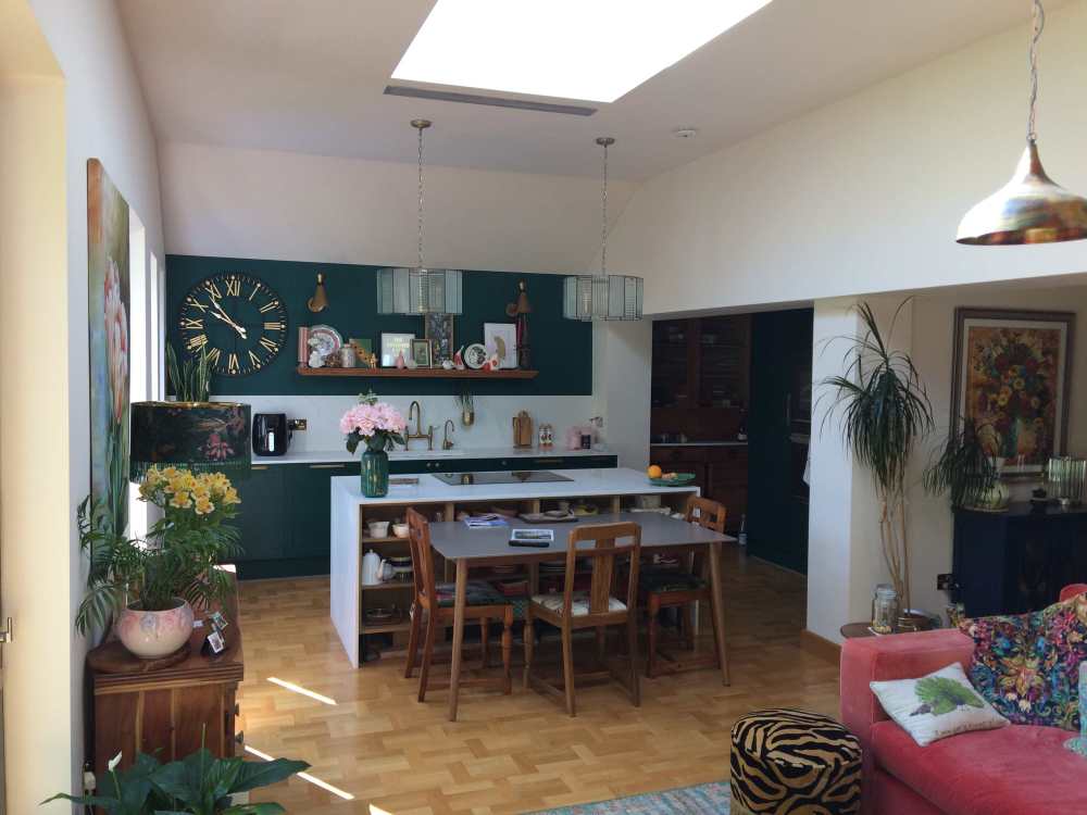
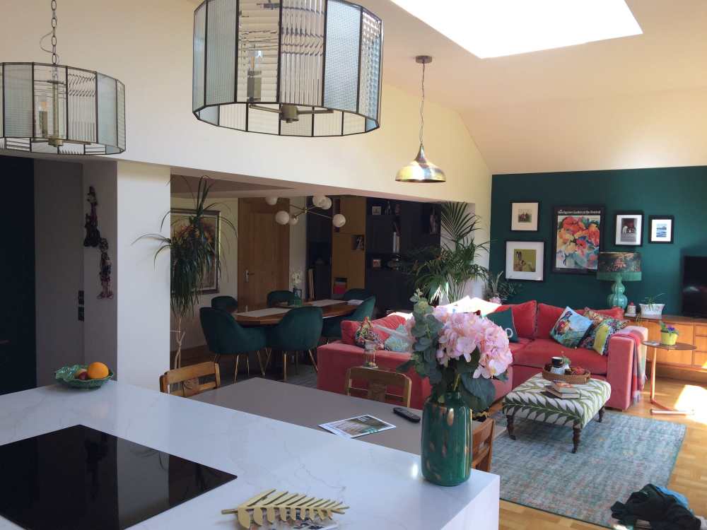
Here is part of my structural work and my wifes interior stuff.. we have yet to finish it off. This is an ex council house that we have extended in East Kilbride. The photo below is taken from my old phone so take it as it is. Key points we resolved. The hob is in the island. The grill in the ceiling is connected to a 125mm duct and the extraction unit fan is mounted outside in the external soffit. The fan I robbed from a Client that was chucking away an old kitchen extractor.. and delivers 600m^3 extraction.. is sucks like a devil and is pretty quite. The two pendant lights you see over the hob will set you back £ 500 plus.. but when offset with a standard extraction unit the lights were a bargin. What you see is part of an open plan space. I started out as a builder.. then became an SE and evolved into a "desinger". The challenge for me is to marry good practical design with good cost effective engineering at an affordable cost and do something special! Now over the last couple of decades I've seen folk wanting these massive open plan spaces as these have been all the rage. But for most families with two kids and a dog they are not that great. Kids and so on want much more pricacy for example.. our work patterns are changing. Our house is designed so that the social spaces are clearly defined. We have opted for other spaces that allow us to work from home, have a space that is entirely different. It's not for all but it is worth a think about. Here is a diferent view. The wall cabinets at the far end are from the 70's and sit off the floor.. The dining table is rosewood with space for 12 when extended.. the chairs contemporary. While the interior design may not be to your taste some key features are the shadow gaps in the vaulted ceilings. I set them myself and did the plastering but it allows us to easily change the decor in a weekend. You'll notice some boxes in the ceiling.. there are some pretty big steels hidden there.. but we accepeted that and use the boxing in of the steels to define the different spaces all be it open plan. Pick a kitchen that is not going to go out of fashion. Mine can be easily changed! Gray is not a good investment. If you look at my photos it may give the dry heaves! but think.. how easily could Gus strip that down and totally change the theme in two weekends.. and that is why I do this as a day job and you could be left with a crap gray kitchen!
-
Topographic survey question
Gus Potter replied to Lincolnshire Ian's topic in Surveyors & Architects
Well done Ben that brief looks pretty good. The cost is middle of the road. Yes you'll need to pay the vat but hey ho. Make sure you meet them on site. Come armed with tea/ coffe and buns and a list of anything else. If near a road get some level of manholes etc, water toby cover levels and so on. Seriously and extra hour or two on site at this stage can save thousands later. From my end once we get into the detailed design we often need levels for obscure things.. it causes delay an uncertainty. Uncertainty = added cost and as designers we need to be conservative when there is a lack of quality information. Most folk want to help and will spend extra time if the Client engages. You can also get the gossip! and that can be invaulable later on. The gossip is things like what other sites have you seen nearby when work gets underway.. the ground.. who is the water board guy.. is he / she a wanker or pragmatic? As an SE I often refer to annecdotal evidence to back up some of my design decisions! If you feel they have engaged offer to pay a bit extra! Usually folks will say thanks but don't need more money! or just say and extra hundred in cash will cover it! To put this into context.. if you can save one day for a chippie or ground worker on site at £250.00 per day you get your money back! At this stage of the design you want to aim for the best quality of information you can get. I see this all the time on BH where folk skimp at the beginning and pay dearly later on. I'm not pelting folk self building as have done it myself when I was young. It is really hard to get the basic design info cf going to TF companies and so on for a guide price adding up the sums and hoping for the best. -
The right compactor for Geocell floor???
Gus Potter replied to eros_poli's topic in Tools & Equipment
Well done you for going for Geocell. I've worked with / designed for another member on BH using this as an option to EPS / XPS but in a slightly diferent context. All reports back so far are good! Can you post some detailed drawings and your target U values and edge details of what you propose. To be clear.. that means all the details. I'm interested but I'm not here to guess about what you want to do.. it's part of my day job as an SE and hobby so if you want a hand then please provide more quality information. Just as an aside.. The WYE system here: https://www.mikewye.co.uk/product/glasscrete-floor/ Is for a breathable floor. Now if you are on clay and you compact the shit out of it then you no longer have a breathable floor unless you ventilate at the sides big time! Love what you are doing, excuse the brevity! -
Great comment. I'm working with someone at the moment who has decades of life experience, a technologist who can easily grasp both structural and Architectural design concepts. They are managing the design process very well. I'm chipping in with a bit of SE design stuff and being a bit of a devils advocate in terms of the over all design elements of the project. Also like many self build the design evolves particularly say in terms of drainage / buildability = cost. I think it can be helpful to have someone who does design as a day job who you can call up and chew the fat with.
-
Just asking.. any chance of a free pizza?
-
No I've not. Your comments can be viewed in different ways. There is a fair bit of hostility on BH towards Architects on BH. Lets leave it at that and have some fun designing and doing stuff.
-
Topographic survey question
Gus Potter replied to Lincolnshire Ian's topic in Surveyors & Architects
The key here is to talk to the surveyor.. tell them what you want to do.. take their advice and offer to pay a bit more and ask them if it is worth paying a bit extra for a bit more service! For a bit of context.. when you get round to tendering.. one experienced operative on site can cost 1.0k plus a week... an extra £300.00 to the topo expense can really save you a lot of bucks. I've been on BH for a bit and totally appreciate how hard it is to nail down build costs. Everyone want to break things down into work packages.. like you are shopping in Asda. Self build does not work this way any longer. The people aspect is key to driving down cost these days. That takes time and effort... like serious effort and it is a massive learning curve to even get a grasp of the basics. BC, planning delays are costing us a fortune, I factor in now a dealing with "twat time" in terms of planning and BC interaction. TF companies etc are having to watch their costs.. and are delivering less on the design input.. eventually they will start to realise that service is the key. I see this as an SE. I totally get the excitement.. wife and I were away for my 60th this weekend.. passed by a distressed plot and she said.. let's buy that.. I'm like.. ok but let's make sure we don't loose our shirt!. Now what happens is I do an absolute pile of research and dilligence that I do as a day job anyway. But folk on BH often don't want to pay for that or expend the time learning about this.. and then find themselves in trouble. Years ago when I first started unless you were a complete idiot it was hard to lose money on self builds / flats / renovations / developments as property prices were increasing rapidly. There is much less room for error now and if you want to make a go of it you need to put in more work. It's shite but the rewards are worth the effort. Getting prices from kit companies, ground workers, sparks etc is no longer good enough as they are getting pelted by market forces.. they are putting too many caveats on what they are doing and it does not work as well now for the novice self builder. I'm still thinking about how I can explain in a better way of executing the mechanics of this in the current market. Post for another time. -
I've followed @ETC for a while and he / she have contributed lots to BH. I've learnt loads from ETC. @Bozza wind your neck in and look at the contribution @ETC has made to BH, the time spent helping folk and the experienced based comments that ETC makes. I would at the very least get in touch with ETC and sound out!
-
All comments accepted. I went a bit overboard right enough. Interesting you are an Engineer that now flies for a day job... how did you get from A to B? There is another member on BH that does the same as yourself. Great bloke.. attention to detail is impressive. One of my family flies fast jets.. retired, appreciate the way you filter stuff. Golden rule seems to be.. don't crash. Well done with the oven.. it's all about the food.. who cares what the render looks like.
-
Aye ok.. true but what gets my goat is there are loads of folk advising on structural fixings and it is clear to me that they have no clue about the implications.
-
This all is happening in real time. My thoughts are to see if you can rack up expense for your neighbour as they have got all aggresive. Turn the tables. I would want to have a look at their foundations to see it they are relying on your land for support. Now we can make hay here as often builder never follows the foundation design when close to a boundary. You dig a hole and make them prove they are not relying on your land for support.. and that costs a lot SE wise and no SE is going to sign that off without a full investigation. I would check to make sure that they have the required fire boundary protection in place. I would also check any drainage runs and so on. Have they built over a drain that is serving more than one house and do they have build over permision for that? 80% of the time folk don't! They will shite their pants! This is a big lever. If they have done this with no build over permission then they are (expletive deleted)ed. Do their gutters over hang you property for example? Do they have an extractor fan vent to close to your property? In summary often we can find things that are non compliant on their side.. If you can find a street wise deisgner then they can maybe make this problem all go away. For me I would see where the land lies and if it look promising under your instruction chap their door and spell it out to them as an independant advisor, advise them (impartially of course) that they should seek professional advice as they could loose their shirt if they persist.
-
Hi all. There is lots of talk about concrete screws. But it is apparent to me as an SE that you have no idea of the loads that you may be supporting and the different behavoir of the substrate you are fixing into. Unless you are aware of this and the compressive loads from above, masonry bonding and the fact that a lot of concrete screws off the self are not stucturally rated then you need to shut the (expletive deleted) up as your comments are dangerous.. and stop giving advice that could miss lead the novice to Build HUb. if you want to suggest other fixings then I'm ears..
-
D.I.Y or let someone else do it?
Gus Potter replied to Russdl's topic in General Self Build & DIY Discussion
So cool.. only a lord of the sky could come up with that.. see Narcos! -
'How to sort it tips' from joiners please?
Gus Potter replied to saveasteading's topic in Barn Conversions
Ok it's not worked out that well. If you are embarking on a big TF stick build project then you need a saw bench made from timber with a good top quality chop saw. You fix solidly the saw bench to any floor and at night you take the chop saw home so it does not get nicked. Expect to pay around £700 - £900 for a good saw and blade. On a big kit you need a saw with a 300mm blade that does compound cuts. Don't mince about. This way you can fabricate a TF frame to the same tolerances as a TF fabricator. OK so you are not 21 years old any more. Making Tf panels if working on you own.. on site and lifting them up. You square the panels with the odd OSB board. Then lift them and sheet after. To stop the sheets dropping you use a temporary ledger at the bottom and then tilt them into place. Now I'm an old codger I've figured out how to stick build a TF for the folk that are 60 plus.. and have done it myself. -
Yes that sums it up but also the ground swells up.. some grund can swell / shring a lot.. several inches / cm! Things like trees and the desication of the ground are essential to know about. Nick makes a good point here. If your motivation is to achieve something close to passive then a raft is a good simple way of doing it. Yes the raft may cost a little more than a strip found but it can be much easier to build in some circumstances.. it's simple if you take care and lay the insulation and rebar correctly. All these things come with a lot of complexity. Say you are in a Radon area then a raft makes the Radon Barrier easier to detail out / buildability for example. Trees for example in clay soils can make things much more complex. But just say you have good ground and just want a raft as Nick favours and because YOU CAN and WANT IT.. no harm in that.. it's your house and your design decision. If you have good ground then this can be easy to achieve without chucking loads of rebar at the slab and making it massivly thick. You need some kind of floor anyway! It usually needs a bit of edge thickening in some form or another as folk want to put in big glass doors these days which cause point loads at the slab edge. One biggy that BC / NHBC ask about is cover for frost and height to DPC. Generally height to DPC from ground level for sensitive wall cladding is 150mm which is about 50mm less than the thickness of an ideal raft slab on good ground. Now add 300 mm of EPS to that takes you down to 350mm below finished ground level. Add say 150mm of type one and now all our materials (which are not suceptible to frost) extend to the min of 450mm required for frost cover. Box ticked. For all.. Raft slabs.. and a bit of info that may help. There are argueably three at least kinds of generic rafts. Within each type there are permutations. There are others but let's run with this for now. The main types are: 1/ A rigid raft. This tends to be a bit of a beast. We may use this in a domestic context where we have past mining that can cause the ground to move / crack horizontally at the surface. This used to be associated with long wall mining where you get a rolling wave of horizontal movement in the ground. We don't often design this way now in a domestic setting.. as they shut all the mines long ago. 2/ A semi flexible raft. Here we thicken the edge a bit but if you have heavy walls the EPS say at the edge compresses too much which causes the edge of the raft to rotate. To stop the rotation we reinforce the slab so it carries some of the vertical loads and stops the rotation of the edge. 3/ An edge thickened slab. Here the thickening at the slab edge deals with the frost cover and the differing line and point loads around the slab edge. The slab it's self is just designed so it does not crack thus has a light reinforcing mesh. Now within all these generic types there are permutations and the design is often driven by how good and consistent the soil is under the whole thing. If we have ground that has local soft spots then the edge of the slab and internally often needs to be thicker so it can span over the soft spots and thus needs more reinforcement. In summary it's a pretty complex undertaking in term of the structural / soil things you need to know about . but the solution is often simple once you draw it out. The main thing is to spend a bit of time and money understanding and investigating your ground as this reduces your risk and helps you design the right way. With a fair wind a raft slab does not always cost a lot more when you take everything in context.
-
Ask what would you home insurance say! Do you think they would pay out if your only arguement was.. well other folk have done it? Builders often tell you what you want to hear not what you need to know.
-
You may ask what is @George on about.. ? to the lay person it may seem odd that when you remove load from a brick wall it can make it unstable. How does that happen? Imagine you have a brick wall 2.4m~ (8 feet high) That's about in old money 32 courses of brick. The mortar is old so not "sticky" thus it can only carry a downwards load. Envisage 32 bricks stacked up on old crappy mortar.. if you can. Now the wall is held in place by the floor and the ceiling at the top and above that by the rafters say. . Imagine if you gave it a sideways push.. ? For it to topple (basically) you would just need to over come the self weight of the bricks that are left for the wall to bend beyond it's "sideways tipping point" . But the chimney stack adds more weight which makes it harder to topple. You can try this at home with say Jenga blocks. Add weight to the top of a stack of blocks and they are harder to topple when you push sideways. Also if you remove one side of a chimney and use gallow brackets you can suddenly make things a lot worse as the gallow brackets cause a "toppling force" that is unexpected.. that is why for one reason BC have clamped down on this.
-
Hi Ian and all. I can see where you're coming from Ian but there are a couple (well a lot of steps actually) of steps missing. Generally Ian your right about typical slab edge TF line loading only being about a tenth of the load that a 300kPa insulation can carry at 10% compression. Say Ian's load is 10%.. that results in a settlement of 3.0mm at the edge of the slab say. Now it gets a bit more complicated as that amount of movement at the slab edge is on the boundary of crack / over stress the slab if it is not reinforced. For all G and J sum it up the concept.. sometimes we need to go back to basics! Simplistically we make a concrete slab that generally spreads the load over a large area and that all works fine. Take a 300 kPa insulation at 10% compression at 300mm thick. That's 30 tonnes per square metre on the face of it but it will; compress like fury, crack your walls, make your floors off level, burst cladding fixings, maybe cause the roof to leak and stop your doors/ windows from opening and shutting.. ! When we design foundations and raft slabs we as an absolute limit the settlement to 25mm for a domestic dwelling over a 50 year life span. Now it's not just the compressibility of the insulation it's all the stuff under that... the soil and so on which adds to the amount of movement / settlement. Take the outside walls for example.. these load the slab edge and thus at the slab edges we get an overstress / too much compression of the insulation. Simplistically we calculate what the insulation can carry at the slab edge. The bit it can't carry we throw back into the slab by reinforcing the slab with steel bars until we get it all to work. The technical term for this is what we call a semi flexible edge thickened raft.. The semi flexible bit is important as what we do is balance the movement / flexibility of the layers with the reinforcement and usually the insulation behavoir so the slab does not fail and crack too much. Now that all sounds complicated but all we are doing is to look at how "squashy" the layers of stuff are under the concrete and design the concrete raft to cope with that. In summary when it comes to EPS or anything like that think about how much it needs to compres by before it achieves it's declared strength.
-
I've used this in one of my designs..The Client was keen on it and wanted to make it work .. good results so far!
-
At the end of the day my gut feeling if you have trees is to go for a strip found if you can. You compensate by using more insulation elsewhere. The trees are a big thing. Can't say much more with the limited info you provide. The raft designs I do are nearly always goverened by the compressibilty of the insulation.. and I've been doing that for decades like Olaf. Tanners (TSD Ireland) also know their stuff, working with them just now. Look folks this is nothing new. Like Olaf and the Canadians putting insulation under concrete is not that hard. In Sweden and Canada the frost heave is a big thing.. in the UK we assume the frost only goes 450mm down tops. For insulated rafts we need to know how much each layer compresses by. If you take an insulation that states it has a 150-300 (tops) kPa compression strength.. that on the face of it looks like much more than a soil with a kPa of 75 -100.. but the fine print says that it will achieve 300 kPa at 10% compression. Now say the insulation is 300mm thick. You load that up and it needs to compress by 30mm to achieve its design strength. Now 30mm compression will play havoc with the concrete slab.! It won't work! When desgning these things I look at the soil first to get a handle on that, often I can put that to bed and just look at the insulation, it's U value and compressive strength at 10% compression.. Then the loads and flexibility of the slab.. see how much it can bend by without cracking and not needing daft amounts of rebar. I do a bit of juggling to balance the loads and the job is nearly done in terms of checking the structural strength. Unless there are point loads! Now the nightmare starts. You look at buildability, how much you can pour in a day, where you need joints for shrinkage etc. These are actually the hard parts! This idea that folk have.. you put insulation under a slab (to make it a passive slab) and now you need to be a specialist is a bit off the mark.. the insulation is just another layer above the soil with a different elasticity. Semi flexible passive rafts (a nuance but designed slightly diferently) tend to work down to soils with a bearing capacity of 40 kPa if the ground water is well down. The insulated raft is not often technically a challenge. The trees are important as these are the things that can add value, ammenity and don't forget.. things like shading! it looks like you are going for the PH concept.. so you have maybe lots of glass.. try if you can to look after the trees and not consider them as an obstical and take advantage of them. Can they provide shading when considering over heating in the summer. As an SE/ deisgner I look at the site.. what makes it attractive.. say the trees and then try an find a solution that preserves the character, ammenity and then see if we can say use the shading effect and greening/ colour contrast to enhance the surroundings.
-
Ok to disagree. My own feeling is that it's worth while paying the SE for a visit. This achieves a number of things. 1/ It lets the builder know that you the Client are not alone. 2/ I can say that I can't remember the time when I went to inspect a job and found nothing wrong. Builders often swap materials, hangers, connections, nail types and don't follow the nailing schedule on TF. Then you have fire stopping, vapour barriers etc... long list 3/ When I go to site I also look at fit up and if everything looks ok for the next stages say.. the insulation, how are the drains looking and so on. Now is the time to nip things in the bud. As a project goes on builders tend to come under more financial pressure as they like to get as much profit out the job early on. If they feel they have a weak Client it's human nature that they tend to let things slip as the project goes on. Ok @joe90 I agree with you that you should tell the builder to get it right.. but sometimes the presence of an SE, Architect or QS say can concentrate the mind..avoid later serious disputes.. especially if any visit is at short notice or unannounced.