lineweight
-
Posts
91 -
Joined
-
Last visited
lineweight's Achievements
Member (3/5)
9
Reputation
-
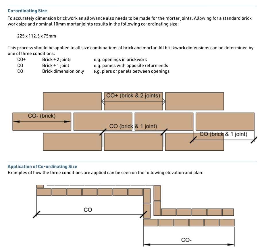
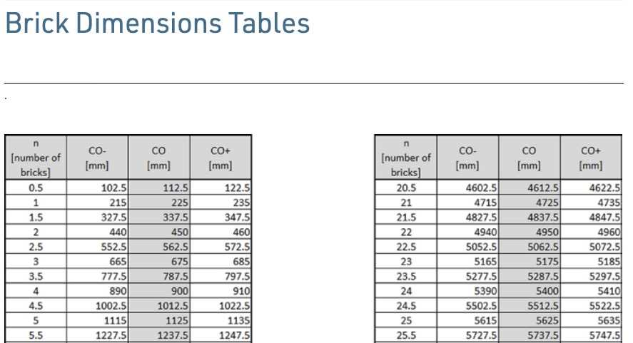
Thanks. I note that's assuming 10mm mortar joints. I am never quite clear how the setting out worked, pre metric sizes. A 228mm brick is 9 inches, but 10mm is just under a half inch. So once you have a run of 9" bricks with 10mm joints you are going to get out of step with any kind of even imperial measurements. So, is it the case they actually would have worked to ½ inch mortar joints?
-
The tables below are from the BDA guide. They give you the various co-ordinating dimensions that apply depending on how many mortar joints there are. My question: does anything similar exist for imperial (lets say Victorian era) bricks? Or were they never standardised enough for these kinds of tables to apply?

-
Yes it looks like you're right. I'm not that familiar with marmox but there are other things that do a similar job (assuming the main job is reducing cold bridging)... foamglas perinsul for example, and that is available in a 140mm high block. Looking at the original detail though, the marmox doesn't really look to be in the right place to me... shouldn't it be in line with the floor insulation.
-
Looking at the photos I don't quite understand this bit. The photos seem to show a concrete floor, but the top of the concrete appears to be only a little lower that the finished floor level. Where did the "timber beams" go?
-
My suggestion to use another row of marmox blocks was that you'd do that but keep the floor level the same. The second row of blocks would be behind the skirting board.
-
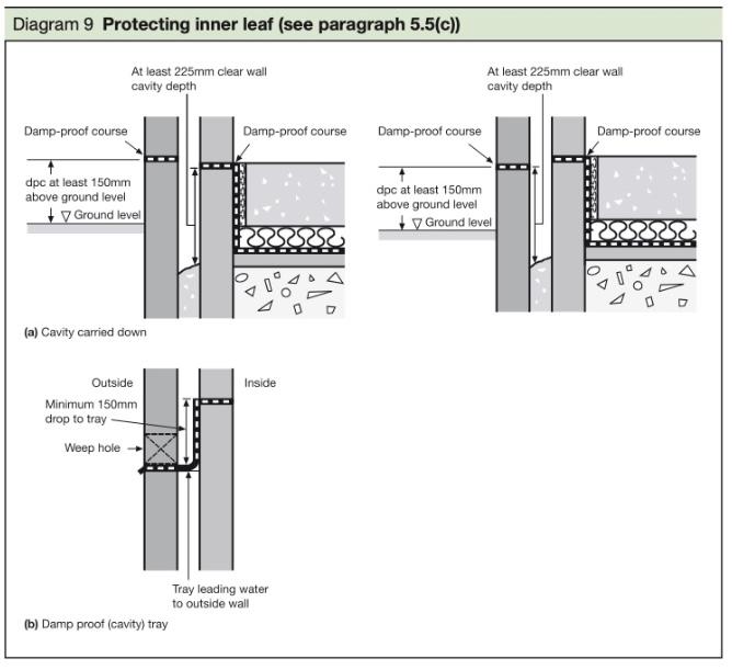
So, in theory can it be pushed down to the extent that the inner DPC is lower than the external ground level, as long as the cavity still continues 225 down below that?
-
No thoughts on this?
-
An extra course of Marmox Block could lift the timber plates out of the danger zone.
-
If that area between the gravel board and the base of the wall gradually gets clogged up with leaves, silt etc over the years, then won't that gravel board act as a convenient dam/retaining wall for damp stuff - potentially bringing the top of that damp stuff up in line with your timber wallplates, which is ultimately what you're trying to protect here?
-
The diagrams below are from Building Regs Approved Doc C. The one on the top left shows the inner-leaf DPC a little lower than the outer-leaf one. It implies that this is fine as long as there's a clear 225mm cavity depth below the inner leaf DPC. But how far can this be stretched? If that inner leaf DPC was at the external ground level, for example, then it appears that building regs are OK with it, but this somehow doesn't feel right. For example it would rely on a certainty that there was no bridging of the cavity in that 150mm zone of wall above the external ground level. What's your interpretation?
-
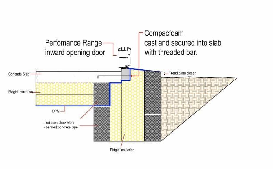
I can see that in the drawings it looks a bit like the opening part of the door is within a frame, including at the bottom, but that's not normally how side hung doors work - usually the outer frame is at the head & jambs but not at the bottom because you don't want a sill to trip over at the bottom (or to prevent level access). If I look at GBS's own doors brochure I can find the drawings attached below for example. Perhaps this detail was actually used with some kind of door that has a frame across the bottom. But even so ... that would make it more like a side hung window, and normally if you are fixing a side hung window much of the load is actually taken at the jambs. And of course you can effectively suspend a conventional window in line with cavity insulation using straps, because the load is mostly taken at the sides, and at the sill you don't have to support the main weight of the window, you mostly just have to close the cavity and fix a sill for drainage etc. That's why it's difficult to detail things like large sliding windows/doors, or bifolds, because they do rely on putting a lot of load onto the bottom frame. And the thermal detailing is very often compromised there, because the installers usually demand something very solid without risk of deflection. Sometimes in cavity walls (at ground floor at least) that ends up with the cavity simply being filled with concrete up to the threshold level. Or you end up placing the door in line with the inner blockwork, and you can put insulating blocks below it but you then have to fiddle with various steps in and out of the insulation line. I'm always looking for something that would be like a loadbearing cavity closer. Or even something like a kind of upside down version of a catnic lintel. Something designed to bridge the cavity and take a substantial load, without creating a thermal bridge. I don't see that compacfoam can do this job, but would be pleased to be proven wrong.
-
All that is being supported by the compacfoam there is an aluminium threshold strip, and foot traffic, as far as I can see. But this is what's frustrating about that detail - it's not linked back to any information about what it's actually doing, or how to know what it can or can't support.
-
I'd be happy to be proven wrong but I'd be very surprised if this material can be side-fixed, or span across a cavity, and then bear substantial loads. I've not found in their literature anything that suggests it can be used this way.
-
Let's say, conventional cavity wall buildup with rigid board insulation, suspended floor (either beam & block or timber) and I want to install a heavy sliding door system (which bears weight onto rollers at the bottom), but I want to try and install it in line with the cavity insulation (like you'd try and do with a normal window to ensure continuity of the insulation layer).
-
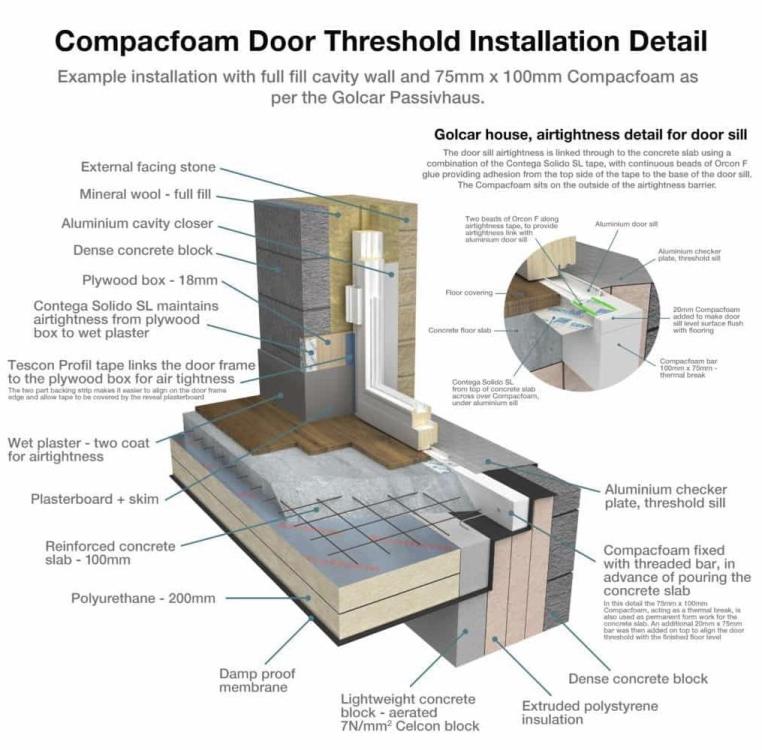
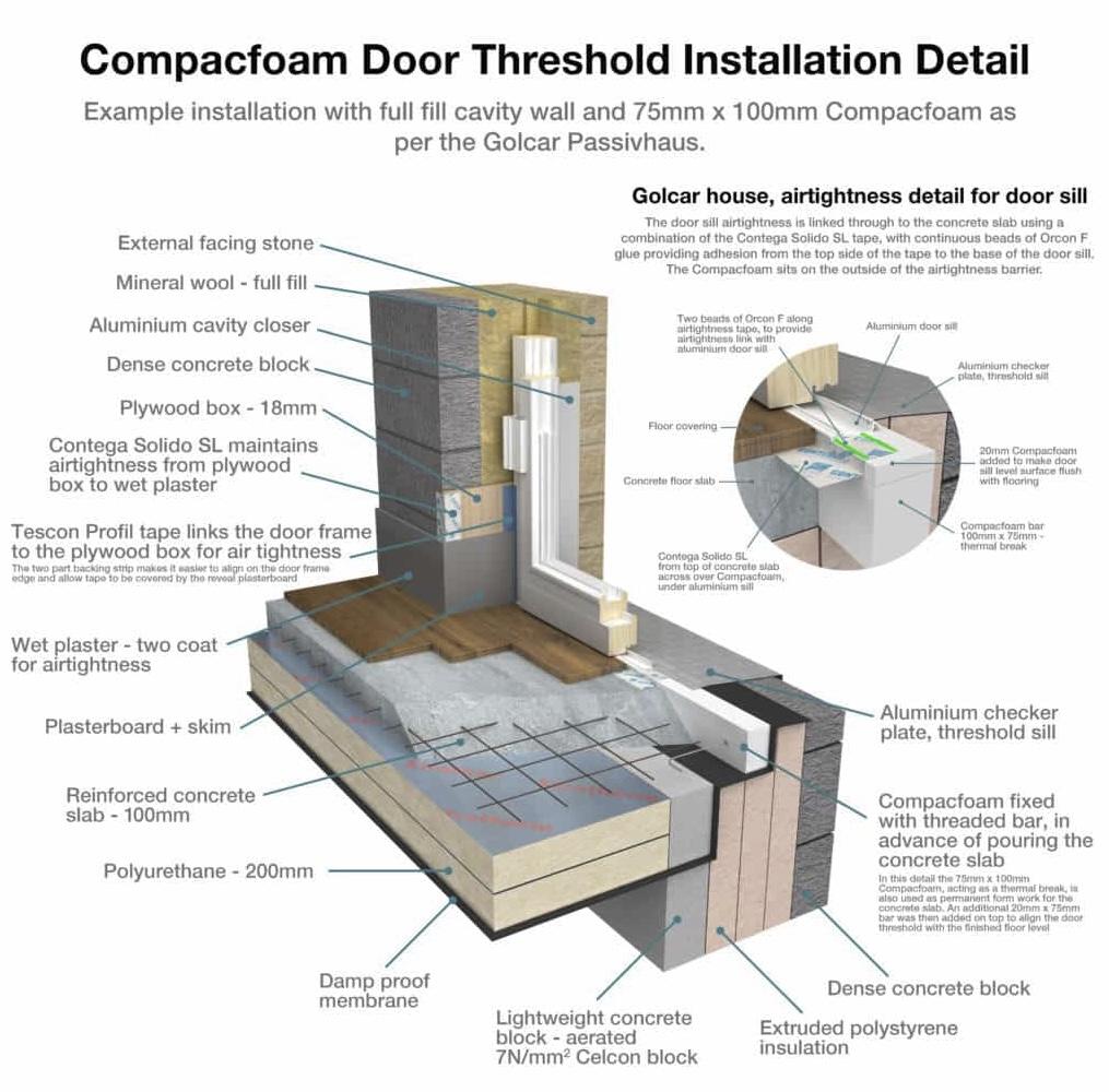
These images appear on the Compacfoam page in the Green Building Store. But this is not a detail that appears in Compacfoam's own literature and there seems to be little further explanation of the context, exactly what the compacfoam is doing or what types of situations it would be appropriate for. Is the Compacfoam strip supposed to be bearing any substantial load here? And if it is, does it rely on cantilevering out from the concrete slab? Is it relying on the extrude polystyrene below it and if so what's that supported on? What load does it need to bear anyway, seeing as all that is fixed into it is an aluminium threshold strip? Is it just the weight of foot traffic at the threshold - and if so, the "checkerplate" "tread plate closer" seems to be deemed enough to span across the XPS insulation already so why not just use that? Is it that the compacfoam is actually not doing anything other than replacing a bit of timber as formwork for the edge of the slab, and as something convenient to screw the threshold strip into? When I first saw this detail I thought it might be something I'm always looking for; a way of supporting the weight of a heavy door or window in line with the insulation layer in a cavity wall buildup - but that's not what's happening here, right?