


IanR
-
Posts
1857 -
Joined
-
Days Won
6
Everything posted by IanR
-

Volume of a complex shape: a bit of head scratching
IanR replied to ToughButterCup's topic in Foundations
Which you can import to Sketchup (Google Earth topology), but if it's a constant slope you should be able to estimate the average depth "fairly" accurately. -
Volume of a complex shape: a bit of head scratching
IanR replied to ToughButterCup's topic in Foundations
If I've read that right, it's estimating the area of the wedge you are struggling with, but estimating the average slop across the area you are OK with. If so use Google Maps. Switch to satellite view, right mouse click in one corner of the area and trace around the lopsided wedge shape. When you click back on to where you started it will give you the area (as well as the circumference). Then multiply this by the average depth. -
There're too many unknowns to make any real estimates, but you could take the Tue 18:00 to Wed 06:00 period where there is no heat gain from solar and see that, with an average temp differential of approx 2.5 degrees, your house dropped 0.2 degrees in 12 hours. Seems "pretty good", but anything more definitive with the unknowns would be a guess.
-
Insulating Steel Beams: how best?
IanR replied to ToughButterCup's topic in General Construction Issues
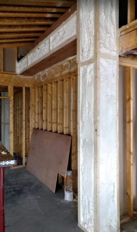
I appreciate this is resolved for RA, but another option for anyone searching for similar in the future: We have 4 Columns of the original cow-shed structure (holding up the roof) that drop into our thermal envelope, and I had to add additional goal-post bracing between each pair as I wanted to move the original racking braces to allow other areas to be opened up: We boxed these in with ply and then used a closed-cell spray-on PU foam, (Elastospray 1629/1 from BASF) to insulate, make airtight and stop and moisture getting to them: The foam needs to be 60mm thick to guarantee no moisture getting through, but we went thicker anyway to maintain the integrity of the thermal envelope.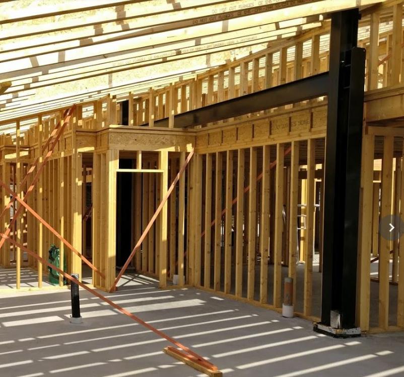
-
Sounds to me that it's going to be OK. Let the GeoTech company know the depth of the foundations and, if at that depth the bearing capacity is better than the 25kN/m2, ask them to either revise the max bearing capacity or add an addendum showing a higher bearing capacity at the proposed foundation depth. Your SE sounds like he's being awkward, but perhaps he feels he's done the job he was contracted to do. I wouldn't be surprised if the SE at LABC also knows that it's OK but doesn't feel he should have to infer that from the report, so wants it spelled out. To be fair, you've contracted different parties directly for the different roles, (which is the most "fun" way of doing it!), so you will end up being the interface to each of them and resolving the issues. Think of the money you are saving by not contracting a PM or Architect to look after this for you. And you'd probably still find yourself in the thick of it trying to resolve issues.
-
Just taking a step back, a bearing capacity of 25kN/m2 is very low. How is it specified in the soil report that this is the minimum. I assume some bore holes were dug and that's when the pressure test was done? was the 25kN/m2 perhaps just at a certain depth when a maybe a water seam was pushed through? This was my experience on my current site. 200 - 400kN/m2 in most areas and dropping sharply in one bore hole to 20 kN/m2 for a short distance at a particular depth. The Geotech company then wrote a report high lighting this a suggesting a risk that needed to be explored further with many more bore holes and included a quote for doing the extra work. We called them out on this, high lighting that this as a local anomaly at a depth that would not effect the foundation and they mumbled a bit giving a few excuses and then re-wrote their report with a minimum 200 kN/m2 bearing capacity. If the bearing capacity really is 25 kN/m2 for the whole site then in my limited experience I would have thought piling would be the only option. In which case start to get formal with your SE, as per PeterW's suggestion. Edit: crossed with Daedalus
-
OK, back to the OP: Answer: Yes there is, the free acrobat reader application that's installed on the majority of PCs and laptops. All discussion beyond this regarding level of accuracy is due to an incorrect assertion that PDFs cannot be relied upon, I'm not suggesting that the level of accuracy achievable is required by the builder on site. That dimension measures 5003mm on the built frame, all openings are within a few mm of their design size . Touchwood have a pretty good process for hitting the opening sizes "spot on". But I understand your point if it were a masonry build.
-
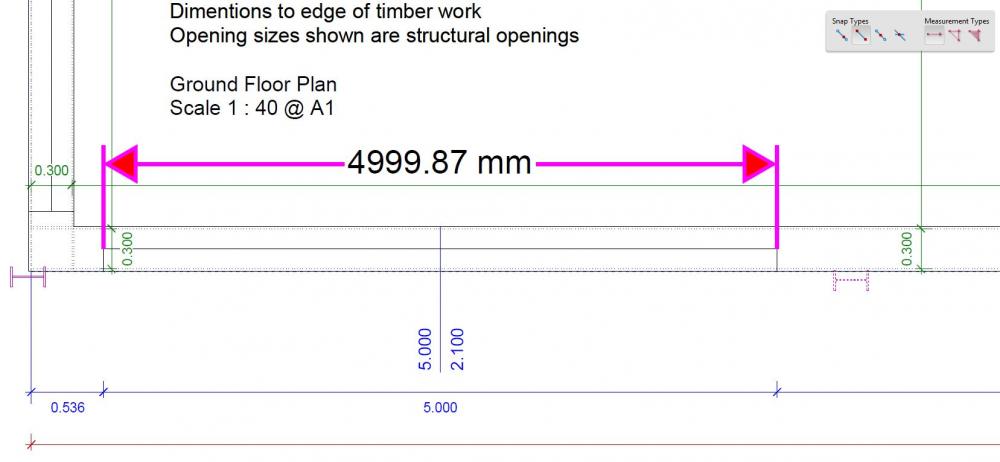
That's not evidenced by your opinion on the capabilities of printing to PDF. @TerryE with all due respect, that's a poorly "printed", PDF and if it were part of the delivery for a paid-for Service I would have refused it. It looks like the result of a "PrtScn". @PeterW The quote of mine you have used is attempting to say that the accuracy of "within 1mm" that I'm suggesting is of the true 1:1 length. Here's one I did not do earlier. This is the corner of the GA drawing for my frame. It's received directly from the Frame designers and I've just opened it up, selected measure and set the 1:40 drawing scale: The opening I've measured using the free Acrobat Reader application is 5000mm wide, as shown by the CAD dimensions, the dimension that the measure tool puts on the drawing is the one that reads 4999.87mm So, accurate to 0.13mm in 5000mm on an A1 formatted drawing that is drawn at a 1:40 scale. I'm zoomed in to 200% to take the measurement. Any fuzziness of the image is due to JPeg compression. There is nothing special about the PDF, it's printed in colour at the correct A1 Size and is 121Kb filesize. I could have picked any of the drawings I have received from the frame designers, or the original Architect that helped with the Design & Appearance Condition, or the Architect I used for some "Passive House" detailing work or the drainage guy that specified the land drains, or even any of my own. CAD Authoring, digital collaboration and digital archiving got its act together years ago to ensure that when the paper-less society does eventually arrive, original drawings archived in digital format can be relied upon to not require legacy CAD systems to remain functioning in order to interpret a drawing. Adobe are at the fore-front of this for 2D data and are pushing hard to do the same for 3D.
-
Well, I can vouch for CutePDF, although I generally use the Acrobat drivers. It's probably worth you getting familiar with the print options, you may be more successful with your printing.
-
Are you suggesting that there is CAD software that is not able to print to scale? While errors can occur, as Ferdinand points out, with physically printing on to paper, not such errors occur when the file is electronically printed to PDF, as long as the Architect knows the basics.
-
That's not what I'm saying Say a Ground Floor Plan at 50:1, correctly printed to PDF, will be able to be measured, within Acrobat Reader, to within 1mm of its Full Scale dimension.
-
PDFs printed from CAD by a competent Architect or Technician will be scalable to an accuracy of less than a millimeter. It's pretty basic stuff, if they're not capable of achieving a to-scale PDF I wouldn't trust them with much. PDFs created from scans are of course a completely different matter, just as photo copies of a drawing would be.
-
The free acrobat reader from Adobe has a measure option under analyse. You just need to select it then right mouse click and set the scale to what the drawing is.
-
If it was 145 SIPs on its own then it was probably a large wood burner as the SIPs will just have met building regs. I'm not sure of the benefit of SIPs for the open plan and vaulted ceilings. With large spans the required increase in timber fraction and cold bridging will drop the "real" performance of a SIP structure. With an I-Joist roof you just go for a deeper I-Joist for the large spans, no negative effect on performance. You may not be comparing like-for-like on your quotes. It's unfair on MBC to compare their twin-stud costs to a 145mm SIP cost. You need to add another 95mm of EWI to the SIP price plus a whole load of air tight detailing. When I costed SIPS and twin-stud, for the same performance the price was equivalent, I-Joist was a little cheaper.
-
What U Value are you targeting? While foamglass is better insulating than other block work, it's not quite as good as EPS, so to achieve a Passive-slab type level of 0.1 U value for the floor and perimeter you'd need roughly 350mm foamglass. But that's not the whole "issue" with SIPs. If you wish to eliminate cold bridging and condensation risk on the sole plate then you need an additional external layer of insulation that drops down passed the sole plate. Where as on a thicker twin-stud wall or I-Joist wall there is an opportunity to place an EPS upstand under the middle of the sole plate so that the inner face of the wall is over the warm floor and the outer face is over a cold ring beam (or on the EPS upstand itself in the case of the twin-stud) and therefore braking the cold bridge, you can't do this with a SIP panel. Hence the need for EWI to isolate the sole plate from the cold side. My experience is that SIP suppliers are much happier about additional insulation going on the inside than the outside, but I believe quite recently Kingspan have started to support EWI on their panels. It's worth looking into the Potton PassivHaus that used Kingspan SIPs, their foundation was very complicated to resolve the cold bridging issues and IIRC they specified EWI to cover down passed the sole plate. Seems to me there are easier solutions with twin-stud and I-Joist walls. Plus you get to use an insulation with better decrement delay and acoustic properties.
-
Wet room without mosaic tiles?
IanR replied to divorcingjack's topic in Bathrooms, Ensuites & Wetrooms
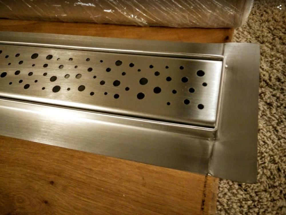
Mine aren't in yet, but hopefully will be in the next week or so, I got my linear gullies from a polish manufacturer for +/- 150 EUR (depending on length), Delivery took a week. http://www.kratkisci...w-wody,641.html They're relatively good quality, with an integral stainless steel trap and vertical, Dia 50mm, drain connection: Mine are going into a passive slab. I've run 110mm pipe vertically up through the EPS and have terminated this with a 110 to 50mm offset adapter. It's difficult to get the drainage pipe perfectly accurately positioned without any walls up so the offset adapter allows the position to be fine tuned to where you need it. We had hoped to put formers in for the leave gaps for the sloping floors, before the concrete pour but the ground workers ran out of time so ended up cutting the floors in after which was a lot of work. We're not using a tray but will put a local screed in to accurately get a 1.5 degree slope on the floor and get the linear gullies correctly positioned, and will then fully tank the whole area before tiling. There was a big ol' discussion on different options on eBuild, but unfortunately the pictures aren't accessible any longer. http://www.ebuild.co.uk/topic/16356-wetroom-or-shower-tray/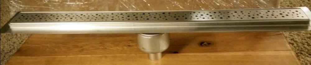
-
Is it a standard build up including the Kingspan K12? This seems to go against the advice from Knauf. From Knauf's timber frame document: Bold format added by me Since the K12 is vapour impermeable, it does not follow this guidance. Might be worth taking advantage of the offer of condensation risk analysis. I have a Touchwood frame, and their standard build up is (inside-to-out): Foil backed plasterboard (VCL) 300mm/350mm JJ I-Joist with Warmcel Eggers DHF Fibreboard (Airtight layer) Breather membrane
-
German Speaking WC expert required please
IanR replied to Fallingditch's topic in Bathrooms, Ensuites & Wetrooms
Here's a good reference http://www.users.waitrose.com/~ttagrevatt/vlav/works_pans.html -
German Speaking WC expert required please
IanR replied to Fallingditch's topic in Bathrooms, Ensuites & Wetrooms
From what I could gather, washout-down (better?) flushes contents out the bottom of the pan with greater force and up and over the u-bend, the wash-out (more likely to get blocked??) has a shallower pan and the force of the wash has to push the contents up of the edge of the shallow pan before it goes down through the u-bend, The other is rimless. I guess this is an aesthetic difference that requires better control/direction of the flush water to not splash over the edge as it doesn't have an upside down U channel around the upper edge to control the path of the water. Reuter.de has an English language option on the website and similar pricing. -
MVHR Ducts and compatibility with Units
IanR replied to Dudda's topic in Mechanical Ventilation with Heat Recovery (MVHR)
If you've not looked at Airflow, I'm going with a small commercial unit, the DV1100, which is PH Certified, F7 filters etc. My internal volume is around 1650 m3, so I was otherwise looking at 2 residential units. Airflow will do you a free system design, Bill Of Materials, and target price for you to then take round to their distributors to get the best price. -
I'm hoping to use sun position to define slat angle, and temp to decide if they are needed at all.
-
Where does the light "leak" through? I knew those with wire guide can let the light through the holes for the wires, but I was hoping the tracked version, with edges tucked behind the cladding, would give pretty good coverage. I'm assuming yours is connected up to your Loxone. That's the way I'm going.
-
I'm going with Hunter Douglas external venetian blinds that will be tucked behind the timber cladding. For a 2.1m drop you need about 220mm above the window to retract them and they need a head box 120mm deep (for an 80mm slat), they have guides on the sides, either an extruded channel or wire. When we first quoted HD installed as well as supplied, but when I've gone back to order they no longer install so I've been passed to one of their "partners" to requote.
-
I have the same concern. Dritherm is vapour permeable, but the K12 is not, so your OSB is in trouble. Even with a vapour check layer on the inside (foil backed plasterboard???) I would have thought you should still have reducing vapour resistance to the outside if you have a vapour permeable main insulation.
-
That seems really efficient to me, and much quicker than I would have expected. How granular have you gone with your fabric model? Do you have approximate U Values for walls and roof or have you modelled all potential cold bridge areas ie. extra structure around windows, doors, eaves and true timber fraction etc. I'm sure it's a case of diminishing returns (to accuracy), and no idea at what point the critical mass of detail is achieved. In my case I wasn't willing to reduce glazing to a sufficient level so have used automated external blinds to bring the overheating risk into the excellent range. In PH Certification context, I don't believe that means it has been designed out, whereas if I had used fixed brise soleil it would have done.




