
Fallingditch
-
Posts
217 -
Joined
-
Last visited
-
Days Won
1
Recent Profile Visitors
3525 profile views


Fallingditch's Achievements
Regular Member (4/5)
57
Reputation
-
There are several suppliers of 'integrated bedroom furniture'. In additional to IKEA and DIY Homefit are supplyonlybedrooms.co.uk, kitchenbedroomdesign, larkandlarks, and onlinebedrooms. Trustpilot scores vary quite a bit. Assembly instructions are few and far between: "designed for installation by professional tradesmen" - however onlinebedrooms have published a useful set of online videos on youtube.
-
 3 mm
3 mm -
Yes, glue direct to SLC
-
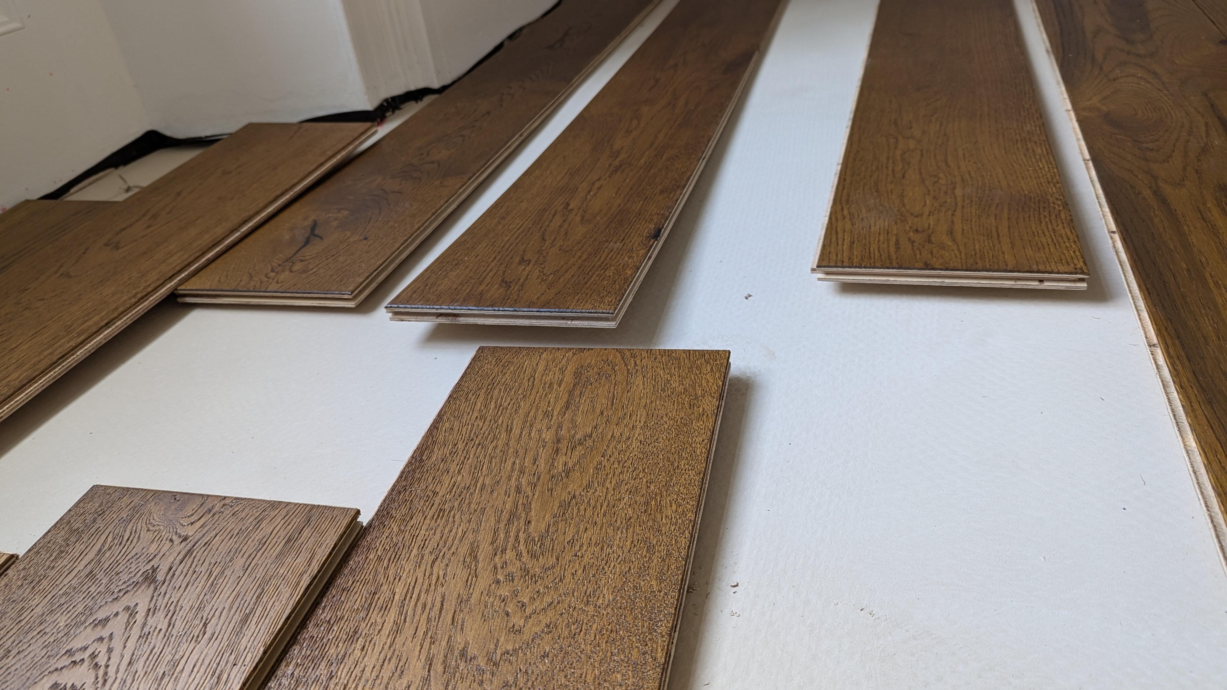
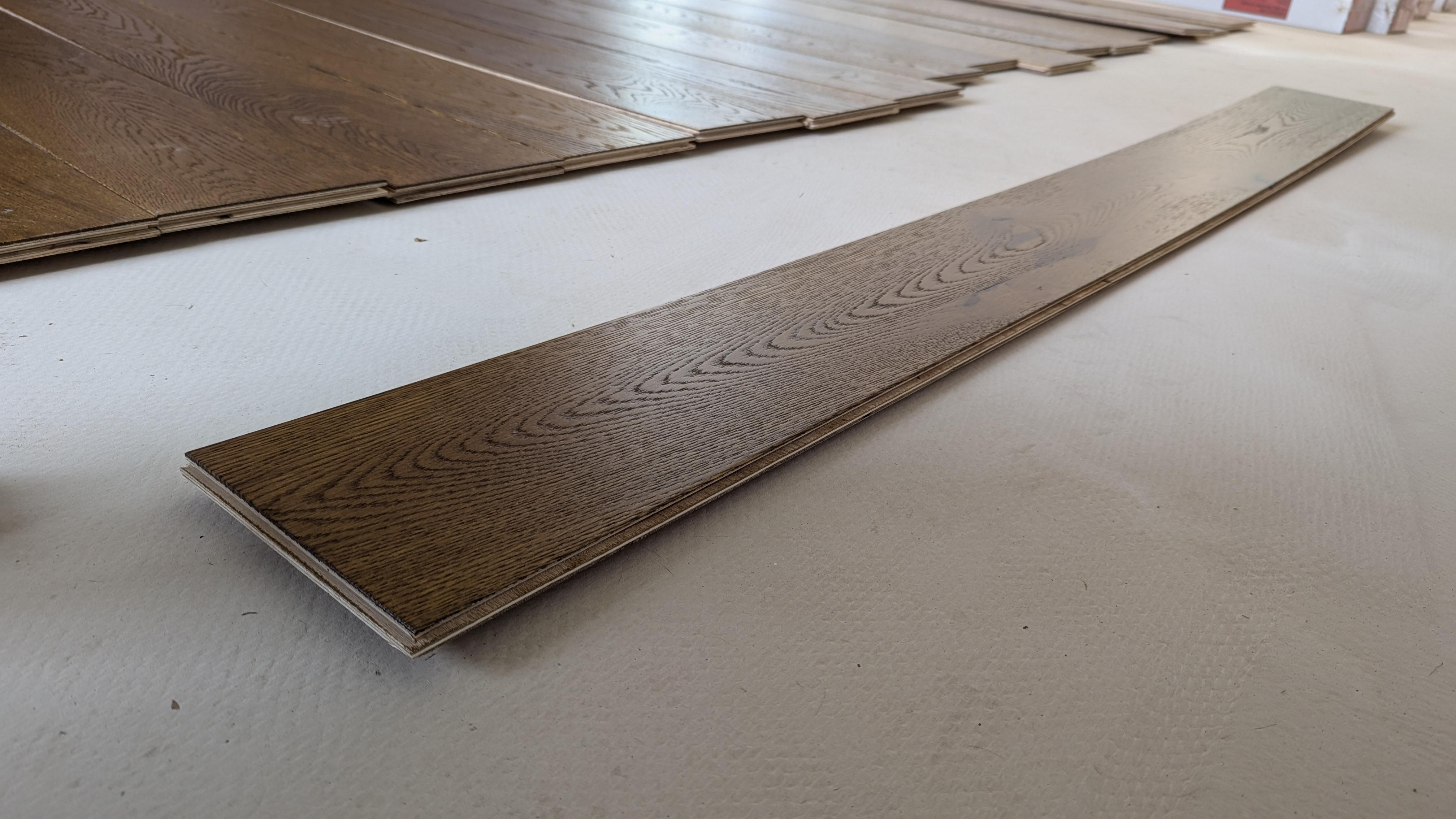
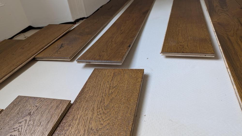
Just bought 30 sq m of T&G engineered Oak flooring. The second sentence on the Installation Guidelines sheet inside the box states "Your Emerald 14mm T&G Engineered Flooring does not require a period of acclimatisation however warranty conditions dictate that the engineered wood flooring is to remain in the sealed packaging prior to the date of installation". So we unwrapped four boxes Friday night, and by Sunday morning, many of the planks had bowed - one of the images below shows a 1850 x 190 plank bowed by 8mm at one end and 22mm at the other end. (Its sitting on a SLC floor which was poured a week ago. RH in the room is 75 %; house is in Cornwall and RH is seldom below 75% ...) The Installation Guidelines sheet also states "at the time of installation and thereafter, conditions should be within the range expected when the building is in use. The RH of the air should be between 45 deg and 65 deg" ..."These figures also apply once the floor is installed" ... "The installer/owner assume all responsibility for the final inspection of both the site suitability and product quality prior to installation in order that the requirements of these instructions are fully complied with. Claims of any nature will not be accpeted if a fault is visibly noticeable prior to installation". I do not have a good feeling about this situation. Thoughts?

-
Stainless Steel Slate Hooks or Copper Slate Nails?
Fallingditch replied to JamieK's topic in Roofing, Tiling & Slating
comment: "I have used over 30,000 slate hooks. Not one slate has come off." Newcastle college demonstrates the differences between nailing and hook fastening -
Quality and stylish switches - Trendi not doing it
Fallingditch replied to jamiehamy's topic in Lighting
Just in case anybody wants to buy Niko light switches post Brexit, Electro Colli will ship Niko electrical components to the UK, including Niko Home Control (Home Automation). (DMLights have ceased supplying Niko). FYI I just ordered about £120.00 worth of switches - took about a week from Belgium and no customs duties or additional VAT payable. -
I need to fit a bank of four switches to control pendant lights and sconces in our refurbished kitchen diner. I was going to mount the switches on a stone partition wall but a slight measuring error with kitchen units means that I no longer have space. I therefore want to mount them on the tongue and groove end panel of the oven unit. I wanted to check whether this would be compliant with Building Regulations. The Pro Certs Software Blog states: Local Isolation for Kitchen Appliances - Kitchen Socket Positions - Pro Certs Software “The IEE Electricians Guide to the Building Regulations, 5.2.2 Locations of accessories in kitchens state: (i) Wiring accessories (e.g. socket-outlets, switches) should be mounted on the building fabric and NOT on kitchen furniture. BUT “in many cases most modern integral appliances such as a built-in dishwasher do not have enough space behind the appliance to fit a plug and socket-outlet, which is when an electrician may decide to install the socket in an adjacent cupboard … Electrical safety first answers this question: Can accessories and electrical equipment such as socket-outlets and under cabinet lighting be fixed to kitchen units? “Yes, provided that they are securely fixed to rigid parts of the units that are not demountable or otherwise liable to be disturbed in normal service. However, care must be taken to comply with all the relevant requirements of BS 7671, including accessibility for inspection, testing and maintenance, and provision of adequate protection against damage (by impact or water for example) for the accessories, equipment and associated wiring. Regulation number(s): 530.4.2 Regulation 530.4.2 of the 18th edition of the BS 7671 wiring regulations is about the mounting of unenclosed equipment, such as switches, sockets, and terminals. It states that “unenclosed equipment shall be mounted in a suitable mounting box or enclosure in compliance with the relevant part of BS EN 60670, BS EN 62208 or other relevant standards such as BS EN 61439 series.” This is to ensure that the equipment is protected from mechanical damage, moisture, dust, and other environmental factors that may affect its performance or safety.” So, it seems that lightswitches can be installed on kitchen unit end panels, but they must be housed in mounting boxes compliant with (eg) BS EN 60670. But aren't most moulded surface mounted boxes compliant with BS EN 60670? Seems like I can just go ahead and do this irrespective of the Electricians Guide saying "switches shouldnt be mounted on kitchen furniture"?
-
What was the outcome please @ValleyBoy1958? Did you get it working OK?
-
Just outside of Callington. We've moved into the barn as well.
-
Thanks for all the excellent advice. Apologies for not replying sooner - have been away. I should have been clearer about a couple of things: - there is no heat pump supplying the system, just a 28kw Vaillant combi (propane) boiler which feeds the radiator circuit (at say 75 C) and will feed the new ufh circuit (thermostatic valve controlled down to say 25 degrees. - the pair of T3 convector radiators (which I have already bought) were chosen to be as unobtrusive as possible whilst able to emit significant heat (1.1 kW AT50). They will be manually controlled with standard TRVs - the existing (old) circuit is copper, partly 22 mm and partly 15 mm. No manifold. If I T'd off the 15mm there would be an 8m run; off the 22mm there would be a 14m run. So seems to me the key points are: If the point of these T3 convector radiators is to occasionally get a belt of heat quickly into the room, it's less risk to supply each radiator individually with 15mm F&R? and chasing the pipes into the wall does have advantages (for the same reasons as wall hung toilets) - so maybe I should drop the idea of casting them into the slab after all? and they really must be insulated where they run down the channel in the wall? and I might as well run them back to the 22mm (for an extra 20 m of hep2o)? Many thanks to all for your comments 😊
-
That would be a good idea. They were discussed in the Plastic vs Copper thread, but I didnt see any images of what their final appearnce is ... how do they compare to (eg) sheathed 15mm plastic? (The room has an original victorian panelled bay window, so I am planning on installing two 600 x 400 x 160 T3 ultraheat convector radiators either side of the bay, so they are as unobtrusive as possible. Getting neat F&R pipes rising to them is also pretty important).
-
Victorian stone house renovation. Existing CH system with distribution in the ground floor ceiling void: 15mm copper pipes dropped down feeding 4 radiators on the ground floor. We have dug up the existing concrete and laid 150mm PIR insulation. We are about to pin the Pert al Pert UFH pipes to the insulation and then cast a 100mm concrete slab in a couple of weeks. So we will be having two independently controlled circuits: new UFH on the ground floor, but retaining existing radiators on the first floor. However, we will be retaining/installing a matched pair of small T3 convector radiators on the ground floor at the far end of the house. Most of the time they will be manually switched off, but on cold days when the UFH turns out to be insufficient (the house is poorly insulated), we will manually turn on the radiators to top up the temperature in the room. (Small matched pair for aesthetic reasons). So here's the question. Again for aesthetic reasons, I want to bring the 15 mm plastic flow and return pipes down from the ceiling behind the plasterboard, and then run them 3m through the slab (and away from the UFH pipes) to the new radiator, so no pipes or boxing will be seen. I will be letting the slab dry out for 4-6 months before turning on the system. I can't find any advice as to the risk of running a short length of central heating pipes through a concrete slab? Do people do this? Is it risky? What sort of pipe is best to lay? Should I lay them in conduit? It's such a short run, and the radiator will be used only sporadically, that I don't think there’s any point insulating the pipes.
-
any idea where to source longer (say 8m) 10k NTC sensors please?
-
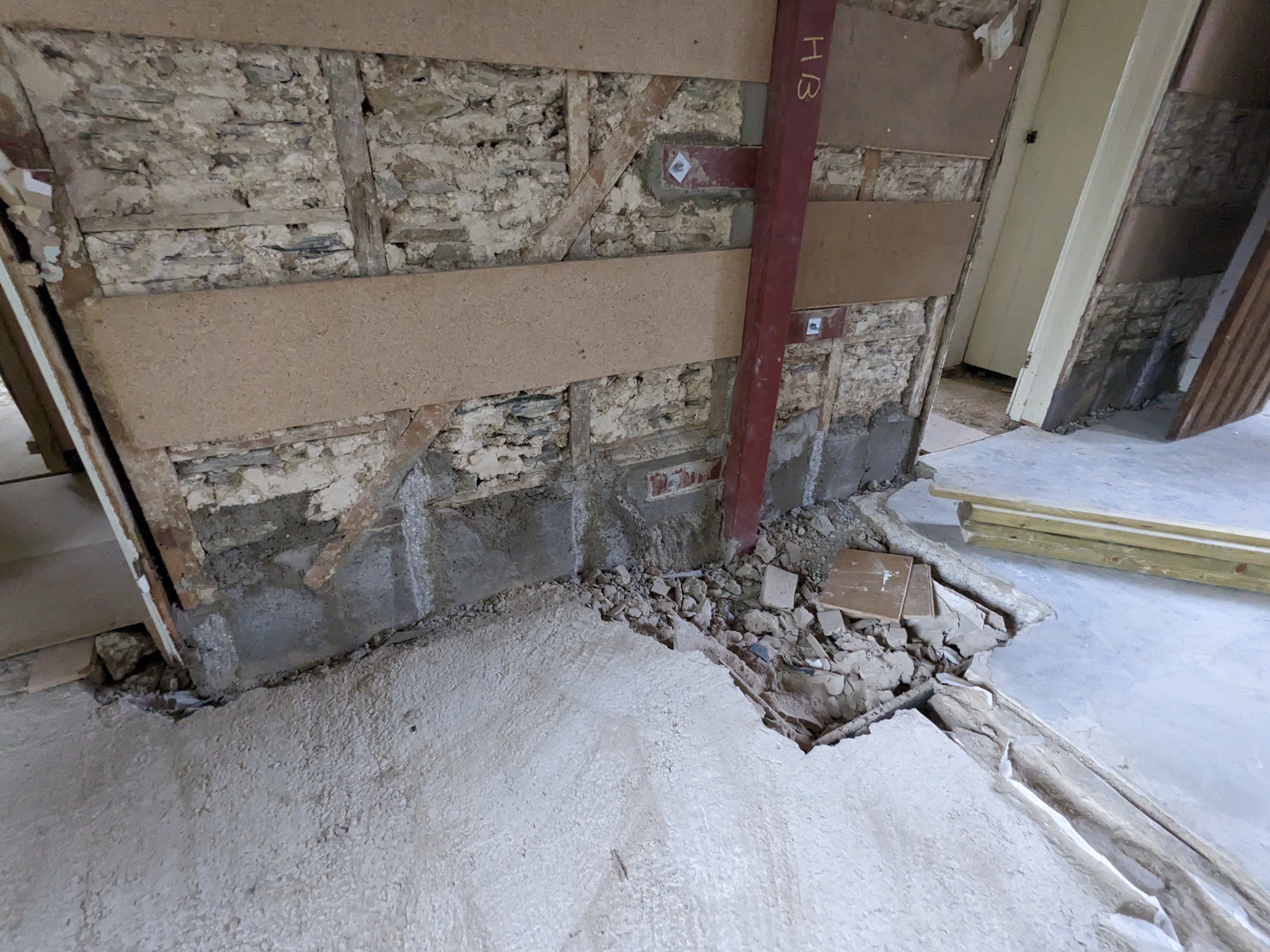
In fact, what we did was to cut away the rotten section, screw in a stud, put a temporary shutter around it and then and then cast a new concrete 'foot' to support it - seems like a good solution to me.

-
Boarding over definitely (or retaining existing lime plaster and making good).