IanR
-
Posts
1842 -
Joined
-
Days Won
6
Everything posted by IanR
-

Cheap, Thermally Efficient Non-Structural Wall Detail
IanR replied to Nick's topic in General Construction Issues
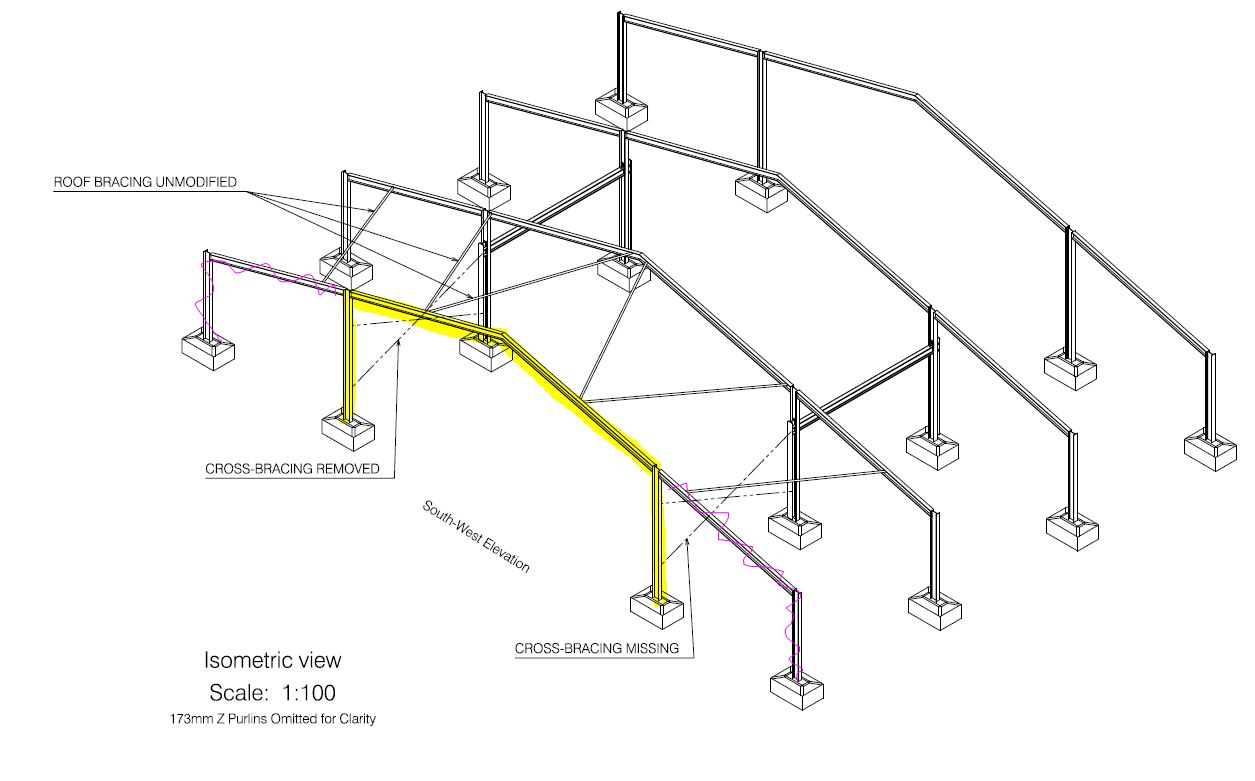
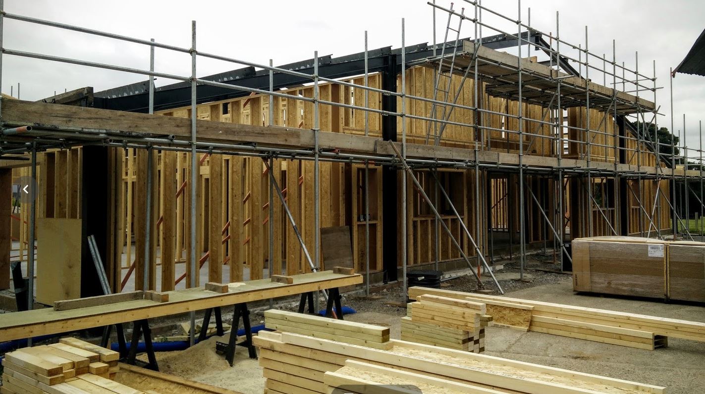
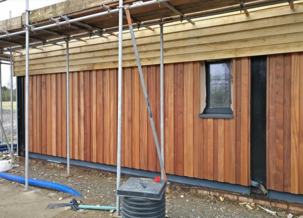
A 12m span is easily achievable in the typical steel sizing used for Agricultural barns, without stepping up to the monsters used these days in warehouses and distribution centres. The sketch below was for the structural changes I made to the primary frame of my barn. The high lighted yellow portion is the main barn span and is what your are describing and the areas crossed out on the first portal are lean-to bays that are add-ons. The distance between the two high-lighted vertical columns is 45 feet (13.7m). The width of each bay 19'6" (6m). Ridge height around 6.5m. Columns are 10" x 5.75" and the roof portals are 8" x 5.25". Not shown are the 173mm Z Purlins and 9" x 3" Eaves Beam timbers similar to what you describe. Typically the first bay is braced as shown and the follow on bays lean against the braced one. I removed the low level cross-bracing (simple 2" tube) as it got in the way of an open area I wanted and had to replace it with the giant goal-post arrangement you can see between the internal columns of the centre bay. As I said previously, the portal frame structure is designed for a light-weight roof, ie. profiled sheet steel, corrugated cement board or insulated profiled panels. I'm not sure it will hold up the weight of structure required for a domestic warm roof that you'll be after in your double volume area. I'm not sure how much this image shows: The steels are half in - half out the external wall. The sheathing on the timber structure actually notches around the steels so the wall narrows across the width of the steel. And then when the cladding does its bit, the lower portion of the steels are visible and the upper covered, as per planning requirement. I know I sound like a broken record, but in your shoes I'd do it with a large glulam ridge beam and I-Joist roof structure. I'd hate to add up what it's cost me to integrate the steel frame. But I had no choice, my planning is for a conversion, not a new build.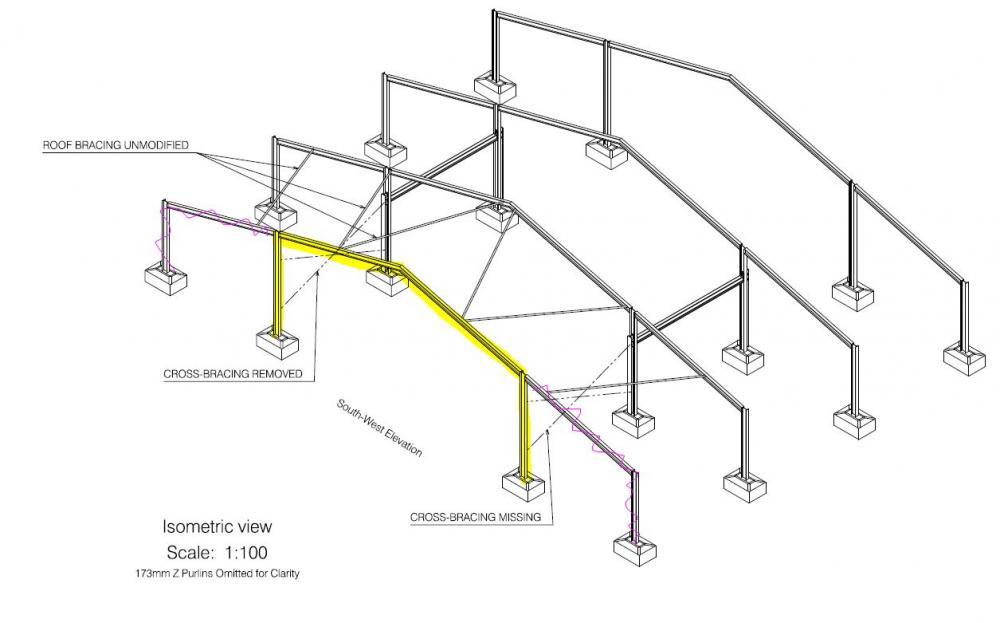

-
Cheap, Thermally Efficient Non-Structural Wall Detail
IanR replied to Nick's topic in General Construction Issues
Ah, this is two storeys Are you expecting a completely open ground floor, with no internal columns? You'll need a Structural Engineer to work out the most economic way of achieving that if you do. If I've understood your orientation correctly I see you needing an 8m steel at first floor (running parallel with the ridge) that will require structural gable end walls for it to sit on. Maybe you need to work up a section. While you are thinking your timber walls will take the wind loading, where are they transmitting those loads to. Do you plan to structurally tie them into the steel frame at the eaves and first floor? Personally I'd start by trying to do it in timber, with steels to reinforce if a timber member gets too big. Having had to work around a steel portal frame I'd certainly try and avoid it in the future. Ridge height is very difficult to control across each of the portals. The wider the span and shallower the pitch the height variance is increasingly sensitive to the length tolerance of the beams and weight on the roof. I assume you'll need 3 portal frames to make up 2 x 5m bays, there's a risk of the ridge not being visibly straight. This goes unnoticed on agricultural buildings, but probably not on a house. Portal frames are also designed for a light-weight roof covering, what did you have in mind? For mine the steels are outside of the thermal envelope. Due to a planning caveat they have to be externally visible in some areas, so also outside the cladding, but covered in others, so behind the cladding. [But: I do have 4 steel columns that are internal to my floor plan, helping hold up the roof, but due to how they are boxed and insulated they technically remains outside the thermal and airtight envelopes] When I mentioned the DHF board that was for the structural timber frame scenario and no steel portal frame. I found it was relatively easy to develop a hybrid (timber and steel) structure where timber walls, inline with and attached to the steel columns, where capable of supplying the racking support to the portal frame and the portal frame capable of dissipating the wind loads on the timber walls. But, if you've got that amount of structural connection between the two how do you then thermally isolate them and stop vapour getting to the steels, unless you can wrap the whole structure with external insulation, leaving just the floor connections to resolve. -
Cheap, Thermally Efficient Non-Structural Wall Detail
IanR replied to Nick's topic in General Construction Issues
Not sure where you are in the country, but I had very good Service from John Payne Insulation in Norfolk. They travelled to me in Essex, but I got the feeling they wouldn't like to travel much further. Very approximately, expect to pay £25 / m2 of wall/roof area for installed blown cellulose fibre at 300mm/350mm thick.. Warmcell costs have gone up since manufacturing went abroad (I think Warmcel was bought out???). I know JPI are looking at and trialling alternative brands to reduce costs. -
Cheap, Thermally Efficient Non-Structural Wall Detail
IanR replied to Nick's topic in General Construction Issues
Just taking a step back... The title of this thread is "Cheap, Thermally Efficient Non-Structural Wall Detail", however what you are developing here is a structural wall. Have you talked yourself out of the steel portal frame à la "BarnHaus"? or is this still your current direction. If you are still considering the steel portal frame then you could consider a less structural options than the I-Joists to make of the external walls. At the moment there is a double-count in your strategy ie. both the steel columns (suitably braced) of your portal frame and your I-Joists of your wall detail are independently capable of holding up the roof. My current build is a conversion of a steel portal framed cow-shed and in the early days I enlisted some help from Dr. Ed Green to develop early concepts on integrating the portal frame, due to his involvement with Barnhaus. I wasn't interested in the straw bale insulation, so we looked at several other options. and always the plan was to keep the steel outside the thermal envelope and ensure no warm moisture could get to it. Integrating the steel structure into the timber frame structure adds an extra layer of difficulty. The portals of the the steel frame will require racking bracing at wall level (as well as the roof) and as you have drawn it the racking braces will run through the I-Joists. It would be much easier if the steel columns were external to the wall, but this looses you some floor space you are trying to retain. Mine are half in, half out - a compromise that adds complexity. Your choice of steel portal frame is due to room size. What's the roof, ie. pitched of flat, and what way does it run. It's quite possible you could do this with Glulam and I-Joist to avoid the Steel Portal frame, and simplify your structure. With regards to your I-Joist wall detail, and to play devil's advocate, if cost and wall thickness are critical then there's no need for a service void if you are only running suitably sized cables in the external walls. But you shouldn't run plumbing. Also, your VCL could be achieved with a foil-backed plasterboard if your wall build up is so designed. Also, your outer sheathing could be both racking support and the airtight layer with something like Egger DHF board, avoiding the need for any airtight or VCL membrane. Designed right, its a cost effective solution. -
Getting large bits of glass up onto a roof
IanR replied to thomas's topic in Skylights & Roof Windows
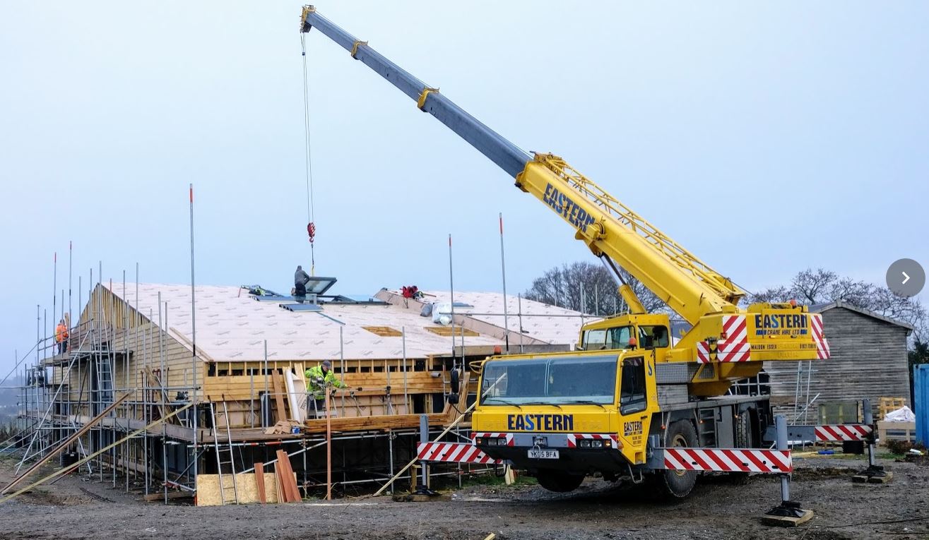
Do you need to lower it into position once on the roof? If so I think you'll need a crane and vacuum lifter: https://www.coppard.co.uk/pages/cranes/valla-20e.php [I have no experience of this company] The company I used only had bigger toys:
-
My stick frame was purchased as part of a design, supply and erect package with an air tightness guarantee. I'm not able to erect myself so I needed to pay someone to do it and I feel the 20 years of experience with the system the company I used has benefited the built frame and I hope the air tightness (not measured yet). If however I could have erected the frame myself and I was "just" after very good air tightness rather than "best in class" as well as a cold-bridge free design, then I would look to Cullen Timber Design Ltd. to design and sign-off the frame. If needed they can send cutting lists direct to joist/beam supplier and provide a very detailed drawing pack. What I mean by the air tightness comment is that the frame design inherently has good, robust air tightness detailing that I feel would deliver a very good result, but the experience of the install team lifts it to a level probably not achievable by someone new to the product. CTD did the frame design part for my package and it was a very good experience working with them develop the frame for my rather complicated site.
-
Does it have to be a plate of a certain size? Could you use a plate of 1/2 or 1/4 the area and therefore use 1/2 or 1/4 the load?
-
Yes, because it only has to get to xKg or xkN at the plate, not the entire axle weight, so doesn't need to lift the back of the vehicle entirely off the ground. ie. some of the weight is still taken by the suspension/wheels
-
I edited my note just as you posted this
-
Nope, it will just require the jack to lift further until the entire axle weight is taken by the plate (and the suspension is at full extension and tires lift off ground) Edited to add: If you're jacking under the Axle and not the Chassis, then it makes no difference to what you are calling the Unsprung scenario
-
Volume of a complex shape: a bit of head scratching
IanR replied to ToughButterCup's topic in Foundations
Which you can import to Sketchup (Google Earth topology), but if it's a constant slope you should be able to estimate the average depth "fairly" accurately. -
Volume of a complex shape: a bit of head scratching
IanR replied to ToughButterCup's topic in Foundations
If I've read that right, it's estimating the area of the wedge you are struggling with, but estimating the average slop across the area you are OK with. If so use Google Maps. Switch to satellite view, right mouse click in one corner of the area and trace around the lopsided wedge shape. When you click back on to where you started it will give you the area (as well as the circumference). Then multiply this by the average depth. -
There're too many unknowns to make any real estimates, but you could take the Tue 18:00 to Wed 06:00 period where there is no heat gain from solar and see that, with an average temp differential of approx 2.5 degrees, your house dropped 0.2 degrees in 12 hours. Seems "pretty good", but anything more definitive with the unknowns would be a guess.
-
Insulating Steel Beams: how best?
IanR replied to ToughButterCup's topic in General Construction Issues
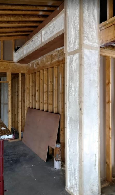
I appreciate this is resolved for RA, but another option for anyone searching for similar in the future: We have 4 Columns of the original cow-shed structure (holding up the roof) that drop into our thermal envelope, and I had to add additional goal-post bracing between each pair as I wanted to move the original racking braces to allow other areas to be opened up: We boxed these in with ply and then used a closed-cell spray-on PU foam, (Elastospray 1629/1 from BASF) to insulate, make airtight and stop and moisture getting to them: The foam needs to be 60mm thick to guarantee no moisture getting through, but we went thicker anyway to maintain the integrity of the thermal envelope.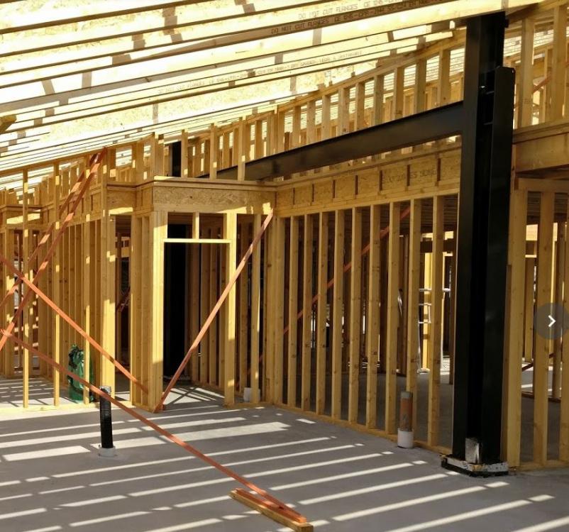
-
Sounds to me that it's going to be OK. Let the GeoTech company know the depth of the foundations and, if at that depth the bearing capacity is better than the 25kN/m2, ask them to either revise the max bearing capacity or add an addendum showing a higher bearing capacity at the proposed foundation depth. Your SE sounds like he's being awkward, but perhaps he feels he's done the job he was contracted to do. I wouldn't be surprised if the SE at LABC also knows that it's OK but doesn't feel he should have to infer that from the report, so wants it spelled out. To be fair, you've contracted different parties directly for the different roles, (which is the most "fun" way of doing it!), so you will end up being the interface to each of them and resolving the issues. Think of the money you are saving by not contracting a PM or Architect to look after this for you. And you'd probably still find yourself in the thick of it trying to resolve issues.
-
Just taking a step back, a bearing capacity of 25kN/m2 is very low. How is it specified in the soil report that this is the minimum. I assume some bore holes were dug and that's when the pressure test was done? was the 25kN/m2 perhaps just at a certain depth when a maybe a water seam was pushed through? This was my experience on my current site. 200 - 400kN/m2 in most areas and dropping sharply in one bore hole to 20 kN/m2 for a short distance at a particular depth. The Geotech company then wrote a report high lighting this a suggesting a risk that needed to be explored further with many more bore holes and included a quote for doing the extra work. We called them out on this, high lighting that this as a local anomaly at a depth that would not effect the foundation and they mumbled a bit giving a few excuses and then re-wrote their report with a minimum 200 kN/m2 bearing capacity. If the bearing capacity really is 25 kN/m2 for the whole site then in my limited experience I would have thought piling would be the only option. In which case start to get formal with your SE, as per PeterW's suggestion. Edit: crossed with Daedalus
-
OK, back to the OP: Answer: Yes there is, the free acrobat reader application that's installed on the majority of PCs and laptops. All discussion beyond this regarding level of accuracy is due to an incorrect assertion that PDFs cannot be relied upon, I'm not suggesting that the level of accuracy achievable is required by the builder on site. That dimension measures 5003mm on the built frame, all openings are within a few mm of their design size . Touchwood have a pretty good process for hitting the opening sizes "spot on". But I understand your point if it were a masonry build.
-
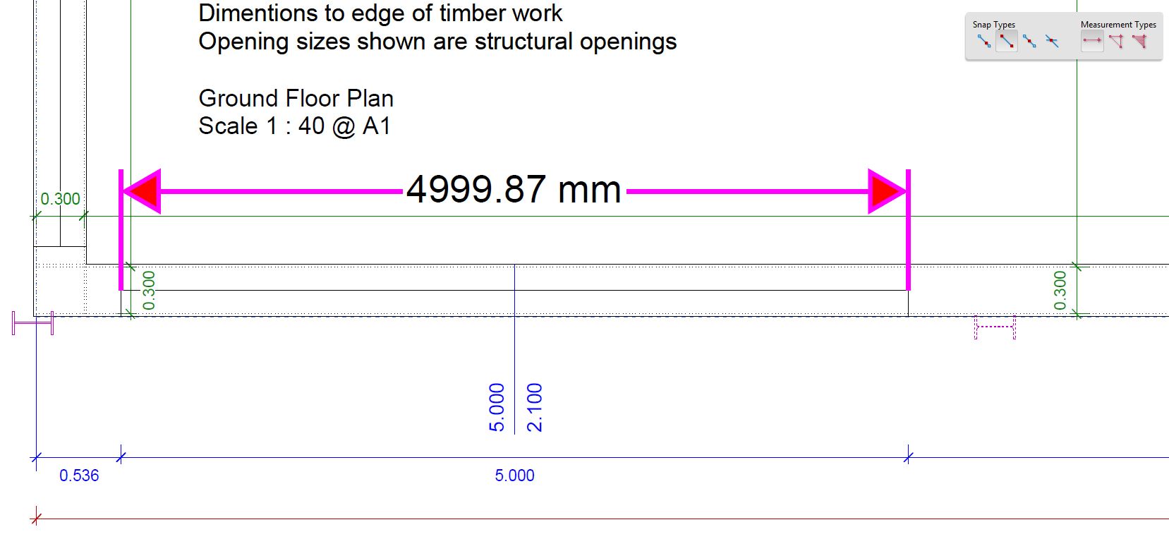
That's not evidenced by your opinion on the capabilities of printing to PDF. @TerryE with all due respect, that's a poorly "printed", PDF and if it were part of the delivery for a paid-for Service I would have refused it. It looks like the result of a "PrtScn". @PeterW The quote of mine you have used is attempting to say that the accuracy of "within 1mm" that I'm suggesting is of the true 1:1 length. Here's one I did not do earlier. This is the corner of the GA drawing for my frame. It's received directly from the Frame designers and I've just opened it up, selected measure and set the 1:40 drawing scale: The opening I've measured using the free Acrobat Reader application is 5000mm wide, as shown by the CAD dimensions, the dimension that the measure tool puts on the drawing is the one that reads 4999.87mm So, accurate to 0.13mm in 5000mm on an A1 formatted drawing that is drawn at a 1:40 scale. I'm zoomed in to 200% to take the measurement. Any fuzziness of the image is due to JPeg compression. There is nothing special about the PDF, it's printed in colour at the correct A1 Size and is 121Kb filesize. I could have picked any of the drawings I have received from the frame designers, or the original Architect that helped with the Design & Appearance Condition, or the Architect I used for some "Passive House" detailing work or the drainage guy that specified the land drains, or even any of my own. CAD Authoring, digital collaboration and digital archiving got its act together years ago to ensure that when the paper-less society does eventually arrive, original drawings archived in digital format can be relied upon to not require legacy CAD systems to remain functioning in order to interpret a drawing. Adobe are at the fore-front of this for 2D data and are pushing hard to do the same for 3D.

-
Well, I can vouch for CutePDF, although I generally use the Acrobat drivers. It's probably worth you getting familiar with the print options, you may be more successful with your printing.
-
Are you suggesting that there is CAD software that is not able to print to scale? While errors can occur, as Ferdinand points out, with physically printing on to paper, not such errors occur when the file is electronically printed to PDF, as long as the Architect knows the basics.
-
That's not what I'm saying Say a Ground Floor Plan at 50:1, correctly printed to PDF, will be able to be measured, within Acrobat Reader, to within 1mm of its Full Scale dimension.
-
PDFs printed from CAD by a competent Architect or Technician will be scalable to an accuracy of less than a millimeter. It's pretty basic stuff, if they're not capable of achieving a to-scale PDF I wouldn't trust them with much. PDFs created from scans are of course a completely different matter, just as photo copies of a drawing would be.
-
The free acrobat reader from Adobe has a measure option under analyse. You just need to select it then right mouse click and set the scale to what the drawing is.
-
If it was 145 SIPs on its own then it was probably a large wood burner as the SIPs will just have met building regs. I'm not sure of the benefit of SIPs for the open plan and vaulted ceilings. With large spans the required increase in timber fraction and cold bridging will drop the "real" performance of a SIP structure. With an I-Joist roof you just go for a deeper I-Joist for the large spans, no negative effect on performance. You may not be comparing like-for-like on your quotes. It's unfair on MBC to compare their twin-stud costs to a 145mm SIP cost. You need to add another 95mm of EWI to the SIP price plus a whole load of air tight detailing. When I costed SIPS and twin-stud, for the same performance the price was equivalent, I-Joist was a little cheaper.
-
What U Value are you targeting? While foamglass is better insulating than other block work, it's not quite as good as EPS, so to achieve a Passive-slab type level of 0.1 U value for the floor and perimeter you'd need roughly 350mm foamglass. But that's not the whole "issue" with SIPs. If you wish to eliminate cold bridging and condensation risk on the sole plate then you need an additional external layer of insulation that drops down passed the sole plate. Where as on a thicker twin-stud wall or I-Joist wall there is an opportunity to place an EPS upstand under the middle of the sole plate so that the inner face of the wall is over the warm floor and the outer face is over a cold ring beam (or on the EPS upstand itself in the case of the twin-stud) and therefore braking the cold bridge, you can't do this with a SIP panel. Hence the need for EWI to isolate the sole plate from the cold side. My experience is that SIP suppliers are much happier about additional insulation going on the inside than the outside, but I believe quite recently Kingspan have started to support EWI on their panels. It's worth looking into the Potton PassivHaus that used Kingspan SIPs, their foundation was very complicated to resolve the cold bridging issues and IIRC they specified EWI to cover down passed the sole plate. Seems to me there are easier solutions with twin-stud and I-Joist walls. Plus you get to use an insulation with better decrement delay and acoustic properties.