
MikeSharp01
-
Posts
5644 -
Joined
-
Last visited
-
Days Won
16
Everything posted by MikeSharp01
-
So you need to work on how to get the views with the minimum of glass or go for high end glazing which may be up to quad glazing and so will limit the light entry somewhat while having good insulating properties. Also remember that the frame of the window is the worst area for heat loss (Sealed unit 3G glass is usually better than the frame) so the more frame you have in proportion to glass the worse the heat loss is U value of the window (Uw) is . On the south side I might try to make the kitchen - dining - living wall more glass to get me some more solar gain and reduce the floor to ceiling glass area (perhaps by having low walls with windows next to the doors). Naturally we cannot see the shading that this wall might have.
-
Looks like a lot of glass on the north side!
-
+1, the challenge is realise the difference between the old and the new. Right now, as I would out how we adjust things here at millstone manor for the new electricity price of 21p (We cannot switch for reasons I won't go into but it is not anything we did) and the fat that our LPG contract ends in about 8 weeks, I know I could add a few 100mm more insulation in the loft, we have 300 already, and save a bit but it may be that switching to ASHP but keeping the GAS for DHW or doubling the HW tank capacity (we cannot use a COMBI as water pressure / flow rate is too low) and using the night rate will help as long as I disconnect cap ex from revenue!
-
They are not good for much but if we fed all the designs for heating systems in and found a metric for measuring how 'good' they were we could get our AI to validate our design in the same way they validate a road sign in a self driving car - classifying is what they are very good at.
-
I wonder how one would one go about designing a COMBI ASHP for a passive house without a storage tank. IE tiny heating load and relatively large DHW demand from time to time? Two ASHPs!
-
If the process encapsulated this then why is it a problem. Perhaps an AI could do it?
-
As you say if common load then it drops out of the equation the problem is that heating load of the building is only one dimension of the requirements, the other is, often, Domestic Hot Water (DHW) and this is where the two heat converters seem, to many, to have different capabilities - IE the combi principle
-
Nope its just an energy converter like the gas boiler!
-
But why does this need paying for surely its pretty simple, perhaps we could work out a straightforward process that would lead to a verifiable design and close the loop.
-
Aspects of this are not quite true. True it will fade, its a powder coating, but it is not true it cannot be repainted although it does take careful preparation, not easy because of the nooks and crannies in the extruded sections, and the right paint, epoxy based is most reliable.
-

Unvented water system in Daughter's house
MikeSharp01 replied to razbaz's topic in Introduce Yourself
How if it is fed from a ring without a timer? Looks like the call for more info is pressing. -
Me too - but not seen that before.
-
So it can be range "In Italy, Poland and Russia, this notation is sometimes used in engineering to denote a range of values." Wikipedia. The windows are Polish, in origin, so that makes perfect sense - good spot @SteamyTea every day is a school day!
-
I am fitting some FAKRO windows and they state a couple of dimensions as S + (3 ÷ 5)cm which I would normally take to mean S + 0.6cm (6mm) but other bits of the instructions tell me that I need a 20mm gap and I only have 6mm. I guess the good old Obelus (the ÷ symbol) must have other meanings that I am not familiar with. If I take it to mean 'between' or 'to' then everything seems to work out. Anybody able to confirm my understanding to save me getting on the manufacturers tomorrow.
-
Some of those stats make interesting reading... over the last 10 years or so the number of residential applications granted has been roughly constant at 75% (ish) it gives the impression of a target. That means 25% or so have not! Similarly the agreed time limit stats which show around 87-88% being done inside the time limit reliably across the last 6 years (Stats prior to that look odd - so assume that the planning portal implementation may have glitched it or some such). Again 12% get delayed. Given the both stats are broadly flat over the period the implication might be that there is no pressure to improve either and so the local planners may have unconscious approaches to maintaining them. So although you expect your application to be granted and in the required time they know that there are some that won't be and there is no pressure on those that are not so long as 75% are granted and 87% are done on time.
-
Its a systems thing - you squeeze it in one place and it pops out in another. People have gone from thinking now is a good time to start to thinking that now is not a good time to start, probably loads of reasons. Materials shortages, sky high labour costs, spent the money we saved in lockdown, this new normal way of working from a remodeled home is perhaps not all it could be, 'what they want me to back to the office' - what's the point of remodeling, too much hassle. Upsides are: the planners have more time to look at and process applications, the sky high prices will drop as less work about, the material shortage will go away as less demand, oh and commuting was not so bad after all. So relax just put your application in and keep on keeping on.
-
Deflection of 25mm from SE, problem for sliding doors
MikeSharp01 replied to Heather85uk's topic in RSJs, Lintels & Steelwork
I think the expected deflection is 22.233mm but is still daft across this span. Were they trying to get the depth of the beam the same as the floor if not then cannot see why it can't be deeper? Also although pre cambering will help with the dead load portion it won't deal with the live / imposed load portion. IE it can be straight under the dead load but will then deflect, as calculated, under the worst case imposed load. The imposed load here is, simplistically, 2/3rd of the deflection so I am wondering how it is derived. The imposed point loading @ 22Kn seems quite high, its like having two ton bags of ballast on a point along them beam, we cannot see the rest of the design but so it could be something like another beam, supporting a floor possibly, coming in from the side, but it feels high. Also remember, but perhaps don't try and work with it - IE by saying we are never going to do it, that the imposed load could be based on / derived from you having a crowded dance party in the room above / adjacent to the beam. -
OK will go that way!
-
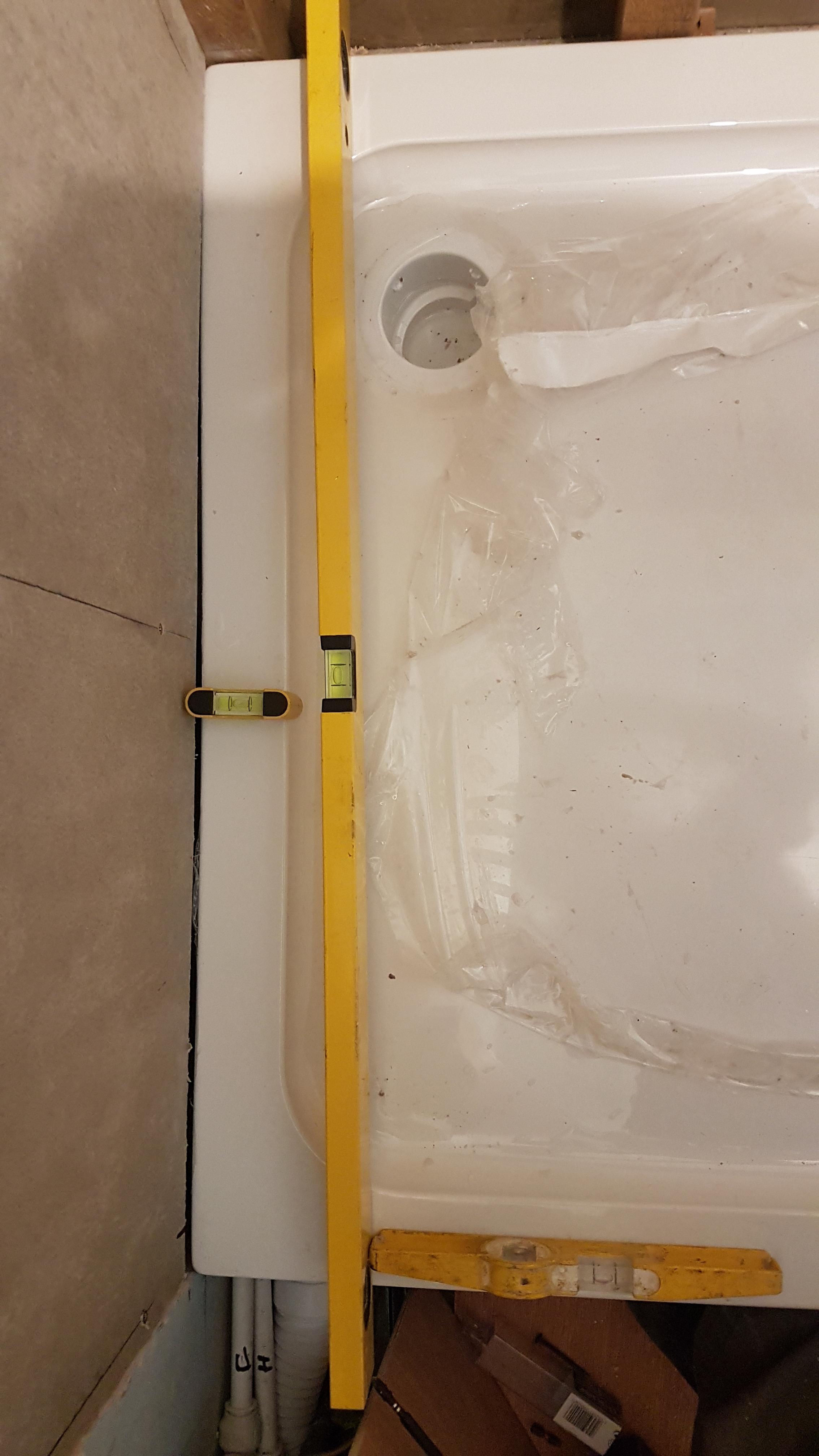
I have the tray dead level and most of it works, its just that edge which is wrong. Anyway we are going to ask the tiler to fit this: https://www.showersealsdirect.co.uk/seals/trimlux-pro-23-sealing-trims-23mm-wide-trims.html and go from there.
-
@NickfromwalesOK, can you suggest what to use to tank the tray to the wall, I can coat the wall in hydro ban and tape the joints. Any ideas?
-
Thanks Nick - trying the gaffer tape test now.
-
I have been struggling to level our daughters shower tray all day and get tge water to flow away. I have it level both ways but the rim at the end foe about 150mm in the middle is sloping the wrong way - as you can see from the picture, the tray side with the short level is level over the whole distance but a bit up at the end which should help the rim issue. The tiler will be tanking it, I guess to the tray and there is 9mm tiles + 1mm adhesive to go on will that be an effective seal against water pooling against it or do we need to get a new tray?

-
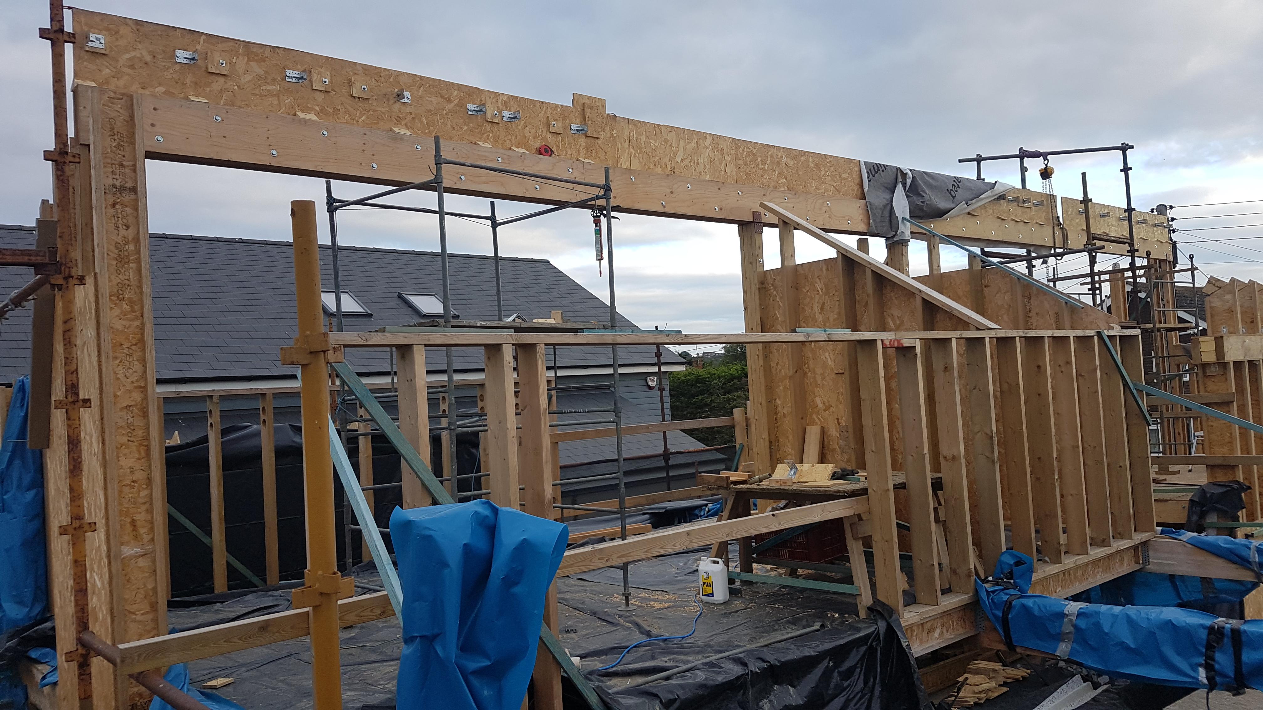
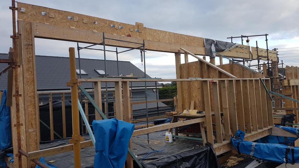
The longest we had were 7m 300x96 I Joists and we slid them up. I also lifted our ridge beam 8m x 240x320 Kerto assembly with headboard by building a scaffold above it and lifting it on a chain hoist, just got the hoist at the balance point which worked well - managed it all by myself! The picture is the smaller front beam lift but used the same approach on the main beam on the left.
-
That looks like slate slab it is standing on! How old is the property?
-
Was the underfloor calling for heat? It may have just stayed put at DHW as it didn't need to move for the UFH - depends on how your controls are organised.