

Nickfromwales
-
Posts
30336 -
Joined
-
Last visited
-
Days Won
297
Everything posted by Nickfromwales
-
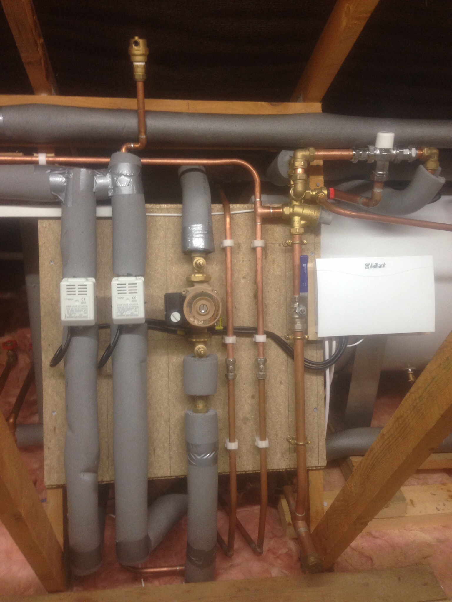
Pic from under the boiler plz. Do you intend to just run rads and UFH the same time always ? You'd be better off doing that TBH with a combi and no buffer. .
-

Glulams are depressingly light-weight
Nickfromwales replied to ToughButterCup's topic in Roofing, Tiling & Slating
Yup. -
Don't you have 2 x 2-port valves already installed and a dedicated pair of flow and return pipes run to the manifold location ?
-
A one day job MAX.
-
Do you have the manifold there?
-
I think @Declan52 has used one that powers back up in the same state
-
What needs doing to the ufh to get it working?
-
When things go wrong - Concreting of UFH slab
Nickfromwales commented on oranjeboom's blog entry in Kentish RenoExtension
-Service temperatures: 40°C - 95°C. -Maximum working pressure: 10bar -Five-layer composite pipe. -Combines the benefits of both metal and plastic pipes. Sounds like you've just removed the protective outer layer. You'll need to check with the substance you use too, that its not going to dissolve the outer material of the pipe. @JSHarris territory there -
When things go wrong - Concreting of UFH slab
Nickfromwales commented on oranjeboom's blog entry in Kentish RenoExtension
Pointless testing with warm water tbh. 6 bar is 4 times the working pressure of the UFH system so if that holds then anything the system can chuck at it will hold too. Just make 100% sure the system contains a 3 bar PRV on the primary side and away to go. I honestly think you'll do more harm than good cutting into that pipe. That magic gel doesn't specifically state that it sets solid, which is what you'll need for the pipe repair. The manufacturer may be able to tell you, but won't endorse its use for this scenario. Me personally, if it were my house, id just backfill with a pissy mix of strong concrete or even a self levelling compound first ( up to a depth of 50mm ) and then screed over the repair. Your only looking to stop any expansion of the pipe tbh, so a few tight turns of PVC tape, 3-4 max to ensure the aluminium NEVER gets into contact with the concrete / other and you'll be fine. Oh, and the guy who did your concreting is a penis. -
When things go wrong - Concreting of UFH slab
Nickfromwales commented on oranjeboom's blog entry in Kentish RenoExtension
Should have added that this pipe will tolerate crazy pressure, and yours will only ever see <3 bar max, 1.5 bar nominal which is nowt. -
When things go wrong - Concreting of UFH slab
Nickfromwales commented on oranjeboom's blog entry in Kentish RenoExtension
I wouldn't cut that pipe tbh. Is it Pex-al-pex? The grey shadow you can see is probably the aluminium layer, so the only bit compromised is the outer sheath. Id buy an external cable resin kit and pour a mould around the affected area to fortify where the sheath is damaged. You could even just back fill that whole trench with the resin, which imo would be infinitely better than cutting and jointing the pipe. FYI ive cut, joint and buried ufh couplers and elbows before with zero fail rate. The recommendation to have the joint exposed is just that, a recommendation. . In your instance I would, if your going to cut out the damaged section, just cut enough to be on clean pipe, and use two 90o bends with a straight bit of pipe between them. -
Ok. You know what your doing now ???
-
Number of times your current soil pipe has needed digging up and / or maintaining ? . Solid floor for me if it were my own build. Why not 250mm of insulation and 100mm of reinforced concrete over the top of that with the UFH pipes in in? A floating floor needs cross ventilation so is inherently flawed IMO. Go 25mm sacrificial EPS over sand blinding, then DPC, then 125mm EPS at the bottom and then 100mm or 120mm PIR atop. Excellenté!
-
Damn he's good lol. The only thing I'd add is that there may be a conflict of supplies in the internal switch if that's got the existing lighting feed in it, and then you take the outside live into it too. @Onoff / @ProDave, any issue with the two feeds sharing the same switch plate ? If not, then if the existing internal switch is a single or double, it can be bumped up to a double or triple ( 2 gang or 3 gang ) rather than make a new cut out for an additional switch to add the extra gang. Getting from the blue square to the green square can be done by fishing the cable down the cavity. Push some slack back on the cable, into the cavity, to get a drip loop.
-
Yes, and kinda. Youll need one cable that powers the lights, live neutral and earth. From any junction you then create your switching circuit. Live to the 2-way switch Common terminal and L1 ofcthe switch goes to the lights as the "switched live" feed. From that switch you then need a 3-core and earth as a 'strapper' between that switch and the second switch. I'll add the configuration later but that's what you need to know for cables .
-
Should have circular knock outs on side / top / bottom etc specifically for a 20mm Swa gland .
-
Beware going to a light switch to get a feed as normally they won't have a neutral in there . Open it up and double check first. Didn't you say you have an external power supply ? If so use that for the feed, and if you want to be flash, do as @Onoff suggested and run a 3-core and earth ( 4-core 1.5mm2 SWA ) to the nearest internal light switch. Then you can switch it on / off from inside or out. Give the cable tobthe bricky and explain where you need it to / from? If he's half intelligent of course .
-
Bath Surround / Boxing In, and concealed pipework
Nickfromwales replied to Onoff's topic in Bathrooms, Ensuites & Wetrooms
I would normally say yes, but the reinforcement of the steel mesh says "chill, Winston", that is going NOWHERE fast. . Its going to be a Carlsberg bathroom mate. . -
Do it, Dave .
-
One word for that. "Bin".
-
Bought a new screen for my boys iPhone. 6 days later I enquire "what's that bright green rectangular thing banging around in the washing machine?" Yup.
-
What about cooling
Nickfromwales replied to Visti's topic in Mechanical Ventilation with Heat Recovery (MVHR)
Bugger. You beat me to it. . -
What about cooling
Nickfromwales replied to Visti's topic in Mechanical Ventilation with Heat Recovery (MVHR)
Search : glazing reflective solar ? -
What about cooling
Nickfromwales replied to Visti's topic in Mechanical Ventilation with Heat Recovery (MVHR)
First question, have you read ( Jeremy's for one ) info re solar reflective coatings for the problematic glazed sections? -
Mine are both hitachi. Just felt lighter to me. Cheaper too.

