Leaderboard
Popular Content
Showing content with the highest reputation on 07/20/17 in all areas
-
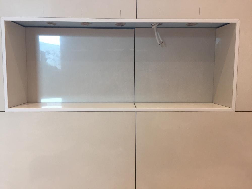
Frame the tiled wall first with your trim of choice. Then tile the back of the pocket, and don't let that set hard before you tile the bottom of it. You have to be able to slide the rear tiles left / right a little to match the grout line running through, so these need to be done in the same set and then left to go off. Cut outs for accent lighting already done and cable in ? Left and right hand cuts go in next. These pics show the trim detail a bit better. I glue these on with mitre bond and activator spray. Don't use to much glue, and keep it away from the face edge or it oozes out of the gap. Less is more. %4 points
-
Suspect the key is to find a very experienced (10 years or more doing similar to what you want) Person from the UK who moved out there to be a Project Manager or other professional, and can recite explicit examples of the problems you wish to avoid, and how a later project avoided the problem. F2 points
-
If SWMBO agrees it shall be done! I like the whole symmetrical, lit alter aspect of the idea. "This is my churchThis is where I heal my hurts" :)2 points
-
i went with BPC (as did many on here) and gave them my plans and they drew up the ducting plan for me and gave me a price for the parts required-> MHRV unit, ducting etc. They calculated the flow rate for supply or extract needed for each room. it needs balanced (as far as i am aware) so the total supply matched the total extact. i think the exast and intake ducts that enter/exit your property need to be at least a certain distance apart (maybe 1.5m but i'd need to check) and preferable on the same side of the building (unlike yours in your sketch). i think if they are on different sides the wind can affect it. BPC didnt charge for the plan they gave me. (wouild highly recommend them as a company)2 points
-
1 point
-
1 point
-
Mad? Most here may concur... I really fancy a lit arch behind the wc now!1 point
-
What radius? You are mad arching them....you are aware of that, yes? ??1 point
-
Nah, it's cruel to persecute creatures of lower intelligence. It is true, though, that women often have poorer spacial awareness than men. It's also true, though, that men generally have poorer communication skills so when their sweeping over-generalisations are heard, they lack the proper verbal reasoning skills to dig themselves out of the very large hole they have just put themselves into whilst being watched by a woman gleefully waiting to bury him. Having spent quite some time marking out dimensions on a factory floor to demonstrate to hubby why I think the architect's proportions for one of the bedrooms in the new build plans, I can confirm that there are also exceptions to most rules.1 point
-
The plan is easy to draw up, but any system will need to be checked to ensure the flow rates as-installed are both sensible and meet the requirements. As an example, I calculated the resistance of every length of ducting, bend and fitting in our system, to ensure that the Part F requirements would be met. When I measured the actual flow rates they were barking mad, massively exceeding the Part F requirements in some rooms, and overall the system was way out of balance in terms of the extract matching the fresh air feed. No designer of any radial duct system is going to be able to calculate the flow rates to the degree needed to make the system perform at its best, all anyone can do is make sure that it is designed so that there is little or no risk of the key flow rates for Part F (the extract rooms and the whole house ventilation rate) being lower than the requirements after installation. I tried hard to make sure that I had an equal flow resistance on both the extract side and the fresh air feed side, by detailed calculation, but then found that the installation screwed up all the theoretical calculations. This wasn't because I deviated from the plan, it was just because small variations in curvature in semi-rigid ducting have a disproportionately large impact on resistance. This is largely down to the relatively small diameter of semi-rigid ducting, with larger diameter rigid ducting, with known radius fixed bends, you can calculate the flow rates far more accurately. Frankly you can design a semi-rigid system very well using some simple rules of thumb; what I did by doing a lot of detailed calculations was a total waste of time and effort. What's worse, I should have realised that there would be a large disparity between theory and practice, as it was blindingly obvious after the event..................1 point
-
@JamieM, attached is the report I drew up, but it's worth noting that it doesn't follow what's in the guidance note, as at the time that I wrote it up I hadn't found the guidance (it wasn't easy to find at that time as it is now). BC accepted it without any questions; I got the feeling that they just ticked a box that it had been done without looking at it closely.................. Mechanical Ventilation and Heat Recovery system Test Report.pdf1 point
-
1 point
-
Apologies - got my Guides mixed up. It was the Domestic Building Services Guide that was updated in 2013 not the Ventilation Guide (still at 2010 version)1 point
-
There doesn't seem to be a newer version available online, the one I linked to is still the only one on the government web site AFAICS. There is a newer, more general, guide to compliance with domestic building regs, but that seems to have very little detail in it: https://www.gov.uk/government/uploads/system/uploads/attachment_data/file/453968/domestic_building_services_compliance_guide.pdf1 point
-
Ian, I am not sure what to say other than to give you both our thoughts and sympathy -- that's from both Jan and me. 20/20 hindsight is a wonderful thing, but you really can't beat yourself up over shit that's happened that you didn't expect. It's bad enough that you have to mitigate and remediate what has happened with the time and cost implications --- without the double hurt of letting the stress and self blame get to you.1 point
-
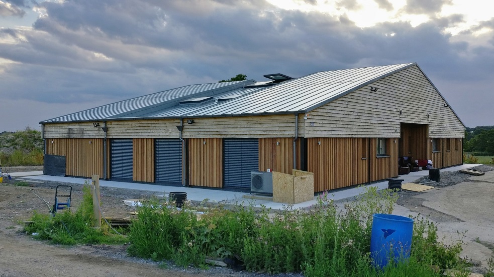
I'm currently demolishing my old bungalow, the larch cladding is original, so it's 80 years old and still in good condition.1 point
-
Pointless doing the whole wall tbh, and more to cut out for the pockets. Lay that panel horizontally and do two full passes if it's long enough, and you'll have enough gap under the cistern to put some off cuts in as catchers to stitch the two boards together where they but together. Freeby ply looking good, and within budget . Ill post some pics later of pocket shelves WiP .1 point
-
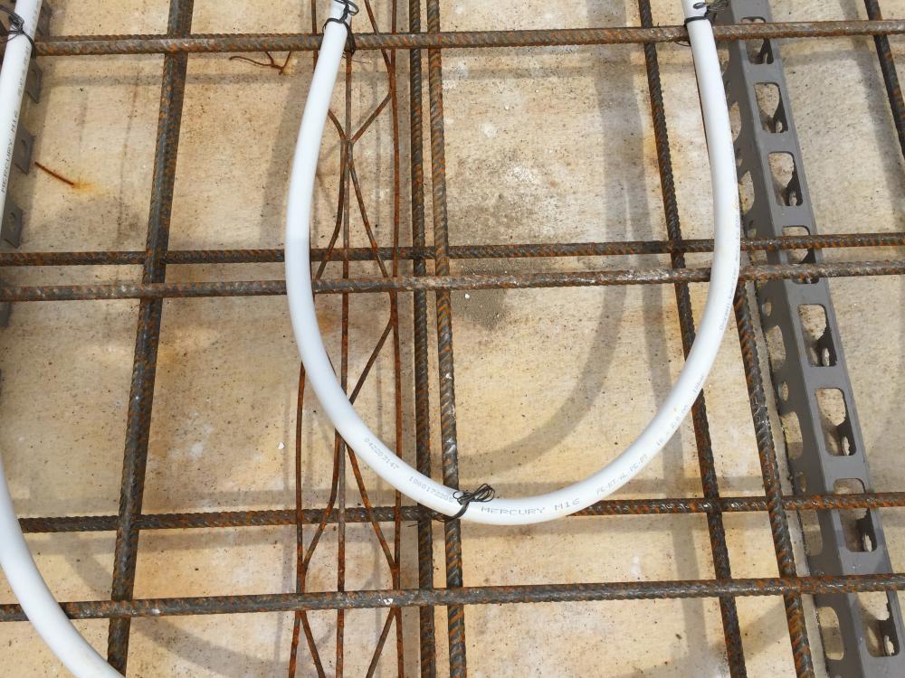
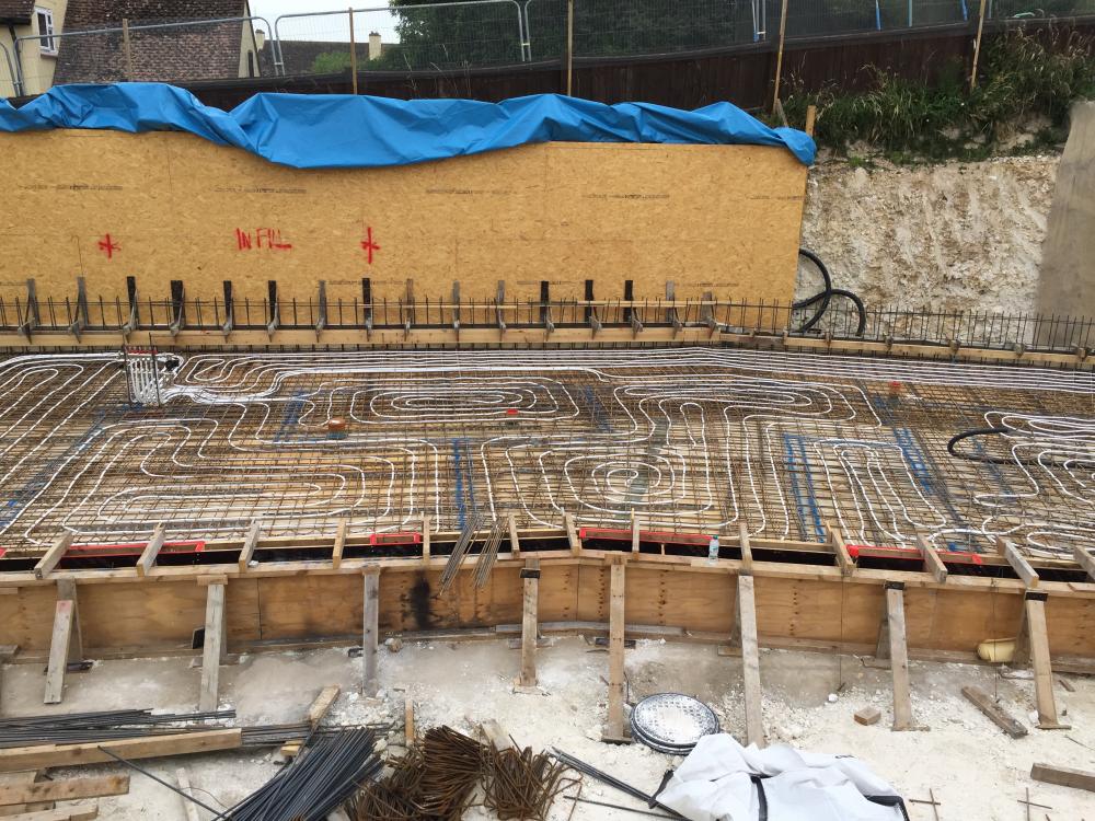
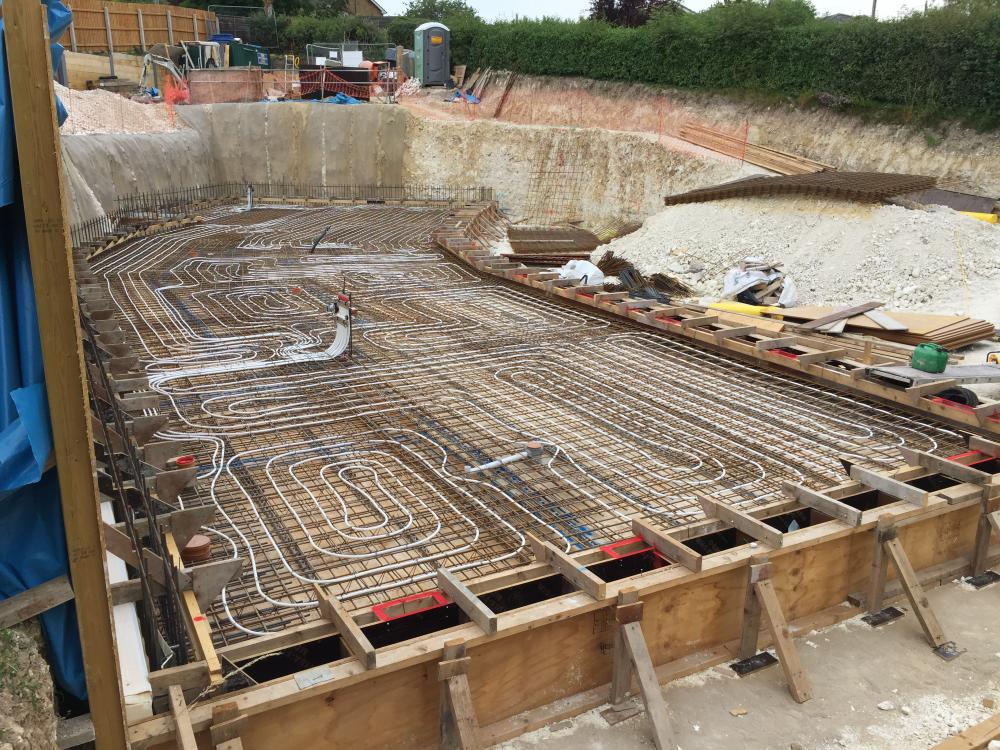
Ok, so I went with 16mm pex-al-pex on the assurance of the installer that it could handle the crushing risk of my mesh-pipe-mesh configuration. It was laid yesterday and pressurised with water to 4bar mid morning in the midrange of a hot day that got progressively hotter until approx 3pm. At one point I told the installer the first manifold was reading zero pressure, but when he checked we realised the needle had gone off the scale beyond 6 bar and around to hit the underside of the zero stop-bar on the gauge (It's a serious sun trap of a site) ! The other manifold had also climbed to over 6bar. This morning following a wet and much cooler night both manifolds were reading below 2bar and have (along with the weather) remained there through to this evening. Tomorrow is pour day. I want to add some pressure back but the ufh contractor is reluctant even though tomorrows forecast is cool. So far as the mesh sandwich is concerned i've a feeling it's almost a good thing - the greatest vulnerability so far has been where a foot can land on pipe that spans a 200mm square void in mesh as per photo here. The top mesh significantly reduces these instances and does also seem to distribute the weight of foot traffic fairly effectively. That said we are treading as carefully as viable. At this stage i'd say pex-al-pex is probably ok tied to mesh that sits directly on insulation but (to my surprise) I'm so glad I didn't ditch the anti crack and leave it tied to suspended mesh...if this were anyones scenario i'd say ensure every inch of the pipe follows directly along the line of mesh bar (including the loop turns....so impossible I think). So it's a tense day tomorrow but if we get through it the fun really starts; The pic showing the wall of osb....thats single sided shuttering along there which will require around 24 push-pulls to support it in that walls pour which will exert around 20 tons of pressure. All the push pulls will have a minimum of two thunderbolts 150mm into the slab. So we're drilling circa 50 holes betwixt the pipe maze!!1 point
-
Nick, This is what I wrote: I'd not recommend using an indirect small buffer as we have, but having said that I did calculate the heat transfer rate for the lower temperature and it massively exceeded the ASHP output. Newark were happy to replace the wrong tank they'd sent, and gave me the surface area of the coil in it, so I could see whether it had any impact. As it turned out, the indirect coil was rated for around 40kW at 55 deg C, so handled 6kW at 40 deg C with no problem at all. In practice we get no measurable difference between the buffer temperature and the ASHP flow temperature at all, and the heat up rate from cold seems to match the ASHP output. As above, I'd not go down this route by choice, but I made do with what we received by accident. The reason I suggested a small direct TS instead of a buffer was just to eliminate the need for a PHE if using it for DHW preheat. It would be a lot simpler to just run the cold water into a small TS coil for preheat and then run it to the Sunamp PV, electric boost heater or whatever.1 point
-
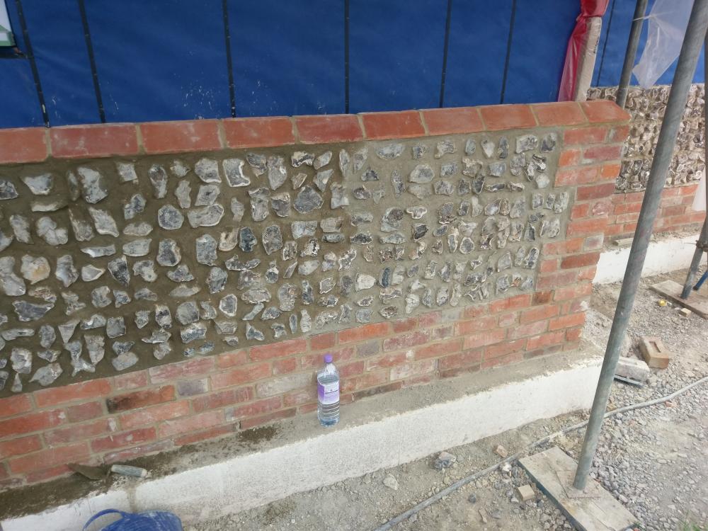
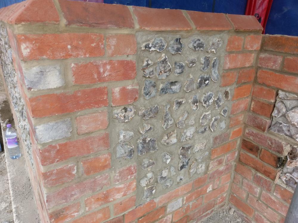
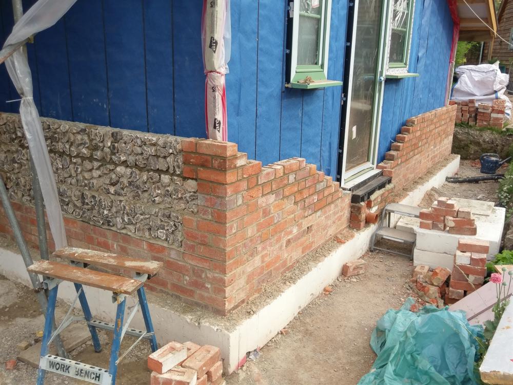
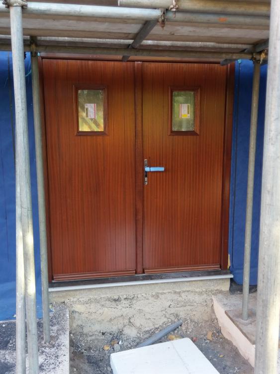
Ok, so a month later and the windows are still not sorted. Will update when they do get sorted but to be honest its been one of the most frustrating and unbelievable periods of the build. We have no glass in the 3 sliders which should be with us Friday, if not its another three weeks due to factory shut down. MBC have been absolute stars about it all, and have agreed that we can start the brickwork on the single storey utility room before the air test and insulation. Due to the cost of the window delay (all ready at over £6000 for rental costs etc for the 8 week delay ) i have had to make some cutbacks. one is doing thhe brickwork myself. Considering the bricks are over 200 years old i think it looks good for a complete novice. We had to compromise on the flint blocks but they look sort of okay. I cannot brick up tp the door yet as it has been put in wrong.1 point
-
It will never happen. He wont allow it to be bought and will first need to design it in CAD then make it (one day). In fairness though @Onoff is very familiar with WIP (Work In Progress).1 point
-
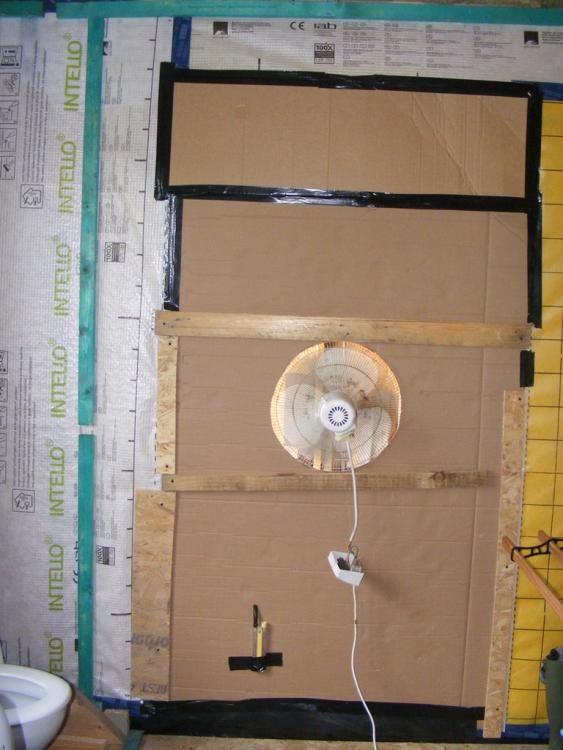
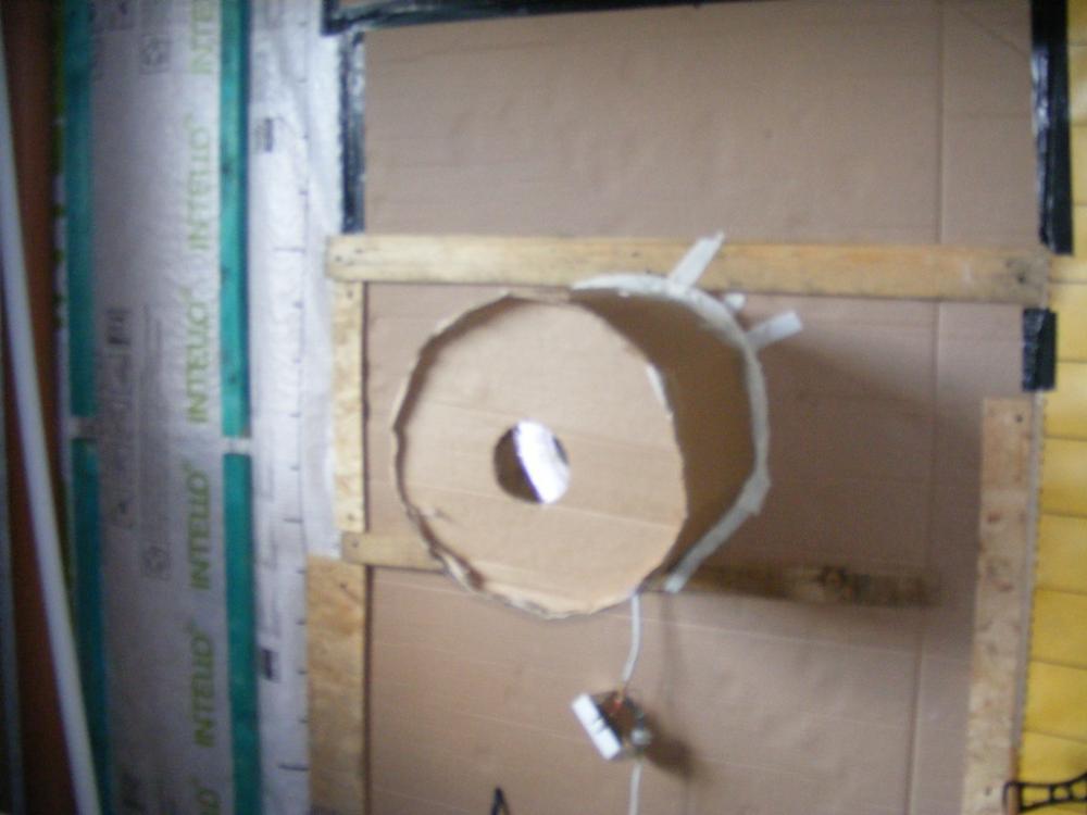
Something I have been wanting to do for a while is see how air tight I have managed to make the house, but without paying £hundreds for an official test. So take one old desk fan. Some bits of wood. A large piece of cardboard and a roll of duct tape. The first thing was just to run the fan on full speed and go around the house looking for leaks. I found a leak under the front door where it was not sealed to the floor properly. A leak in the loft at a tricky detail between the ridge beam and the OSB cladding, and a leak around where the mains comes in and cables go out under the floor. All fixed with a bit more tape and detailing. So now I have a house where there is no perceivable leaks coming in anywhere. The flow going out of the fan seems very small, and it's certainly holding a good pressure (if you open a door you can feel the rush of air enter, and hear the fan note change as it is no longer working hard) Time to try and measure something? Firstly the pressure. Normally an air tightness test is done at 50Pa. It was only when I looked up the conversion I realised that's a tiny pressure, about 2mm water gauge. So I set up my manometer, one side connected to "outside" the other side vented to the room. It's very hard to accurately measure 2mm on a U tube manometer, but I am sure it was somewhere between 2 and 3mm. So in the right order. How to measure the airflow? Simple. Just measure the air flow rate through the fan. Well my little anemometer would not register the wind speed entering the fan, it was too low to get it's impeller turning. So I had to do something to increase, the airflow. Decrease the area, AKA the "flower pot" principle. I didn't have a 15" flower pot, so I made one. The hole in the "top" is 110mm (because a bit of drain pipe was handy to draw around) Now the air flow was high enough to measure. 2.9 metres per second. A 110mm diameter hole has an area of 0.038 M2 So that gives a volumetric flow of 0.11M3 per second That's 6.6 M3 per minute or 396M3 per hour. Now my house has a volume of 480 M3 So that equates to 0.825 Air changes per hour. I'm actually a little disappointed with that. I had hoped for better. But let's not kid ourselves that this was in any way an accurate measurement. At least it enabled me to find and fix a couple of air leaks, and I am now reasonably certain there are no air leaks of significance. Feel free to tear the method or results to pieces.1 point
-
1 point
-
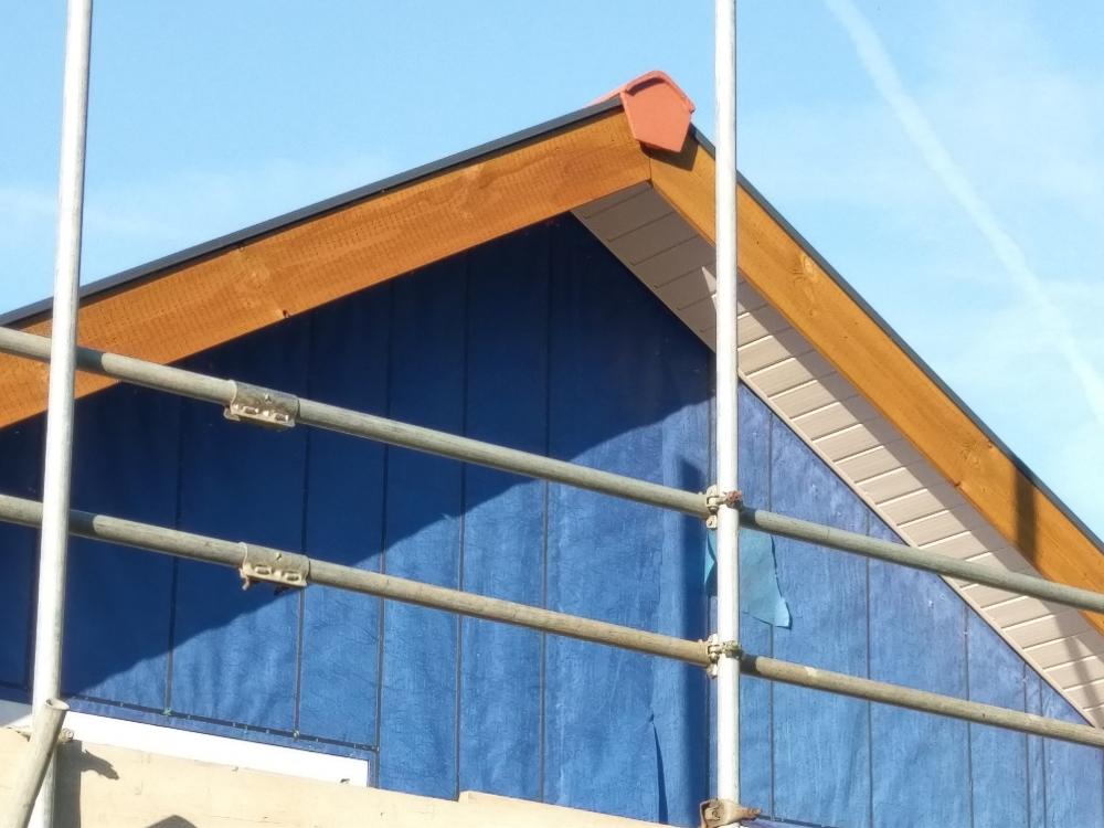
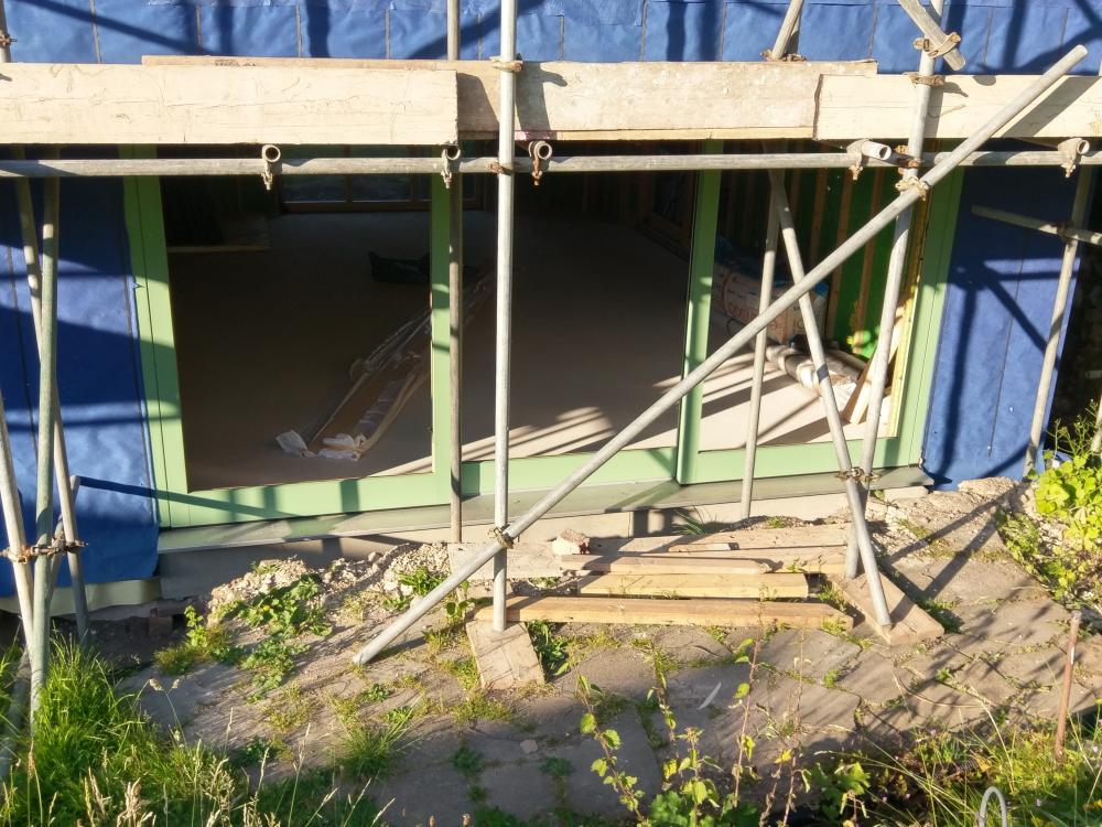
So its been a few weeks since I posted an update. Frame is 90% battened and sealed. MBC left as windows and doors had not been fitted. Roof is finished including gutters fascias and soffits etc. The windows and doors are a different matter. Its been and still is a bit stressful. Don't want to say much as it is still ongoing. Do have a couple of pics. Hopefully we will make some progress with the windows and doors next week. As you can see with the sliding doors there is no glass fitted so house is not secure. As we have night time visitors i dont want to order in equipment until it is.1 point
-
Been speaking with BPC and they say no cleaning is needed as their pipes have an anti-bacterial internal coating Phew :-)1 point


