


Mr Blobby
-
Posts
616 -
Joined
-
Last visited
Everything posted by Mr Blobby
-
That's what I thought. Thanks.
-
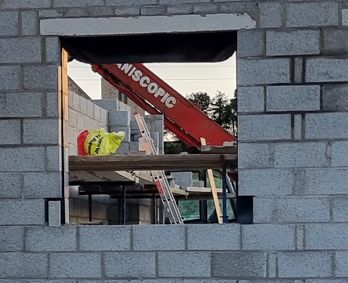
So my bricklayers like to crack on with the blockwork and put sills in later. Like this: There will be some heavy 3G windows on the sills so naturally I want them properly bedded in and perfectly horizontal without any risk of moving / twisting. I worry that the mortar bed above and below the sill at each end won't be properly filled if sills are slid in instead of placed down and built up. Should I tell the brickies to build in the sills as they go, or does it not matter?
-

Ceiling diffusers for MVHR
Mr Blobby replied to renternolonger's topic in Mechanical Ventilation with Heat Recovery (MVHR)
Lindab airy valves look differnt. @Conor, are the flat plates slightly lower than the ceiling? -
This stuff I think. https://www.rawlinspaints.com/home/fire-retardant-paints/steel-intumescent-paint/5227-thermoguard-thermocoat-wi-ultimate.html The tin is in the wheelie bin. I'll go and check when back on site on Tuesday.
-
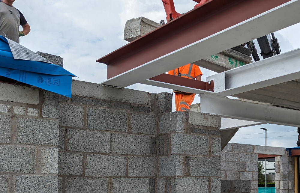
One coat. My builder laughed when I asked if it needed a second coat. On the tin it said the sealant was optional. AFAIAA the BCO has never questioned the paint, as long as he can see it. I'd be concerned about that beam being cantilevered too! I can see that's how it looks from the picture above, with a body hiding the detail. This picture shows it better, witht the steel supported, taken from a differnent angle:
-
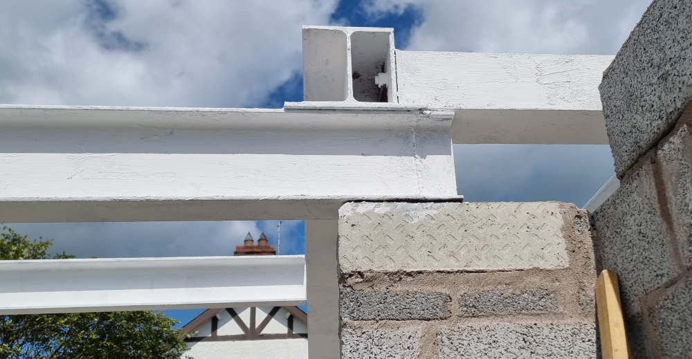
Yes, the paint company had the steels plan and calulated the required quantity. No I agree, I think the paint is probably a waste of time but building control like to see it. ..Painting wasn't as bad as I expected. But then after reading all the comments here, I was expecting it to be hellish. 😬 Yes its thick and hard work but my builder actually pitched in to halve the pain. Which was nice of him. And here's the finished beam, with a bit welded on to take it over the middle of the padstone and beautifully painted. 🤗
-
Holy crap, our flow rates are more than double part F recommendation. Thanks for this, I'd not looked at that document before, just assumed the flow rates from the M and E guys must be about right. Yes, they will be dialled down 👍
-
Your doors sound good. Which ones do you have? eclisse? Another?
-
Would you not have to pay capital gains tax here because you could end up owning two houses so subsequently disposing of one is a txable event?
-
I'd assumed the same cross section as the one installed. I'll ask...
-
Structural Engineer has got back to me about this RSJ (and some other things hence the delay). He says the bearing is "a bit short". He says it works in calculation at 210mm but if replacing the steel then he advises 250mm bearing to give some additional capacity. He has suggested an alternative to replacing the RSJ may be to weld a piece on at the end. Glad I checked this🧐
-
Surprised to hear that. Why? Who Says? Architect and builder say so because I'm doing it so it costs them nowt. There is a lot of painting to do though. Builder says do it after the hollow core slabs are in place but before then sounds more logical as @Conor says. Our BCO is allegedly easygoing on this. Any tips on the painting to make my life any easier? What's the sealing coat?
-
Indeed. I have run this past the SE and waiting for a full answer. There were some other issues on other padstones being installed that are smaller than specification 🧐 so this is part of a wider enquiry. I would have made that steel a bit longer to sit further over the centre of the padstone, but that's just me wanting done as best as possible rather than to min spec to save costs. The irony is, however, that it is probably just as well it isn't 😉 Yes. That's exactly what our SE has asked. Medium density 7N is the answer. So standard blocks. Interestingly enough the only some of the bigger padstone sizes supporting the bigger steels are explicitly specified on the SE drawings. And nothing AFAICS about how much steel should be resting on the padstones. And this padstone is not one that the SE has explicitly sized. The single slab between the two steels should rest on the L-shape at the end on the left. That's the theory anyway. If the slabs are the right size and installed in the right order of course. I have a choice of paint or paint. I'll be doing the painting myself so its nice to hear this is a shitty messy job to look forward to🧐. The funny thing is that (I have since remembered) a gap is needed above that padstone to run some services including MVHR ducts in the ceiling void to the kitchen. So, while I may have made that RSJ longer, its a good thing that it doesn't sit across the whole padstone as I have don't have good alternatives to run the ducts 🤪

-
Slabbies (is that a thing) are coming out to measure tomorrow. Good point about the slab support within RSJs. l'll ask them about this tomorrow😉 ... going back to my original question @Conor, do you think there would there be any benefit in making that RSJ longer to be better supported by the padstone? It just seems to me to be on the edge and longer would be better. Or am I being a bit OCD here 🤪
-
You mean this: That'll be about 180mm Hollow core slabs. But this RSJ supports further beams that in turn support more hollow core slabs so I think this bit may be quite important 😬 Tell me about it 😩 .. The RHS in the first photo is ok-ish, its the LHS that's a bit on the edge I think.

-
I think steel beam marked with 2300 should be longer so that it is supported by more of the padstone. Should I get it swapped out?

-
The plan is to use solitex plus breather membrane to wrap the ends of the hollowcore slabs for airtightness. From what I can find online, this is what others have done and acheived good airtightness scores <= 0.6. What I don't get though, is that Solitex doesn't seem to be airtight. So why use it as an airtightness membrane? Are there any other robust membranes that are also airtight? Any recommended products here?
-
Thanks @Conor It sounds like you have the same insulated screed my builder is suggesting. From alpha flow screeds in Omagh? Did you then poor a standard screed on top of the UFH pipes? How thick? I think we're looking at 30 insulated screed and then 50 ISH standard screed on top.
-
As it says, I have the option to run a couple of UFH loops in the FF bathrooms, which are above the kitchen diner in our passive build. I figure it would be handy for cooling as much as heating but as far as I can tell, the clip rails would need to be attached to insulation and then the screed on top. Can I attach the clip rails directly to the hollow core slabs? My builder and plumber were appalled at the suggestion, but I think because of the labour required, not because it is a bad idea. Has anyone on this forum ever attached clip rails directly to the slab? Is it impossible? I only expect to install two loops for the bathrooms and a bit of landing so not a massive area, about 30 m2. To install FF UFH our builder has suggested a 30mm insulated screed under the UFH pipes to clip the rails to as it is failrly maleable for a number of days and easy to fix to. And he says it gives a sturdy and level base for the rails. The screed then goes on top. My concerns with this are the extra weight of the extra 30mm screed. Has anyone ever installed UFH on insulated screed on the FF? Or should I just stick to PIR. Or is it just a cr4p idea to install the UFH on the FF to cool the hollowcore slabs above the kitchen? Maybe the current heatwave is affecting my thinking 🤔
-
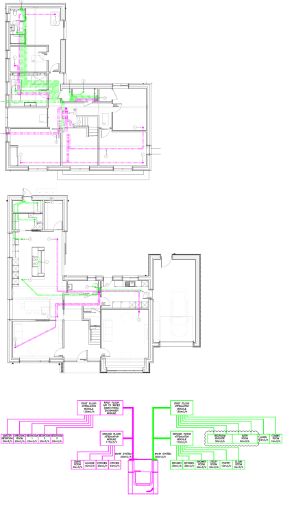
We have an MVHR plan originally from our M and E guys which I think is OK, like this: The unit is in the loft under a warm roof, in the centre-ish of the house. The external vents are through a North facing gable end wall. The first floor heat exchanger will probably be replaced with a bit of UFH upstairs, but apart from that, is there anything fundamentally wrong with the layout and ducting plan? The third diagrm shows more extract than supply vents. Is that an issue for balancing? I ask because a leading MVHR supplier refuses to engage with us and give us a quote until after we pay them a fee to (ostensibly) rewrite the ducting plan.
-
If 3-phase is close to the cost of a single phase connection, then get 3-phase, just to future proof extra car charging, or whatever else. Three phase will make it easier to have more PV on the roof as well.
-
Good question! I dug out our old quote and it was for 30 kVA so by my maths thats 75 Amp per phase. I think this is just below the threshold at which NIE tut and shake their head. It is unlikely you will be charging three cars at 32A simultaneausly and even if you were then chargers like ZAPPI and the Tesla wall chargers can do load balancing to make sure you don't exceed you grid supply limit. Without load balancing you could do something simple like 1 charger 3-phase 16 amp, 2 at 32 amp single (different) phase so that would be a maximum load of 48 amp on two phases and the remaing phase with 16 amps demand from the charger could go to the ASHP and the hobs and stuff and still not exceed 75A. But then reducing to 75 Amps may make no difference to your quote in your circumstances, but worth checking with your DNO just in case.
-
Is that 100 amp per phase per property you are requesting? That seems like an awful lot if it is. When I first enquired about our 3-phase connection last year the DNO told me there is a threshold that I should not exceed in my request. I forget what it is now, but I'm pretty sure it was less that 100 amp per phase. Maybe talk to your DNO about resubmitting your application with, say, 79 Amps per phase.
-
Another ASHP flow and return question
Mr Blobby replied to Mr Blobby's topic in Other Heating Systems
Reading other threads on this and it looks like 28mm in armaflex through 80 mm conduit build into wall. How does that sound? What about the power, another conduit through wall to the isolator switch outside? What diameter? So three holes then. Is there any value in positioning the ASHP on the East wall instead of North to get some sunlight in the morning? I have options here. -
Timber Cladding, Zinc Guttering, Brise Soleil and External blinds
Mr Blobby commented on Thorfun's blog entry in West Sussex Forever Home
Thank you very much @Thorfun for the link to Powell blinds. We are about to order the Trojan AV90s from Powells that have Z shaped slats. Are you still happy with your blinds? I take it there have been no issues.




