Gus Potter
-
Posts
2155 -
Joined
-
Last visited
-
Days Won
26
Everything posted by Gus Potter
-
But I know you know, you've just have had better things to do! Yes you get the direct shear and the bending force also creates additional forces that cause localised failure in the masonry. The maths bit I know you know. But it's how you apply the maths to this particular problem of a fixing that is not something that most folk wake up in the morning thinking about unless you are @pocster. We have the direct shear and the bending moment that I have decoupled so we have an approximation of the shearing force just at the point where the fixing enters the wall. The assumtion in this model is that we allow the masonry to crush under the fixing rod very slightly just at the point of entry to the wall. We know the compressive strength of the masonry so we can say.. how much area of masonry do we need under the fixing to resist the load. My guess was 20mm. Now we assume the force acts at the mid point so say 10mm in from the face of the wall. At the embeded end (the force is in an upwards direction here) we assume the same and that give us our lever arm. But for us to calculate the actual capacity of the fixing we need the quadratic function / solution because as the bearing length changes so does the lever arm and thus the forces. What I outlined above is just a very simplistic model. In reality the rod is bending and subject to curvature, the masonry is elastic to some extent and not rigid thus the bearing preassure over my assumed length will not be unifiorm. The masonry is not a uniform material. You could get closer mathematically by using a finite element model. The fag packet calcs above would get you on your way provided you leave say 40% margin of safety at preliminary design stage. In practice Hilti /Fischer say just put their fixings into things, test them physically and produce capacity tables. That is where the problem occurs on BH as folk are using fixings that are into old brick etc and they have not been tested for this.
-
Bar bending and reinforcement quantities! Have written this as I hope it helps all who are doing everything from ICF, piled extensions or just using rebar. I often do these on small domestic projects. I sell this as an extra to the Client by discussing first what type of builder they may want to employ. Take two cases: 1/ A house extension.. a few piles with a ring beam. Here your local builder (or you) could maybe get a piling contractor that leaves the pile heads. These are commonly designed at SE stage to be up to 75mm out of alignment and still be code compliant. Next the builder has to figure out how to connect the piles to the ring beam, the shuttering to say get the concrete cover right and all the bars in the right place. Now your local builder may find this a challenge. I say.. hey I'll do the schedule and a shuttering detail. Your builder can then send my schedule to the benders for pricing, make the shuttering and I'll nip by and check it before you pour the concrete. If you want the builder to sort it all out it will probably cost you more than getting me to lay it all information wise out on a plate for the builder. All they need to do is send my schedule out for pricing.. no hassle for them and if no hassle less tends to be added to the price. Or you can get a ground worker that will sub out the piling and do the ring beam.. but someone has to coordinate all this and that is something that comes at a hidden cost.. and you have to take a leap of faith that they are doing it correctly. Better to spend more on good pragmatic design info than have a bad day when it comes to the concrete pour or worse.. once the concrete has been poured and you discover all is not as you expected. Stepping up to say an ICF basement. Here I would push the Client to pay me to do the steel (bar bending) schedule. In fact I would be reluctant to do the job unless I had sufficient design control over it and be able to check on site. What folk don't realise is that when you bend rebar it is not an exact science (bends vary a lot!) and that you need to be very careful to maintain concrete cover, the correct lap length and make sure the concrete can be well compacted at particularly the corners and junctions as that is where you often get leaks. The folk that provide the ICF stuff don't cut you much slack if your bars and in particular the bend radius is a little off. The steel fixer will use what they are provided with and while they will often do their best they can't make a purse out of a pigs ear. Remember that rebar is very heavy and if a rebar cage falls over it could kill someone. I want to make sure that the tying of the bars and temporary stability bracing will be sufficient for it to stand safely during the construction phase. ICF suppliers.. their interests / priorities are not the same as yours when it comes to rebar and so on. Yes some SE's don't do schedules.. years ago it was part of an Engineers training to design a concete beam / slab and produce the bending schedule.. I still remember learning how to do it. The main thing for me is that if I do it say for a basement or say ICF, a retaining wall I have to really look and draw/ model how it is going to fit and if it can be built /poured. It's almost like a last design safety check as when you have to sit down and do the schedule / shuttering you can spot things that you may have missed. It's like another design review/ safety check. If it can't be built as per the design then it's not safe. I could pass design responsibility to say.. well who is going to carry the can.. that is what you need to ask. The sad reality these days is that few designers want to carry the overall design responsibility as modern Clients are often not willing to pay for what they percieve as an extra. Why.. because modern professionals often don't explain (and have often not been taught how to) to a client how they can make savings at the end of the day. I minded to blame the telly.. too much Sarah Beany, Homes under the hammer and Grand designs etc .. well I'm not going to blame myself? If you have the skill to convey to a Client that your way is the most cost effective, efficient and delivers and the Client is not of like mind then you need to walk away from that Client, let them get on with on it. Projects like that often only lead to disappointment on all sides.
-
Hi Jilly. Yes builder is onto something here. It might be worth seeing if you can fix a bearer to the external wall. Use that to support the high end of the roof. At the outside corners on some thing like this you could use a couple of essentially galvanised scaffold tubes to support the outside corners. If these look too slender then you could use a 76mm circular hollow section to get the appearance right. Your issue is going to be the ground if BC get involved. The loads are really small so you if you need to get this by BC you could say.. look this is a canopy, if so you may need to decouple from the dwelling and argue that it is akin to a smoking shelter and if it settles then so what. Here as the loads are so small you could go back to your driveway design and say.. hey the area under the canopy is the the same make up as the drive and this is designed for a 5.0 tonne axle load so the canopy on a concrete platt will be ok?
-
Hope this helps give some pointers that will help you frame your questions in the way you want. A 7.0 N/mm^2 unit strength dense concrete block wall weighs about 1800 to 2100 kg per m^3. An aerated (say Celcon ) concrete block wall weighs about 400 to 900 kg/m^3 and has a varying unit compressive strength. Remember that the light weight blocks contain air pockets.. the more air pockets the less concrete material to resist the loads so lower compressive strength but better u value. To make an aerated block the same unit strength as a dense block you need to use more cement for example and that is one reason why they are more expensive. The density is not usually a primary issue, it's the block strength that is considered first. In principle there is no reason why you can use an insulating block provided it has the same compressive unit strength. Just check you are not in aggresive ground for example.. always check with your|SE before you swap out materials. Also, check the mortar mix in case the blocks need a different spec. If the mortar is too strong it plays havoc with aerated blocks.
-
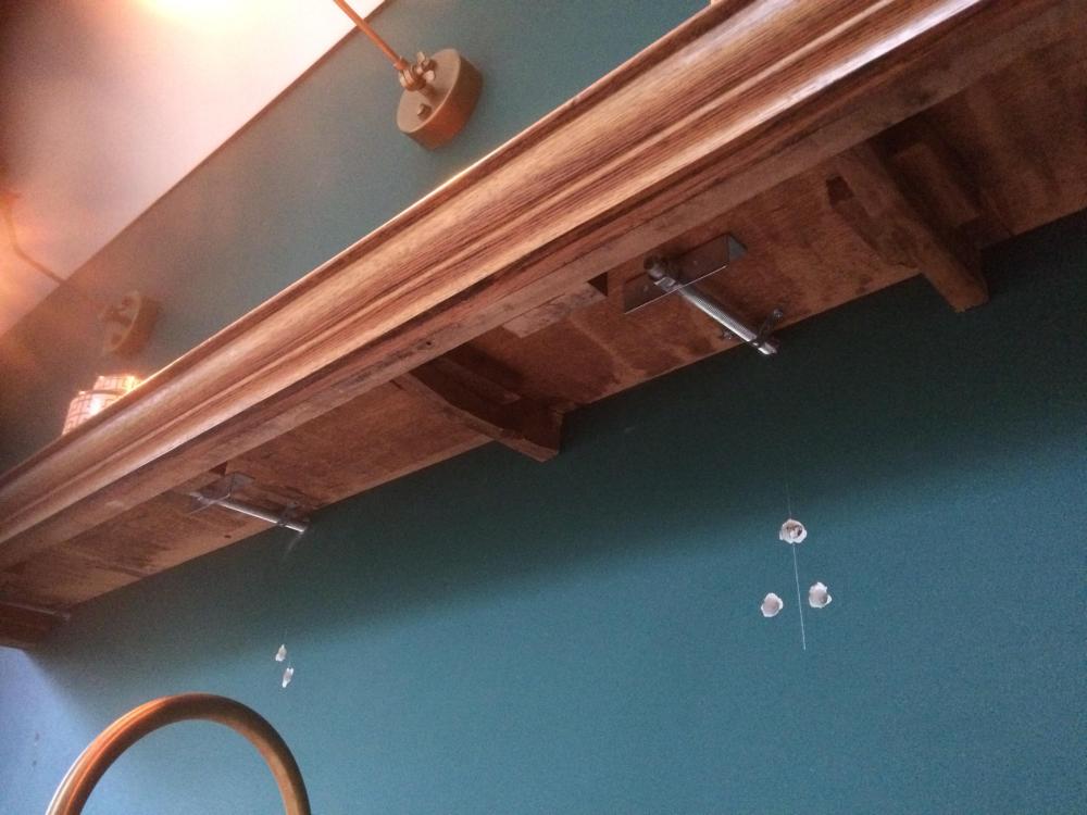
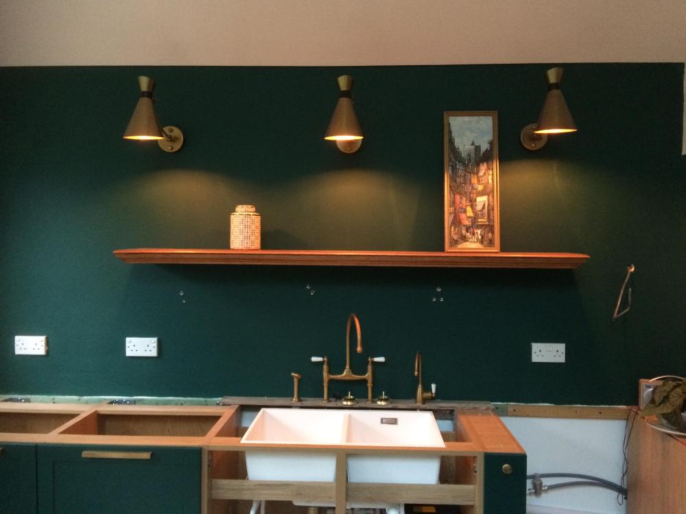
For ones into masonry have about 70 - 80mm embedment with really careful drilling so did not punch through the half brick thick wall. The ones in the photo are drilled into timber studs. These are structural studs but only have a modest axial load and very little wind loading so not getting bent top to bottom. Good point markc. Yes these kind of fixings are subject to a bending moment as well as shear. For non safety critical fixings like this you can calculate it out as a fag packet check. Have to say I did not do detailed calcs as it is my own house but if asked here is roughly how you prove it for a non safety critical fixing. The key is to let the shelf sit a fraction off the wall so it does not pry the fixing.. a tension force. Lets say you put 100 kg on the shelf and it is 2.0m long and your fixings are at 400mm centres so direct shear load per fixing = 100 * 0.4 / 2.0 = 20 kg per fixing. 20 kg is about 0.2 kN.. call this the working load.. an unfactored load. The 20 kg acts straight down the direct shear. A M10 /M12 threaded rod in a typical resin in soft brick will carry about 1.0kN to 1.2 kN in direct shear... all looks good. Until you see what @markc say about cantilevers. Say your shelf is 300mm deep and it is loaded front to back with books. The centre of action of the books is 150mm out say. Now you have a leveraging (bending) effect also.. which is 0.2 kN * 0.15m = 0.03 kNm.. seems a very small number until you start to think.. hey this rod only goes a little into the wall .. 70mm , the bricks / timber are soft and just where the fixing goes into the wall you have a highly stressed area of brick / timber. Lets say here that your first 20mm of rod penetration is required to resist the compression under the fixing.. and you need about another 20mm at the far end of the rod where it wants to move upwards. So the effective lever arm is now 70 mm less (20 + 20) / 2 = 50mm. Now a bending moment can be what we call decoupled into an up and down force in this case. So we convert the bending moment into an up and down shear as follows. 0.03 kNm/ 0.05m (the effective lever arm) = 0.6 kN .. and this is the extra force that is generated as marc says. Now we have to add the 0.6 kN force to the direct shear force = 0.6 kN + 0.2 kN = 0.8 kN. All of a sudden we have significantly increased the load on the masonry / timber although in this case it still looks ok. One other check to do is to check the rod in case it bends or deflects too much. That is why I tilted the rods up at a bit of an angle so when the shelf is loaded it lies level. Remember that the shelf in the photo is just for a few pictures and stuff... no where near 100 kg. For safety critical stuff we start with a fag packet sum to get a feel for things then we check carefully. We use some theory from steel column base plate design and write a quadratic equation and or use excel to solve iteratively.. then we get close and do further checks and so on. You often see something like this on the side of a motorway or the base plate stantions for railway pylons.. the base plate sites proud of the concrete base.. your shelves are the same .. but hopefully cheaper! There you go.. a bit of theory on flying shelves for a Saturday nights fun. That said this can be applied to all sorts of cantilever structures that require fixings into masonry.
-
Sorry.. Yes SE = Structural Engineering.
-
Floor loading understanding check please (long(ish) & maths content)
Gus Potter replied to dnb's topic in Boffin's Corner
Hi dnb and all. I'm a bit late to the table with this but will have a go at exploring as this kind of thing drives early design decisions / cost analysis / cost curves when you are planning your self build, extension or just renovating part of the house. Firstly have enjoyed reading all the other posts. Everyone makes great points. I'm going to have a go what goes on behind the scenes first then touch on some of the in's and outs. Ok you are doing a domestic dwelling, you get some calcs from the SE that reference various design codes. Could be Bristish Standard 5268 or Eurocode EC5. Both these design codes (as are nearly all design codes) are based on the probability of a loading event occuring. For example lets take snow loading on a roof. In the UK we design houses for a snow loading that has a recurrance / return probability period of 50 years. But we could get two snow events two winters in a row that may meet the maximum predicted fall over the next 50 years and then nothing for the next two hundred years. But if we design for a longer return period say snow in two hundered years then houses would become so expensive that we could not afford to build them. Also we need to look at the overall risk over the whole UK and what would be the potential loss of life and balanced that against the benefit to society of taking a pragmatic approach to how we calculate loadings. We may of course not get anywhere near the design snow fall. All I would say is go back and look at the last time all the farm buildings collapsed, they were designing these on a two year snow return period and had got away with it until they didn't. That was a main driver behind changes to the argicultural snow design part of the code. @dnb The floor loadings of 1.5 kN/m^2 ( about 150 kg/sq metre) roughly equates to a value of what has been deemed on basis of probability to be a reasonably safe figure given normal human behaviour in a house. What Engineers then do is to say.. lets put a factor of safety on this loading to account for the fact that folk may a bit daft and have a big party. Lets also add a factor of safety to the materials in case the timber joists you have may include one or two that have a load of knots or just be a bit of duff timber. Also lets say the floor may not be truly uniformly loaded. But we then say.. the floor boards will mitigate by spreading and sharing the load out a bit so we add a bit back in. Now you'll often hear a builder saying.. I have been doing this for years..etc and nothing has fallen down.. I say.. not yet. What SE's (unless you have briefed them) don't do is start out by saying.. someone is going to not use their common sense, go nuts and turn a domestic floor into a library floor. The codes prescribe different loadings for libraries and storage areas and they are much more onerous. I think you may need to come clean with your SE! For all. Here you need to be careful when doing your research (delving into structural design) as the BS code is what we call a permissible stress code. The factors of safety on the loading are all lumped together and not immediately apparent, but the EC codes split this out between a visible load factor and a material factor of safety. In summary though design to the two codes gives pretty similar results, there are caveats but for another day. A big elephant in the room here is that while you may get away with a big stack of book shelves on a house with solid timber floor joists it won't fly with engineered joists as they often buckle and crush at the supports unless you have designed in end struts and so on.. and if they do buckle / crush so will anything else that is relying on them for support also fail! Big trouble. What happens is that one end of the joists get much more heavily loaded in shear even though the overall load on the floor has not increased. @SteamyTea Below is copied a bit out of the BS 6399 part 1 code for loadings.. you can split hairs here but you can see that you may have a "reading room" case thus your 1.5 kN/m^2 live floor loading now jumps to 4.0 kN/m^2 or 2.4 kN/m^2 for each available vertical metre of storage height. You can see that you are treading on thin ice here! That's my thoughts so far folks but if there is any interest then I'll do another bit on defections, preliminary sizing and costing.. the other things you need to think about when you are embarking on your journey. To finish @markc makes some good points about concentrated loading.. but the first thing to do is to get the general concept sorted and then you deal with the concentrated loads (see table above) and check something won't punch through the flooring locally. Once you have done this you go back and check the whole design again as a complete system.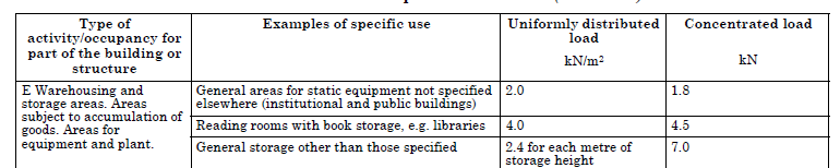
-
I've made a few of these. The ones for taking heavy stuff are made out of 2 bits of oak faced MDF 18mm thick glued together to give a thickness of 36mm. I glued a solid oak edge trim on and it looks passable. The main thing is the the fixings. Here I resin anchored two M12 rods into the masonry behind and tilted them upwards a fraction. Rods project about then offered up the shelves and gave them a "dunt" so the rods marked the back of the shelf. Then drilled them out to the rod depth and slide them over the rods. I also made another lot (out of a recycled bit of oak furniture) that go onto a TF stud wall, they don't project so far though, ~ 275mm. Again I experimented and drilled the studs and used resin. A year later disaster has not struck.. I will obviously come clean if it does later on.. promise. Have attached photo of the lighter loaded shelves.. will try and take photos of the MDF shelves once I have tidied them up.
-
Yes as Joe says.. photos are the key. That's you underway.. the build has started!
-
Welcome from me. You'll find all sorts here from folk just starting out to some real experts in their fields. I'm into SE type stuff but always learn loads on BH so anything you can chip in is appreciated. Great friendly site, a good few great characters too!
-
Hi Jilly. My own thoughts are: Have a Firestone rubber roof on part of my own house, from memory it was the thickest they offered 1.5mm thick. Performing well so far. Also, as I did it myself know how to fix it if hit by astoroid. Fibreglass, yes does well, but less easy maybe for DIY / local builder to maintain? Also edge detailing and you need the weather to be ameniable as the resin cures If you want have a look at Sika Sarnafil, you get an approved installer to install, bit more expensive but is a well tried and tested system. Felt and bitumen.. used to do this but the weak points can be the seems / joints. For me I would go for a more modern system even though old sckool at times myself.
-
Installed channel glass balustrade wobbles
Gus Potter replied to rhymecheat's topic in Windows & Glazing
Hiya. Sorry to hear about your experience. Good news is you have caught it early before anyone got hurt. Hope this helps and for all. When you design glass ballustrades the following steps are roughly this: 1/ You get the Clients spec. Say height, configuration and if it is say domestic or industrial / public ( say a pub) loading. 2/ Obtain the manufactures' data sheet. This tells you how the glass will perform under load coupled with their track design. They are mostly tested as a unit / system 3/ Look very carefully at what they say the substraight is.. often they say "concrete non cracked ".. or "solid" etc... so could be steel. And this is where it all tends to go badly wrong, things become unsafe and the continuity and liability in the design breaks down. To get say a BBA, CE mark & comply with the standards the manufacturer bolts their glass and track to a very solid test bed in a lab and checks to see if it will carry the load (not fail) and not deflect too much also a failure.. the 25mm often mentioned. The fixings are bolted to the test bed and so long as the fixings don't fail when connected to the test bed all is good. If you read the manufacture's literature this is often where their liability ends. Some don't even specify the fixings! They just give you a hole diameter in the track (could be side or top mounted etc) and the grade of aluminium that the track is made from. I have seen this from a German manufacturer for example. If you are say an SE you then need to calculate the tensile and shear forces in the fixing based on the track dimensions. Check to see if the fixing will pull through the track, check the fixing for all the forces (tension and shear) and often the key is what the fixing goes into and if it can resist the forces. Then you as an SE need to check to see how much you substraight will bend (deflect) by as this is included in the 25mm deflection at the top! Now this is tricky but can be done. All BC sees is the total deflection.. there is only one cake to share deflection wise. In general laymans terms the fixing is subject to mostly tension (the levering effect from the glass), the shear forces (sideways forces) are relatively small. But imagine the glass is like a long pinch bar.. there is a rotational force at the level of the track, this generates a rotational force called a bending moment.. and brickwork is very unsuited to resist these type of forces unless it has a huge amount of dead weight above. In other words you can't put bending moments into the top of a brick wall and expect any good result. You can put bending forces into concrete if it is adequately reinforced or thick. Yes I think the manufacturer is likely in the clear... will be caveated in their spec. The installer should have known better so they are in the line of fire. In the round while I think you have a good case for a claim against the installer for negligance that resulted in damage to the wall. You may want to say.. look.. I'll keep the glass and track, may sell it on ebay and that will cover the damage to my wall due to your lack of experience / knowledge. OR you can sue me as I have not paid my invoice and see how that goes boys and girls. But before you do make sure you have got an SE on board that can justify why you installed a potentially dangerous system.. contrary to the manufacture's recommendations and if you have broken other regs such as CDM etc.. as we will need to have a look at that too! In the round, with a bit of careful thought you may break even cost wise. -
Garage foundation design - borehole plant ducting
Gus Potter replied to Kelvin's topic in Foundations
No reason really. A caveat though. When you create duct routes or routes for drains under founds you need to just check the ground water flow and the type of soil. What we want to avoid is creating a route where water can flow in a trench under the founds at a significant rate. A big risk is in say soft fine sand and fine silts as the flow of water can wash away the fines and reduce the bearing capacity of the soil around the trench. Some amount of seepage is normally ok. If you take say a power cable coming into the house it normally has a hockey stick.. a short duct but the rest of the cable is normaly just backfilled with normal soil. That said the cynical may say it does look a bit like the SE is kicking the can down the road and buying time. -
We too, but not hundreds of sq m, that said we have one room that is big and a U shape. The U shaped room has a concrete slab under part of it, the bottom part of the U.. the rear house extension part and a chipboard suspended floor which forms the legs of the U which is where we knocked out the back of the house to make a big open plan space. Flooring is 15mm fairly high end engineered flooring. The flooring interlocks with some clever plastic bits to join the butt ends. You can also glue it if you want and fix down with adhesive. In the end I used the basic foam underlay to create a bit of a slip plane as the concrete and timber floor will move by different amounts. Yes, the basic foam underlay acts as an insulating layer but when you look at it it's not much of an insulator. My though process was partly.. if it gets damaged / wet can I easily lift some and replace, what if we want to change it later (hope this never happens), if it's glued down will be a nightmare to lift. If we did want to lift it then we could use the unworn bits in other rooms maybe. In summary it's all been down a nearly 18 months so full year of UFH cycle.. heating on and off different humidity levels and all still looks tight. What I would do is if you have some really heavy furniture then maybe just move it from time to time to let the floor move / de stress? We faced a dilemma in that we have an island unit in the kitchen with waterfall sides. Conflicting advice was offered. Do you put the floor down first and then the water fall sides on top or do you do the water fall and butt the floor up to it. In the end we put the floor down first and put a bit of plastic under the bottom of the waterfall sides to make a slip plane and then trimmed off. So far no signs of overstressing on the island unit and the flooring. All looks good.
-
Garage foundation design - borehole plant ducting
Gus Potter replied to Kelvin's topic in Foundations
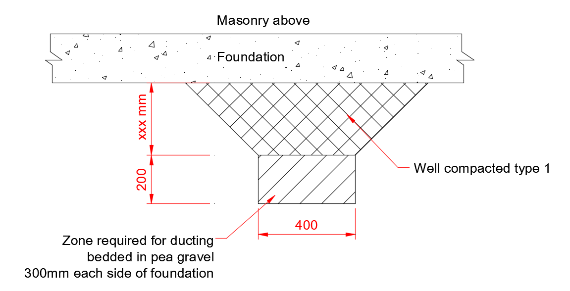
You could try sending them something like this, have sketched a couple of alternative cross sections, put your own dimensions on. Also mark on the plan drawing where the ducts cross the founds, hopefully not near the corner of the founds. The SE will maybe come back with a change in the bedding etc but they probably want to know where the soft spot will be from the ducts and how much the may need to bridge over. Pity they did not ask for the info sooner.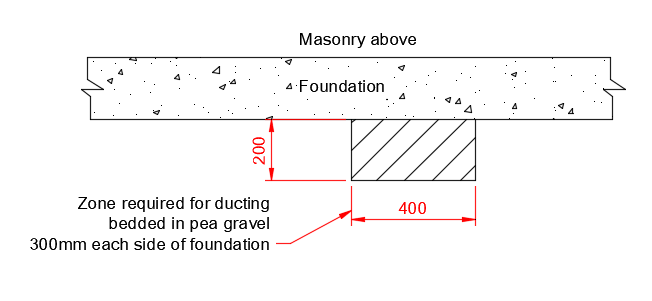

-
Where is the kWh price heading in 2022?
Gus Potter replied to epsilonGreedy's topic in General Self Build & DIY Discussion
But they are a nuclear armed state. The guy probably has not much less to loose personally. Yes the risk is small that this will escalate into the use of tactical nuclear weapons or an intentional realease of nuclear material into the atmosphere from one of Ukraine's reactors.. but it is not a hypothetical risk.. it is plausable.. would you gamble on 1:500 odds (year return period) .. say the same as dam failing over a small UK city? The consequences are severe. Much will depend on China, not just how much influence they have over Putin but most importantly how much influence they have over who they see as the inevitable successor to Putin. That is the a big picture. China will take this right to the edge and gain as much advantage as they can. I'm sure part of their calculation will be to weaken us in the west as much as they can economically, that way they will extract the most. Of course the Chinese regime are corrupt, their leaders are interested in their own personal wealth first and foremost. But what we don't know is how much risk and how far they are willing to go. Xi is up for "re election" .. he needs to play the strong man and has a bit of trouble at home. If you look at it issue in this way it may be worth a discussion? It may be that China offer Putin an exit.. like Idi Amin was offered and died of old age pretty much. That is one possible outcome that could go a long way towards stabalising the current situation. -
What counts as a medium or high end finish?
Gus Potter replied to smart51's topic in New House & Self Build Design
Spot on! For me good design starts with the structural fabric. Then what and how is the house to be used for, is resale value important, or do you want a forever house that you can adapt not just in terms of layout but to make it easy for you to change things as fashions and your taste changes over time. Structurally, if this is your forever home the medium / high end design takes into acount your future needs and what we don't know we don't know to some extent. The way to deal with this is to not push everything to the max in terms of structural design.. I'm not saying you over size everything.. you just make sure that you build in enough say sideways sway resistance to a building to let you take out some walls later and not put lots of point loads down onto a pad foundation that is just hanging in there. You can identify parts of the structure that are getting pushed, some founds may settle / shrink but still stay within the movement limit and be fine SE wise. But all that movement ends up somewhere and will manifest in your finishes, could be cracking, sticky doors / windows etc. Things you can do for example are if you have a bit open plan space is to incorporate shaddow gaps / reveals. This lets you redecorate small panels of wall in a room without doing the whole room, thus quickly over a weekend you can reinvigorate a space without having to change the whole space. That is designing for your own living not what a developer thinks you need.. medium / high end? If you design the fabric of the building to last and move less than say a "major developer house" then you can probably work it so that you can afford "high end" stuff at a medium end price and it will last, still function and look good. Unfortunately as Jilly alludes to, if you have no style then you need to do a bit of work on this aspect, it is a learnt skill to some extent so worth putting in the effort. This way you can get a lot more for less, it just takes time. -
Like it! Some pretty smart lazer cutting there in the webs. Can I be rude and ask what the brackets cost?
-
ICF and Foundation design
Gus Potter replied to Renegade105's topic in Insulated Concrete Formwork (ICF)
Happy to chip in with what I know. But I / BH folk need to know more about the ground before I / we could be of any real help on the nitty gritty. Funnily once you get a handle on it an insulated raft is pretty simple to design. We have been designing insulated raftes for many decades in the commercial sector so it's nothing new. With a good set of drawings you should be able to russle up a few quotes from contractors.. also approach the folk that do high end farm sheds.. they will also quote you. It's bread and butter stuff for them. Check them out on the farming forum, if they get the thumbs up from the farmers they have passed a test. -
Cool. Are the gallows brackets structural?
-
ICF and Foundation design
Gus Potter replied to Renegade105's topic in Insulated Concrete Formwork (ICF)
Hope this give you a few pointers and encourages further discussion on BH. Great to see folk posting about founds and so on as it's a big worry when you are trying to do a self build. Putting a price on the founds is like chasing cats. But how many stories is the house? and what is the construction? The bit that I'm looking at first is your pile depth. I think there is something else going on here. Ok could be worse. Have you had a good site investigation done? For all there are two kinds of generic site investigation report. The first is what we call a factual report. Here the Geotechnical Investigation company comes; maybe drills holes (could be a shell and auger rig, maybe window sampling, excavate trial pits, measure / monitor water levels, maybe some gas monotoring (if you are unlucky).. there are many "tests". A key one is to determine what is in the soil.. is it contaminated, is it acidic or alkalie. Is it going to shrink and swell? What they then do is report the facts only.Thus a factual report. The interpetive report means they (soil investigation company) take the findings of their tests and provide a more in depth report that tells you things like.. how much weight you can put on the soil and at what depth, how aggressive the ground is in terms of it attacking your concrete and the rebar in it. To get a good interpertive report the superstructure / piling SE needs to be involved early so they can tell the investigation team what you are thinking of building and where you may want to put load. This is the most efficient way of doing this. Yes it will cost you more in professional fees on the outset but not that much when you consider the savings that could be made and most importantly justified. But there is a difference in price here as if you provide an interpretive report as a site investigation company you carry much more liability, thus you need to charge more.. and often folk don't want to pay for that at an early stage.. they wait until their back is against the wall.. At some point the buck has to stop. I get factual goetechnical reports and have to interpret them. Thus I take on the liability and charge accordingly. If a Client has got an interpertive report then I can use these values directly and my fee goes down. Again for all. It is really difficult to compare piling costs in particular. Roughly it's common to think of piles as a vertical column that transfers the weight of your building down to something solid. But from time to time the piles are subject to other loads. Say you have 10m of really soft clay on hard rock and a two storey house on top. Now often you'll find that if you install say a 150mm dia pile and just socket it into the rock (200mm say) you can put a lot of load down it. The socket is often required as the rock will have a bit of a weathered surface / a few fractures due to ice ageing. All good until you realise that you need to stop the house from blowing sideways on a windy day. The pile will just move sideways as it pivots at the bottom and the clay etc up the side just compresses. To stop this happening you commonly make a series of flat portal frames (like B & Q roofs but just a but flatter). Here we make a stiff connection between the top of the pile and the ground beam. All of a sudden the ground beam is doing two things: acting as a beam to transfer the vertical loads to the piles and acting in conjunction with the piles to stop the building moving sideways. You can then see how the ground beam may need to increase in size. There is a balance to be struck here.. is it cheeper to make the ground beam much larger.. almost on first glance too large or do we increase the pile size and make the ground beam a bit smaller? Where lies the most economic design? Last but not least if you have clay that can shrink and swell. When it shrinks it can still grip the pile so the piles has to carry not just the load from the building but a bit of the "hanging on clay" When the clay swells is can really grip the pile and tends to lift it up. Often swelling is not uniform and this too can push the pile sideways. I hope the above give you a bit of insight into the "life of a pile"! @Renegade105 Post the info you have and know about the site. The trees.. often this can be mitigated and if you are talking about 19m piles then I think (guessing) this is not critical to the design. It may well be that the raft is an option but before you embark on this you need to know a lot about the soil, ground water flows, topography of the site etc. Also there are other options available, ground improvement and so on. Post the info you have.. you'll get plenty suggestions here on BH, can be helpfull if even to rule things out. -
Good to hear. You have quite a lot of options with a new roof. Existing roofs are a bit trickier as you invariably end up adding more load to the roof so you need to check this out SE wise. I have a warm flat roof on part of the house. Starting from the underside. Skimmed plasterboard, 195 x 45 timbers @ ~600 centres, 18mm timber sheeting, vapour barrier, 200mm of PIR, 18mm timber sheeting and then EPDM. Yes.. you can hear birds etc trundling about and heavy rain, but we have a roof lantern and like to hear the weather and wild life. This roof is over our living area.. would be different if over the bedrooms, worse if you live by the sea and have gulls waking you up at 3.00 am at times. Yes you can put an acoustic make up on the inside under the main joists. Problem is that if you have a lantern the roof thickness becomes even more of an issue. But you can also use a Sedum roof. That will act as a good cushion. You can make an allowance for a bit of extra load. As I have put an extra layer of sheeting directly under the EPDM I could also put some thin slabs on runners or stools on top of the EPDM.. less risk of a puncture, again this I think this would work well. We are plagued with slugs here so have an idea of putting some small plant pots etc up there for a bit of fun. Yes it may mean that you need a few extra timbers at closer centres. But the good thing about a warm roof is that you can do this without loosing performance due to repeating bridging of the joists, all the wood is on the warm side so it has no impact on the performance of the roof. The good thing about the above is that often you find that when you are interfacing a new roof with an existing house it ends up too high and you can't flash it in easily under the upstairs windows. Also, with a lantern you often need a 150mm kerb. If you put sedum or slabs on top you keep them back from the perimeter a bit so you still get the kerbs and flashings to work as you have not increased the roof thickness where you struggle for height. There is another benefit around putting stuff on top and setting it back a bit. It can soften the roof edge and help you not end up with fascia's and verges that look unpleasantly deep. Lastly you can also look at inverted roofs... these are more common on commercial stuff and can be tricky re drainage etc. Have a look maybe to just rule that option out.
-
Have had a look at page three.. oh happy memories Temp shows a bottom drained set up.. I think. Hey ho! Some may say.. "would you see it from a galloping horse?" I say.. get it wrong and you void the warranty on your sealed units and risk water ingress. I don't have a horse BTW so am talking..
-
You can use a thin 2.0mm plaster stop bead to create a shaddow gap. You let it all settle down shrink etc and then mastic to air seal if need be. Have done this on my own house but did the plastering myself as it is really time consuming to set up the bead acurately. Could not afford it otherwise. Have to say.. needed a bit of time off after (sore body) so hat off to @nod
-
I've had a look at page 4 of the posts, I think I should see some small cover plates on the vertical face on the outside of the window frame.. face drains. Page 4 at my end shows a bottom drained setup where the water runs out onto the sub cill and outwards. Am I having a "senior moment"