


Gus Potter
-
Posts
2339 -
Joined
-
Last visited
-
Days Won
29
Everything posted by Gus Potter
-
Pay particular attention to this, also the drainage flows and loads (surface water.. hard standings matter) if you are increasing occupancy. This can open a can of worms so beware. Probably does not apply to you but if a new build then you need to watch out for land contamination on the site as this can have an impact on the type and cot of water pipe you need. If in doubt ask now rather than get caught out later.
-
@GEO-PAR I do like what you're trying to achieve, very elegant Architecturally. Deflection is a key.. will come to that in a bit. I think you will have trouble with that at the clear span of some 1800mm. The way it is detailed is potentially risky in terms of failure of the stone lintel and bits falling on folk. Here are a few comments (with my SE hat on) on the structural design of something like this at this span. Firstly though for all stone lintels can work well if the span is short (image by @scottishjohn) and you have masonry above that is bonded to the top of the stone (no dpc / cavity tray as this acts as a slip plane) the composite action (stone lintel and masonry working together) form an arch thus the actual load on the stone lintel is small. For a piece of stone spanning ~1.8m say with a shallow depth of 150mm the primary design force is going to be a bending force, unless you have a huge uninterrupted wall above which forms a bigger arch. @GEO-PAR the detail seems to show the bottom of the Catnic in contact with the top of the stone. The Catnic is more "bendy" than the stone thus the stone could carry a lot more load than you expect not just its self weight. It takes a lot of finesse to design something like this that is not common bedtime reading. I would revisit your detail before progressing. The quality of the stone, type, mechanical properties and knowledge of that is vital. If you have ordered and paid for the Catnic then you need to work around that. This is something that interests me as I love a bit of stone.. but to make more detailed comment I would need to know all the loads from above and how the floors etc are supported on the inner leaf for example. In summary.. I would recommend that you check with your SE that your detail is ok... as it look a bit off to me based on what you have posted so far.
-
Asking for a friend? Why do you need to break up and remove the slab?
-
To PIR, or not to PIR, that is the question.....
Gus Potter replied to G and J's topic in Heat Insulation
It does. You have experience so play to your strengths. There is nothing like fitting the insulation yourself as you will get it right, builders are working against the clock. DIY insulation.. often delivers better quality of workmanship / air tightness which is a key requirement. You've obviously got a grasp of the basics on keeping a house warm while avoiding / mitigating condensation risks. In terms of using software... unless you really know your onions and understand the limitations of any software then trust your common sense... which it seems you have. As an SE / Designer I use a lot of different software design tools but always carry out a "sense check" as ultimately I'm responsible for what I design. Jeremy produced a great spread sheet which I've interrogated. It's a great tool to get folk enthused.. he did a great job here and a service to all. The spread sheet has it's has limitations but you can't knock Jeremy for that. At the end of the day I think it will boil down to buildability and what suits your skill set rather than the cost difference in the various types of insulation delivered to site? Remember that one day of a good trades person that you don't have to stand over can cost £200 -250 a day say. -
To PIR, or not to PIR, that is the question.....
Gus Potter replied to G and J's topic in Heat Insulation
Was this the cost of the material or did you take into account labour installation cost, buildability, wastage and how complex it would be to make air tight. Often when I design the insulation I look at these things and think.. yes the higher spec insulation may give a better U value but getting it properly installed on site properly is going to cost much more overall. For self builders there is often no point in trying to be smart. If you get too technical a lot of local builders will either not do what you want them to do.. then you have a barny or they charge a premium.. and then still not deliver the quality of workmanship required for some of the high spec insualtion. Service voids are handy, the spark will love you for that as they don't like cables buried in insulation. Start with your structural TF stud depth. Then think about who / what kind of contractors are avialable / how much you are going to do yourself. Look at the structure of your TF.. does it have loads of dense clusters of cripple studs, noggings and so on.. then think about the spacing and wastage of the insulation, air taping etc. Keep it simple and buildable then use Ubakus say to add weight to your common sense assumptions and understanding. -
This is true.. but to completey change the installation method, pile construction (cased, end and friction bearing assumptions, flight auger etc) and drastically the driven depth when close to a boundary raises questions.
-
Good to hear from folk outside the UK. I spent some of my SE training with a cold formed steel outfit that were big in AU. We did cold formed steel sheds, some of these were for the big mining companies with huge floor loadings and height requirements. I loved designing some of the stuff and the R & D. Australia has such a varied climate. There is a big band in the North that is in the cyclonic region... very windy. Then they have the bit on the east.. high altitude and snow.. then all types of soil and termites! Then there are the hot bits that we in the UK normally associate AU with. @Aus_Doug where are you going to be building location wise?
-
Boundary retaining wall failure
Gus Potter replied to SilverShadow's topic in Party Wall & Property Legal Issues
What a good post and example of approaching things pragmatically. For all. Retaining walls like this often don't have an indefinite life span. A bit of tecky stuff. From time to time the wall gets frosted and this causes the soil behind the wall to swell up a bit right at the top where it can apply a good overturning force, mind you it needs to be a hard prolonged frost. This pushes the wall sideways as the ice crystals grow for example. Then you have settlement of the retained soil and surcharge loading, can be just the wieght of a big tree locally, trees can be heavy! Now you may have heavy rain and this excess water causes the soil to weaken behind the wall so it shoves the wall sideways and then you can add a bit of water pressure. Any trees or big shrubs can push the wall sideways as the roots grow. If you have a timber fence attached to the top or down the side of the wall then the wind loading can push the wall. Now in goetechnical terms (we have many) it's easier for the soil to move than to shove it back into place. We call this active (the soil moving) and passive soil pressure.. shoving the soil back into place. It can often take roughly 2 -3 times the effort to shove the soil back to where it was. Now once the wall moves a bit then cracks tend to develop in the retained soil. These can get filled with muck.. in other words the wall often never can recover it's position... it a slow progessive failure. Odd that there is no mention in the deeds. Anyway. If I was you I would try and figure out what has caused the cracks in the wall. Do what you can to mitigate this if it is on your side. Then have a chat with the neighbours and say.. I've done everything I can on my side to stop it geting worse. Let's see how it goes. Any good will on your side will stand you in good stead later. -
Steel spine staircase
Gus Potter replied to crispy_wafer's topic in General Self Build & DIY Discussion
I love these... I think they are elegant. SE wise pretty straight forward to design. The rub is the connections at the top and bottom of the steel rectangular section.. often the builder leaves a mess with inadequate vertical and torsional (twisting) support. I know a bit but I think.. it's Marc.. that knows more.. can't remember his online name off the top of my head. For me it's the detailing and marrying it all up with the glass. SE wise the rectangular steel section is made to a tolerance.. not always straight and true. To that you weld stubs, tolerances here and on top of that, plates to take the treads. You can get distortion in the plates from the heat of the weld. All that adds up. Ok so now you have some steelwork that is a bit off here and there. Usually you can't see that. What is important is how you mount the treads level as that draws the eye if they are off level.. There are a few ways of doing this, shims, resin and so on. As a DIY project this is all perfectly achievable at reasonable cost... provided you put a bit of time and effort into it. -
Hi Jodie. That's a start posting part of a drawing.. but unfortunately it does not tell all. The piles do appear quite close to the boundary and your house is say 3.0m away from the piles roughly. Ideally I (and probably a lot of the folk on BH that know about this stuff) would like to see all the drawings and info that you have available, even up to and including the BC drawings submitted. If you do post try and edit out anything that identifies you or the site address. See later! The small screen shot raises more questions. Were the steel encased piles to be bored or driven initially? How far apart are the piles? Is it your house that is shown to the left.. and is your house on piles say.. do you know what kind of founds your house has.. you probably do. It will take a bit of effort to get to the bottom of this. Much will depend on how determined you are. In a lot of claims situations, say relating to new builds the developer / builder gives you the run around first. Then the insurer that handles the warranty does the same. This way they cut the claims down by more than half I think just by attrition. Also they know that most home owners don't have say an SE in the family who will work probono so they get canned as can't afford to fight winable claims or take the risk. One fly in their ointment here is Build Hub. Now in my experience once you get over the attrition hurdle the opposition start to take things seriously and will look at the evidence on the table, not too seriously at first as they have a lot of tricks up their sleeves. There are a number of strategies but one approach is to understand: 1/ First how your house was build and the ground under. How it has moved about as it's aged.... often houses settle a bit. You may have family photos with the house in the background.. easy to date and they tend to record any trees you may have for example in the garden... for anothe rday but trees are important and need to bee considered / ruled out. 2/ Look at what founds should have been built next door. Understand what the design intent was behind that. 3/ Look at what they have done in so far as you know..could be correspondance / what you have seen and experienced and so on. 4/ Work out what risks may be applicable to your house as a consequence of what they have done next door. Has the risk increased by them changing the design. 5/ If they have gone deep then they may have loaded your soil basically without permission.. which has the potential to induce further settlement of your house. I'll stop there but firstly don't panic, try and sleep well. Often an outcome could be that if you get them partly over a barrel and start running up the costs and professional fees on their side (which is a tactic I use. I work for myself so it's a bit David and Goliath.. but there are often ways to get results) a negotiation takes place. With a fair wind (if you can detemine you have been compromised) then they may offer you an indemnity policy, cover your professional fees and send you an Xmas hamper. Mind you if they have loaded your ground or caused it to swell / behave in a different way and badly breached the principles of the PWA then you could make hay and give them a very rough ride! In that case a bit more than an Xmas hamper will be required. Keep on good terms if you can with the folk next door as they may have little clue that the builder, surveyor any SE may have got them into hot water. If that is the case then they will often be as equally concerned as you are. The builder has probably charged them more! You may find them to be an ally rather than an adversory. It could be that if you win they win also? Just to finish. I use my own name but in your case please don't identify youself or your site as it could compromise any case you may have. @ Jodie keep your head up!
-
First house, first renovation, 1930's semi.
Gus Potter replied to Phillymclee's topic in Introduce Yourself
That's just the start.. BH is a mine of information and practical advice. I still keep my hands on the tools and have learnt loads myself on BH. Lots of folk on BH are at the cutting edge of innovation, design and have worn the teeshirt! I have got a bit stuck myself at times and folk here have pitched in to help me. Enjoy, review what is here on BH, trust you own judgement. -
Hiya. Excuse the spelling / grammer as I'm off duty. Yes there are folk on BH that know about this stuff... but unfortunately you'll have to provide a lot more info to get targeted technical advise for free on BH. It's up to you.. if you feel able to provide sanitised copies of the party wall surveyors report, associated drawings.. or not. That is a major deviation and that should have been recorded and signed off by the PW surveyor. This can give rise to general soil swell.. who decided to do this? What kind of piles were used? Do you know? Ok there has been a nuisance in terms of noise.. let that lie for now.. but has this caused consolidation / swelling of the soil that can impact on you house? Do you have any record photos (dillapidations survey) of before the work started. The surveyor should have these if afforded access to your property. Did they ask to access your property and did you allow them to do so? If not they could be on a bit.. of a sticky wicket! You have my support. It is horrible. Nice try from them! The ground acceleration is only one factor.. much depends on the soil type as this impacts on the neighbouring buildings in terms of later soil behavoir as it can introduce extra residual stress that can manifest later when the building moves about between winter and summer say. It can be the straw that breaks the camels back. Also just where did they measure this vibration, who witnessed it and when were their instruments last calibated and certified. I smell.. Their first arguement is that to avoid immediate structural damage the accelearation needs to be generally less than say 15mm/s but that is only one part of the equation. help ma boab so they proudly announced that the vibration was 7.0mm/s.. to one decimal place.. my baldy head.. Think of this in terms of an earthquake...sudden and passes quickly but your house did not fall down right away. But what about the longer term impact that said vibration has on the soil that your house sits on. This is also material. You could be forgiven for smelling manure and I think you know this but can't put technical terms to it.. this stuff is not common bedtime reading. What kind of piles did they use, what kind of soil do you have.. if they have gone down 20m you probably have a sensitive / soft / swell prone soil. Their SE may have wanted to get down to something hard.. your house may be floating on a crust of clay say like load of houses in the south of the UK. Now next door they pile to death and upset everything on the otherside of the boundary. You can now see evidence that the work next door may have caused damage to your house. All houses move about from winter to summer but you rightly identify what long term damage could result. My own thoughts are: 1/ Yes it has been a nightmare for you. 2/ Choice 1.. get ripped right into them and demonstrate the surveyor and contractor have been negligent. This will cost a lot and be very stressful. You'll need money to do this.. while you may be correct on the technical arguement you'll need to be able to show that you have suffered a loss legally to stand a good chance of getting financial compensation. Get photo of this as we can then talk about soil liquifaction! It may be a clear winner for you but again it is a major undertaking to take on these folk. For this to occur then there must have been much more vibration than they are claiming? 3/ Do nothing and make sure you keep your home insurance up to date. Unfortunalety the piling industry and some surveyors work on a "who dares win basis" I does my head in as an SE and folk like you end up suffering. 4/ Record everything you can and wait. I would love to be able to say.. here is how you fix this but I can't as don't have enough info and am aware that the stress levels can go through the roof if you take on this fight.
-
Please do but a few general comments from me. For all @haythorn_1 photo is massively helpfull. Big caveat but it looks like the roof loads are carried by the walls at the sides (standard girder truss arrangement for a peen end). I'm assuming the first floor loads are also carried by other elements and thus don't load the structure above the windows. You seem to have what is akin to a bit of light walling (even if mansard tiled the extra load is not large in comparison to roof and floor loads )above the windows and that is it. Now what kind of windows are you installing? Are they timber, say hardwood, aluminium or pvc. Each different types are able to support loads from above if you beef up the mullions or use bay poles. If hardwood you can just thicken every second the mullion often, a lot of hard wood conservatory companies adopt this principle..and no special lintels required.. good for mitigating thermal bridging. With aluminium you can use a stiffening vertical plate. Pvc windows take a bit more effort as plastic bends like fury. Some bespoke Catnic lintels may cost you £ 2.0k delivered.. they pull your trousers down! Get an SE and pay £300.00 for a consultation and say another £500.00 for a specification.. even if a little more you'll save money on the materials and labour costs etc.
-
First house, first renovation, 1930's semi.
Gus Potter replied to Phillymclee's topic in Introduce Yourself
Brilliant. Well done. We have somethings in common! I spent the first 20 years, running a building contracting business, went to Uni and after spent some time in an SE consultancy and a bit of time with a "steel company" I now work for myself, 8 years doing that.. time flies! Now as an SE / Architectural designer myself it's a massive learing curve as what gets designed in an SE consulting office does not always reflect real buildability, cost effective design and so on. You'll be able to see youself that in the office the Client design fee often does not allow you to do your job properly... to translate the SE principles into something buildable and cost effective and have time to think to let you do a good job. Yes that is no surprise. But you have a good backgound which will serve you well. Old houses tend not to be square.. the skill and work when drafting and doing SE design is to recognise what is important and what is not. Think about it this way.. the job you do has probably given you the skills to be able to teach yourself. You have a grasp of the theory, trust your own judgement and go for it. You'll get loads of practical help here on BH. If you get stuck technically there are a few SE's, highly experienced Civil Engineers kicking about on BH who will help you. There are plenty other folk on BH that know about.. well everything, plumbing, heating, insulation, Architecture.. BH is a huge friendly resource. All the best and keep posting. -
Hi Adam. Can you post a few photos as that would help a lot. In the attic.. so we can see how the roof is constructed, the external elevations all round and how the house sits in the garden, the garden size and where the boundaries are. Maybe you kept the selling agents floor plan when you bought the house? At the moment it's so open ended that its hard to make meaningful comment that might help you. You should have a title plan.. the deeds.. sanitize that so you can't be identified and post it. That is a helpful comment. For attic conversions the design fees tend to be heafty. It may seem like a small job but some of the attic conversions I do require a huge amount of my Architectural, SE design and detailing time . I wear two hats.. I'm an SE primarily but also do the Architectural design side of things. In terms of Architectural and SE design fees these can amount to 15 -25% of the project value to get all the design work and detailing done and the LA / BC approvals. On a good day you may get this down to 10- 12% if what you are doing is simple. That said, a good experienced designer can save you a pile of cash. One week of labour for a good joiner (chippie) comes in at £1.0 to 1.2K a week! so please bear that in mind. Also a good design will have access to Contractors that they work with on a regular basis that they can trust not to rip you off. Now it may be that you want to go back and see if it is more economic to extend at ground floor level.. this gives you raw extra square footage that will also increase the value of the house.. often more than an attic conversion on a pro rata basis.. remember you often need a stair so you take a step back before you can go forward.
-
I kind of agree but the timing is important. I would be inclined to nuance it a bit. There is probably a bit of history to this and that needs to be understood first. Without having all the facts my inclination is, as I said earlier, to take heat out the situation. Unfortunately I do get involved in dispute work from time to time, I don't do ambulance chasing but will put my heart and sole into helping folk where I can when they get stuck through not fault of their own. In terms of stategy @farang I suspect this may have been cooking up for a while? Let them send their guy / doll etc to have a look and see what they say.. strangely you may hear nothing more or suddenly find they want to make friends with you. Their representative may find something badly wrong with that they have done on their side of the boundary and advise them not to throw stones at you! I have seen this before were neighbours think they have a rub.. they get themselves worked up into a fankle (a Scottish term for a state of frenzy where we don't think clearly) and don't realise how the real world works until it is too late.. then it is hard for them to back down. Often to sort this out you need someone experienced in resolving things rather than a pile of letters after their name. Ideally you want someone who is street wise, has life experience, who has the ability to be hard nosed that will fight your corner with a soft personable outer shell. Often in cases like this I like to see just what the opposition has in the tank first, look for they don't say rather than what they do say. No point in getting your own SE at the moment until you see what they are complaining about and the technical argument they are putting forward to support their case.
-
A few general comments on posts all worth a good read and consideration. Mine are: 1/ Do your best to take the heat out of things. 2/ Allow access for your neighbours representative to take all round photographs. State that you want to avoid any escalation of call it a "misunderstanding / communication breakdown" rather than a dispute. Don't use the word dispute or other verbage that suggests a big barny.. use words like you want to "alleviate" their concerns (excuse my spelling / grammer !) I'm not being soft here.. just say this ended up in court.. any aggressive language you use at this early stage could come back to bite you. 3/ Don't ask for their representatives credentials at this stage as it will just get their back up. If for example they breach the data protection act for example then there will trouble for them later. Just go with the flow for now credential wise. I do a bit of dispute work from time to time.. at the end of the day its that facts of the matter that you can prove by calculation and reference to design codes and other literature for example. Await their report.. if its a load of bollocks then plenty time to rip it to death later. Sometimes you need to give folk enough rope to hang themselves on! 4/ Be amenable and agree a time for a visit from the neighbours representative. But state that you also want access to their property on the same day for you to take photographs and a short video. In other words watch what their rep does and replicate on their side.. the video is important as your camera may be a bit "wobbly" and may wander a bit.. record your information and sent it to your neighbour's rep and an independant person on the same day. This is arguably fair. But most importantly is the technical approach to resolving a problem like this.. you want photographic evidence from both sides of the wall on the same day, with the same weather conditions and so on. 5/ Do NOT share any photographs / drawings / local authority permissions etc relating to any construction work you have carried out at this stage. 6/ Ask their representative when they think thier report will be avialable. That's all for now best of luck from my end.
-
I've had a read through this thread and what is apparent to me is that a lot of folk are focusing on the detail and not appreciating just what they are doing. The main reason I think this is that folk just don't have a grasp of the basics and some think they can get a free lunch. Do your best to understand how the different types of roof work. Flk are using software that provides a nice number..and a pretty picture.. big mistake! Have you set your perimeter area for example? Have you allowed for noggings / SE requirements? you won't have as unless you have a complete model you can't. Even then a model is just a model... common sense and engineering judgement must always prevail. If you have an extension the detailing of the interfaces are critical.. that is where water gas will get in. You can't detail this unless you understand the basics of the diffferent types of roof construction. Some are trying to save money by not paying a professional.. but to do this well you need to go through a learning curve.. and put a lot of effort into it. Please folks..spend a bit of time learning about how the different types of roof work fundamentally before you try and be clever. Go for the simple stupid and see if you can get all the interfaces to work.. then refine your detail and value engineer. This is where I think folks are getting it wrong... a lot of folk are jumping the gun and looking for shortcuts. Self building / extending is hard work and there is no free lunch these days if you want to actually build what you have designed and are paying for. Always think... can I get the builder to actually do this on site and how much will they charge me.. always design for the simple stupid that a local builder can actually "make it happen" on site. With my SE hat on now. Often flat warm roofs are a godsend as if they are simple we can transfer loads of wind load to them which can save a pile of cash.. avoids goal posts for wind loading say if you have big areas of glass. Firring pieces for example and their fixings can be problematic if the main roof structural diaphragm is above. The way I do it is to say.. what kind of roof may work in principle.., pitched or flat say. Then look at the interfaces.. how do I still ventilate a roof I may be tying into? what Architectural envelope do I have to work to (usually the depth of the roof)... and what are my SE requirements. This takes a bit of experience.. I know what the different roof depths are conceptually.. warm, cold.. don't forget inverted roofs (can be an elegant solution).. its an iterative process. I'm always thinking like a good Architect also should.. can I make my design SE stable so I don't get stuffed later on when the builders costs come in. Have I dealt with the cold bridges in the most pragmatic way. How do I design so it is buildable by a local builder with off the shelf materials and components.
-
Who ultimately decides and how can I know upfront?
Gus Potter replied to flanagaj's topic in Planning Permission
It not really possible to comment meaningfully without knowing and being able to see the surrounding streetscape and all round views. This is an essential key to the planning decision making process. Both options are expensive to stabalise SE wise.. so expect some additional cost here. Option 1 will probably cost more SE wise as you have a huge glass area and that end of the building will need to be stiff so it doesn't crack all that glass. Option 2 is akin to Brutalist Architecture. Wish you luck getting that past the planners. There may be an arguement for this so would love to hear if your Architect is thinking along these lines with a modern twist, use of up to date and durable and quality materials. I have chosen my words carefully as the terms used.. you'll find in much of the planning guidance when they talk about sustainablility. -
Concrete screws for cladding batons ?
Gus Potter replied to Firsttimer's topic in Insulated Concrete Formwork (ICF)
There will be a way of fixing this.. 9 times out of 10 at least. What cladding do you want to fix? Is it timber or a cement based material or something else? It all starts with the weight of the cladding. Next is where are you in the country and what is the site altitude as we need to consider if there is any onerous wind loading that could peel the cladding away at the corners of the building say. I may sound a bit.. odd.. but all this info is essential to maintaining your cladding warranty and making the building perform say for 50 years. To design the fixings I would start with the cladding weight and the wind load. From this I calculate the tension and bending force in the fixing. I then find a fixing that will do what I want it to do. Now from time to time depending on the timber strapping arrangement and how the cladding is mounted I may use heavier fixings at larger spacings to carry the weight of the cladding and other ones that take less work to install elsewhere and these are just designed to resist the wind loads. I would fix into the concrete and not the web. The web is plastic and not suitable technically for this application. Aim for the large concrete area which is easy to hit. You need more fixings around say openings.. aiming for the web is not practicable. Also fixing into plastic has implications in terms of fire protection as the fixings heat up. Post a sketch and some extra info if you can. ! -
Write to the planners and ask them.. Did they do a "report of handling" that identifies the material considerations when granting the current permission? Lucky for you you have made a material start! First though why does your Architect think it needs a fresh application rather than an amendment?
-
That is good design. You use every tool in your designers box to suit the build and play to the Clients strengths. Often the "old schoool" methods work very well.
-
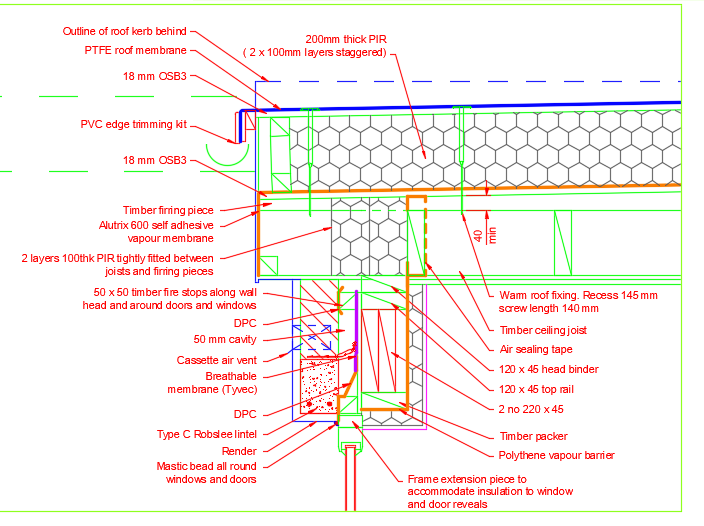
Hiya. I'll start with a general over view for folk on BH. Simplistically the warm roof works by keeping the structural members on the warm side of the insulation thus they are protected from condensation. On top of the structural joists we put a layer of say OSB and on top a good vapour barrier (Alutrix 600 is one) and that stops moist air from getting into the insulation layer, condensing and causing problems. This has many benefits in that we can run services and put in down lighters etc all on the warm side without having to seal stuff up against moisture. We can construct the walls by stopping moisisture from getting in and condensing in the wrong place.. we call this the dew point. Where the dew point is most likely to occur we can ventilate or similar. Say in a standard TF wall. @Sunil237 too right there is a cold bridge but also we need to control the vapour transfer at the transition between the wall and the warm roof. While it is technically posssible to mitigate by theoretical detailing ( drawing stuff) it is not buildable in real life unless you want to pay thousands extra.. no builder I know is interested and you probably can't afford it. Your Architect will duck this big time unless they are able to take a pragmatic view, recognise that there is no ideal solution and design something that is a good compromise and buildable at reasonable cost. I've shared the detail below for solid roof joists.. part of my IP property (yes it is mine as this is from basic maths design principles and also includes the rest of the structural behavoir) but what I can say is that every job is different. For pozi joists you could use a good air tight foam around the webs and flanges. Folks don't pinch it or you'll get into trouble but by all means use it to give you ideas. The detail below is based on pragmatic design, experience and knowledge of how each room in the house is going to be used and the structural design. The below will sort out the worst of the cold bridges but not all, it is buildable at reasonable cost. Hope this helps a bit and gives you ideas. The main thing is not to get too hung up on mitigating every cold bridge.. just do what you can and beef up the insulation levels where it is easy and cost effective to do so. The above should stop any really nasty cold bits which would result in say a line of mould on the wall or movement in the finishes due to significant moisture variations which can cause unsightly cracks in the internal painted walls and so on.
-
Top comment. One of the builders that I work with came round today and we were talking about not getting our own house finished. His wife has said to him.. if you don't pull your finger out then I'll do it. He said.. my wife is a better trades person than I and bloody handy on the tools! I need to finish it to avoid embaressment! (excuse the spelling) That's a good photo Nod showing the shrinkage crack adjacent to the stair and what a decoupling matt actually looks like.. it lets Buildhubbers see what can be expected without drama. Bit of tecky stuff for all. Very roughly screeds and concrete slabs that are cement based (even with additives) go through a journey after they are placed. In the first 24 to 48 hours they undergo what is called plastic shrinkage and this tails off after a bit. But this induces residual stress that does not go away. All the chemicals are interacting and bonding and this causes movement that we call this plastic shirinkage. Next you have drying shrinkage and this is the thing we are interested most in when doing UF and say tiling on top say. If it was my own house I would want to heat the slab up to the working temperature in the winter. While at the moment you may not see any cracks the slab could be in tension and a bit of extra heat will cause a sudden opening of a crack.. probably one you can't see from the plastic shrinkage. In my own mind if you just put a matt over the cracks you will just shift the movement elsewhere. Also the matt is quite thick so you'll need to make up the levels which could cost a fair bit on adhesive etc? Can you not just fit the kitchen and install the floor finishes later or do you you have free standing and mobile units? I never used to use a matt until I tried my luck on a suspended timber frame floor with UF between the joists and got stung! Big crack right up the middle of the public bathroom tiled floor.. that lined up with the bog pan.. it was the first thing you saw when you sat down for a "rest". At least it was my own self build.. but if that had been for a Client! In the past we used smaller tiles and they were a bit more forgiving. I have these large format ones in parts of my house. They are expensive and not easily replaced thus followed @nod advice. Yes a tiling matt is a heat barrier.. but as I have said before a lot of this stuff is about compromise.. we like rugs on the floor which insulate the UF.. pragmatism needs to prevail.
-
Party wall agreement when neighbour is AirBnB
Gus Potter replied to BonaVista's topic in Party Wall & Property Legal Issues
That is a good appoach keep things low key and friendly if you can. I'll make no further comment as no expert on PWA if you are in England. If in Scotland then I know a bit more. Will be interestng to see what other folk think.

