
PeterW
-
Posts
18480 -
Joined
-
Days Won
207
Everything posted by PeterW
-

Removal of Openreach equipment
PeterW replied to vivienz's topic in General Self Build & DIY Discussion
Write to them and give them 28 days to remove the kit. -
The issue with any of the frames is the twist on the frame rather than the crush effect by the pan. Ideally you need to double up the studs either side or as @nod said, ply the wall behind. Tile backer board tends to be cement based - you will not crush that or the plaster on the front of it as the compressive load is very low in reality.
-
Thanks - fits with my idea ..! Next question will be along shortly ... ?
-
Green screening for site boundary fence.
PeterW replied to epsilonGreedy's topic in General Self Build & DIY Discussion
Whatever the aesthetic issues, I would be installing Heras fencing as you need to make the site secure. -
Welcome ..!! nice plot, lovely views ..! Couple of observations on the plans .. that master ensuite is tiny ..! Why not spin the bed 90 degrees and bring the headboard back against the bathroom wall, and then extend the ensuite to the left ..? Would leave space for the chair next to the window and a view from the bed too..? Kitchen open to the stairs is a bit odd too - lots of space for a really nice hallway but seems very open so smells will travel upstairs. Other than that - looks great !
-
Making OSB air tight
PeterW replied to MikeSharp01's topic in Environmental Materials & Construction Methods
Installed with an expanding Polyurethane glue, OSB is air tight to well over the pressure used in air testing - make a box of offcuts and attach a hoover to it and you’ll see what I mean ..! -
Grand Designs Live Birmingham
PeterW replied to ultramods's topic in General Self Build & DIY Discussion
I will be there on the Thursday evening as it’s the late night - only time I can get. Anyone wants tickets let me know as I can register you as trade (I think ..!) -
@JSHarris I’m in your camp here ..!! Whilst I like the rPi, the thing I hate most is that if there is any power loss then I’ve got the potential for corrupt data whereas the Arduino just reboots itself and carries on... I’ve even rehashed the design on the IVT controller today dispensing with the thermistors and going 1-wire as I’ve got a load of them lying around the place ...! Out of interest, how did you mount the 4x20 display ..? I’m thinking a 2G faceplate with a CNC hole is the easiest.
-
IVT Ecolane ASHP - any owners out there?
PeterW replied to readiescards's topic in Air Source Heat Pumps (ASHP)
By way of update. The controller power works in reverse to what is expected : A5 - B1 +24v A1-A3 0v B2-B3 0v -
Help with kitchen renovation/ 1st house.
PeterW replied to zoothorn's topic in Bathrooms, Ensuites & Wetrooms
Before starting this - go buy some cheap baby wipes ..!!! Don't bother oiling the back edge. Clean it up with some sandpaper and get a tube of cheap clear silicone sealant. Good bead down the back of the board and push it tight against the wall and let the sealant squidge out everywhere. Screw the top from under the cabinet through the front rail then clean off the excess sealant with a scraper then go over it with baby wipes until all the excess is off. -
Help with kitchen renovation/ 1st house.
PeterW replied to zoothorn's topic in Bathrooms, Ensuites & Wetrooms
I would measure that upstand section and decide what you want it to look like. Have you got any worktop spare ..?? -
Help with kitchen renovation/ 1st house.
PeterW replied to zoothorn's topic in Bathrooms, Ensuites & Wetrooms
It will go over the top - only reason I sanded it was there were a few ripples in the width and I was making a couple of right angle joins so I wanted it perfectly flat. It also gives a fine finish as it’s had 120 and 360 grit across it on a DA sander so it’s smooth -
Help with kitchen renovation/ 1st house.
PeterW replied to zoothorn's topic in Bathrooms, Ensuites & Wetrooms
@zoothorn you need to oil the worktops when they are fitted BUT you need to fix them first with something waterproof. My go to glue for anything like this is Titebond - you can’t beat it for this sort of job. The bolts need you to rout a minimum 22mm depth groove and hole and you will have 8mm or less left - that will crack and shear and you will break it. I’ve just done 5 sections of this stuff with under mount sinks and 3 joins along both mitre joints and straight joints. I got it to 1/2mm or so and any filling was done using a mix of sanding dust and Titebond. (I have sanded these and refinished them using Osmo Top Oil for reference) All the joints are glued with Titebond, the straight joint was biscuit jointed. All joints are patched from below with 150mm glued and screwed ply panels. You can see a joint in the bottom left of this picture.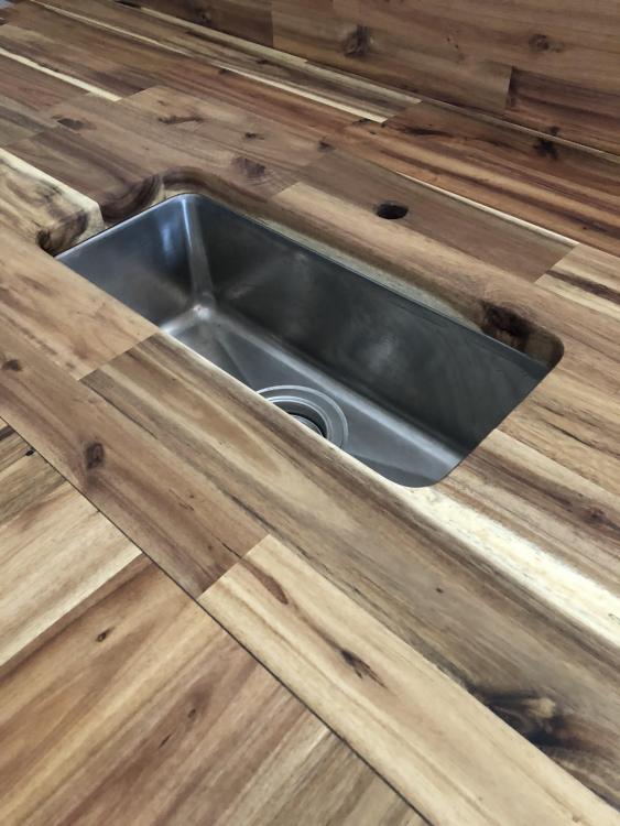
-
Help with kitchen renovation/ 1st house.
PeterW replied to zoothorn's topic in Bathrooms, Ensuites & Wetrooms
If that is the worktop from Homebase then don’t bother with bolts. If you want it to not move, sand the edges lightly to get rid of the oil and then mark the angle of the end of the unfixed portion - assume you know how to do this ..?? Trim the end and clean up to a perfect flat finish with the router and a clamped bar to give you the straight line. Mark and biscuit cut in both sides / ends to match. Cut a couple of plates of 12mm ply 150mm square and put a 30mm screw in each corner. Get some decent wood glue on the biscuits and the joint and push the joint tight. Now put glue on the plates and screw them on from underneath across the joint. May want to add a couple more screws once they are on. Damp cloth over the wood joint to wipe off excess glue and leave to dry. -
Thanks @MikeSharp01 - this will be pretty low frequency stuff that has long time constants - it’s about monitoring the state of pumps and valves that aren’t changing with high frequency.
-
Thanks both. Considering a relay thanks @Ed Davies and have now decided I may use this elsewhere too ..! Just annoyed I ran Cat5 everywhere but to where I want to sense now ..!
-
Right ... on top of a couple of other little projects, I’m building up my knowledge of how certain systems are operating. One thing I want to do is sense the on/off and state of a couple of valves and pumps, but that gets me into some questions. 1 - the 3 way valve has a microswitch, is there any issue in running 5v/GND through this directly...? Only query would be that the connections would be inside a wiring centre containing 230v 2 - would the quickest way to sense the pump running (ideally a logic 1/0 switch) to be to put an SSR in parallel with the pump..? Some of this may be a distance away from the Arduino so using I2C connected sensors is probably not an option. Thoughts..?
-
IVT Ecolane ASHP - any owners out there?
PeterW replied to readiescards's topic in Air Source Heat Pumps (ASHP)
Happy for you to post the pdf manual here as it will be interesting to see how you have interpreted what is a basic PID algorithm into the binary steps unless you have also implemented variable speed control into the pump also. -
IVT Ecolane ASHP - any owners out there?
PeterW replied to readiescards's topic in Air Source Heat Pumps (ASHP)
@Matjaz looking at your link that is an Arduino running a 20x4 display, 4 buttons and 3 thermistors. Adding a cheap PSU I would expect there is no more than £25 of parts in total in a unit that is priced at £350. To make a closed loop unit to only do the basics is a similar price. Your comment that using the 1-7 steps will result in significantly lower energy consumption is completely untrue ! To heat water to a temperature requires exactly the same amount of power at 50% as 100% as it just runs for twice as long .... @ProDave that is pretty much what I’ve done this morning - Pair of DS18S20 sensors on flow and return, a quick ramp up / down algorithm and then vary the power input as the DeltaT between flow and return reduces. -
I’m installing an induction hob that has a max capacity/current of 7.4kw / 32A on the manufacturers information. Sparky wants to run a 40A RCBO to start with and from memory it’s run in 6mm T&E from the board (need to check..!) It’s a mix of run in the open web joists, chased into walls, and run in a stud wall around the back of cabinets and around 12m in total. The cable terminates behind the stud where the hob is installed in a 40A isolator switch. From there it is less than a metre of flex to the hob. I’ve assumed that 4mm butyl flex would be fine here as it won’t get hot (hob base is max 40c) and it’s a very short run - but the 6-4 transition is niggling even though I know it should be fine ..! 6mm flex seems to be a bit like rocking horse poo so before I go searching for the holy grail, I’d just like to confirm the thinking ..!
-
Total energy consumption per m2 per annum
PeterW replied to NSS's topic in Energy Efficient & Sustainable Design Concepts
INet will transfer your BT number to VOIP. -
You may find pre-mix postmix is just as quick and cheap. Slit the bag and dump the dry content in, spray with the hose from time to time and job done as it sets really quick.
-
Parking outside our house: managing it sensitively.
PeterW replied to ToughButterCup's topic in General Construction Issues
Did you use that urinal they have on the side ...??? -
Help with kitchen renovation/ 1st house.
PeterW replied to zoothorn's topic in Bathrooms, Ensuites & Wetrooms
All he means is drill through the wall from behind it and connect to the terminals - the 2G socket remains in place inside. -
Help with kitchen renovation/ 1st house.
PeterW replied to zoothorn's topic in Bathrooms, Ensuites & Wetrooms
Going to need a picture as that doesn’t make sense ..!!