
BotusBuild
-
Posts
1379 -
Joined
-
Last visited
-
Days Won
10
Everything posted by BotusBuild
-
ICF was my choice - mainly DIY build with access for concrete pumps and lorries. Each floor took less than 2 weeks (if you ignore self imposed and imposed delays). Take into account who is doing the building, access to the site, how quick you want to get built, how much money you have to spend on trades (brickies, groundworkers etc) and how quickly you can get hold of trades people, especially in Cornwall! Good Luck
-
Using waste plasterboard as backfill
BotusBuild replied to BotusBuild's topic in General Self Build & DIY Discussion
Thank you all -
Thoughts? We have plenty of deep areas where we can put this that will not be used to grow anything or that will affect water courses or aquifers.
-
The humble but infuriating ....
BotusBuild replied to ToughButterCup's topic in General Self Build & DIY Discussion
Glad to be of service -
The humble but infuriating ....
BotusBuild replied to ToughButterCup's topic in General Self Build & DIY Discussion
Ratchet handle "closed". Have the slot which the strap goes through in the position you can see through it (may need to ratchet it round before closing the ratchet.) Feed the fly end, or the loose end, of the strap from the bottom of the slot up towards you - you should be able to see it coming through if the slot is lined up nicely as above. Pull the loose end through as much as you can to take up the slack. Holing the loose end hand tight, now start ratcheting. Tie off any spare strap
-
Need help worth a detail on my floor roof dormers.
BotusBuild replied to gavztheouch's topic in Flat Roofs
An alternative is to use GRP (fibreglass). Messy, but will mold round that batten nicely. You could go all the way along the join, making it one continuous seal. Thinking about it, this probably the better solution in this situation -
Need help worth a detail on my floor roof dormers.
BotusBuild replied to gavztheouch's topic in Flat Roofs
I think the sticky EPDM is the answer, but not in one piece. A piece over the batten first, which goes up the slope say 10-15 cm, and also across the flat board by the same amount. Then a piece that comes down the slope and overlaps the first piece. Where it gets to the batten, overlap as far as you can, probably only 3-4 cm, molding it round as best you can, getting it to stick as well as possible. Finally, slap some of our favourite sealant, CT1, across all the joins of both pieces. HTH -
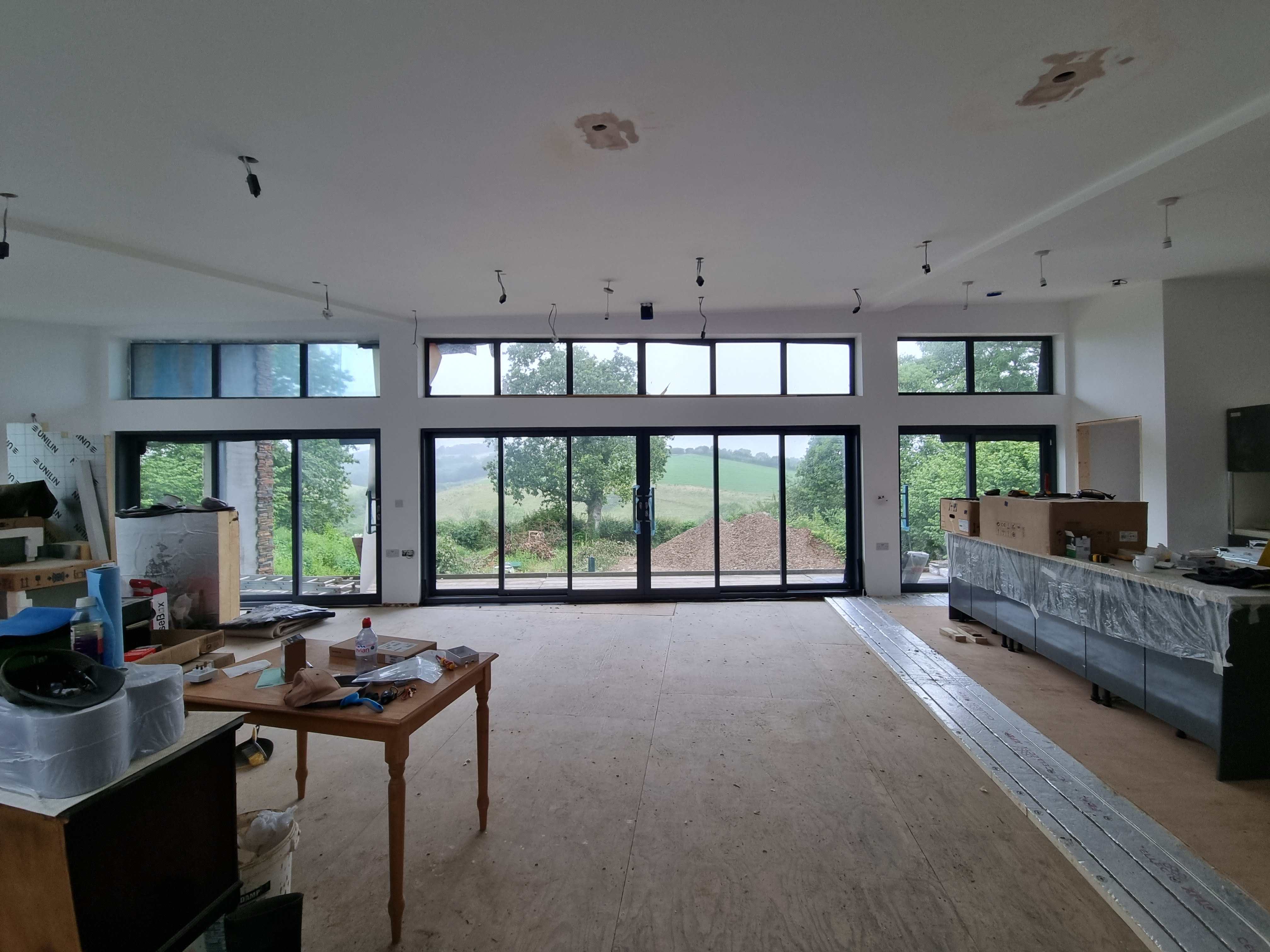
Sorry, this is not good news, so skip reading if you want. SWMBO worked at John Lewis as a specialist in the curtain and blind section. For any window that does not have 4 right angles i.e. is rectangular or a square, blinds or curtains are a bespoke design and make (handmade, and it's a skill). As a result of her experience we dumped the 9 windows that had a 9 degree slope at their top edges. Yes, just 9 degrees she was not prepared to work with! For the smallest gable end type windows, you'll be looking at £3K upwards. You may find a local curtain maker who could do something cheaper, but for blinds you have little choice of manufacturers who will entertain you.
-
We have Origin windows and sliding doors. They do not fit themselves, like many manufacturers. If you know who is going to fit the windows (hopefully not the builder!), then get the fitters to have a chat with the builder
-
Will be looking at this in addition to the acoustic rockwool (or similar) that will be between the joists. Do you know if standard plasterboard is sufficient? This is only for a single domestic building, not between flats or offices.
-
No, adding UFH to the upstairs living area in addition the ground floor UFH.
-
You mean just the UFH in the slab downstairs (bedrooms and bathrooms)? SWMBO will want those bedrooms cool. I'd like the living area upstairs comfortable 🤣
-
Corrected 🙂
-
Does anyone know if there is somewhere in the South West (we are in South East Cornwall(Kernow)) where we can see various UFH setups including floor buildups. It's time to decide which method before doing the upstairs open plan living area floors. We currently have 18mm ply on top of the Web joists with bathrooms and bedrooms below, so noise transfer plays an important part in the choice (not sure if one build up is better than the rest) TIA
-
Sand the scaffold boards and then use an oak stain?
-
Reclaimed scaffold board?
-
Replacing Hyundai Brush cutter. Is Stihl the only option.
BotusBuild replied to flanagaj's topic in Tools & Equipment
Just replaced a McCulloch with another one. Reason: last one was left out overnight and some vermin chewed a large hole in one corner of the fuel tank. Tried to repair as no replacement parts for that model were available -
To close off, planning permission was granted 2 days ago. A suitable drink was taken that evening 😁
-
We put in what looked like a 3 rung ladder, in a square area measuring 6m (ish), for about 30m of pipe in 1m trenches, so 30m2. All guided by local groundsman. I submitted photos and the BC came round to check the coverage of the pipes with stone. Site in England
-
Never diagnosed, but much evidence exists that supposes I do have it. Thank you.
-
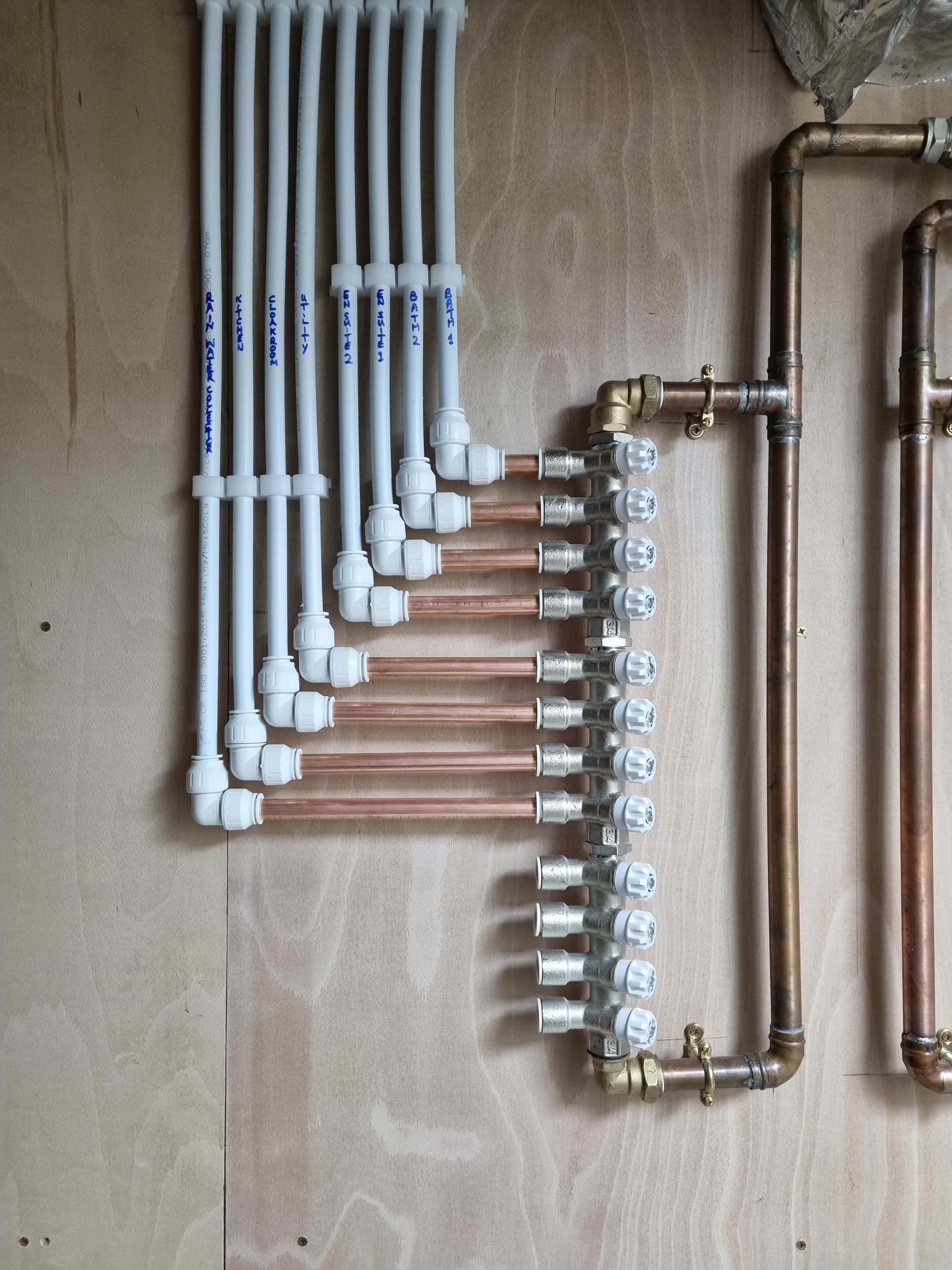
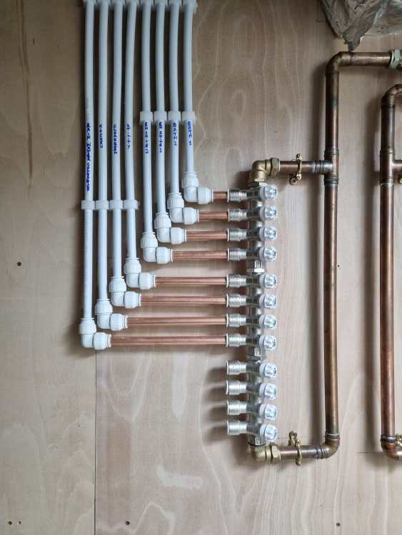
Finished connections to cold water manifold yesterday (last job of the week). Think I should put stop ends on the ones on the future proofing slots? (Rhetorical)
-
Are brick slips dearer? Let's see!
BotusBuild replied to John Keith's topic in Insulated Concrete Formwork (ICF)
Fair enough. This seems different to everything else I've absorbed on the topic. Let us know how you get on - i hope it goes well. For my stone slips I think I'll stick to having what is recommended by Nudura. -
Are brick slips dearer? Let's see!
BotusBuild replied to John Keith's topic in Insulated Concrete Formwork (ICF)
Are you certain about this? Everything I have read (I'm also doing Nudura but with stone slips) is that you need to have a scratch coat render applied first -
Thank you @dpmiller, that seemed the logical way.
-
And before you ask, there are no instructions in the box