
Ed Davies
-
Posts
1674 -
Joined
-
Last visited
-
Days Won
1
Everything posted by Ed Davies
-
Practice may be slightly different but probably not much different: in theory the cooling COP should be one less than the heating COP because the energy in the electricity going into the pump contributes to the heating but not to the cooling. I = thermal energy going into the heat pump (from outside when heating, from the house when cooling). What matters when cooling. O = thermal energy coming out of the heat pump (to the house when heating, to the outside when cooling). What matters when heating. E = electrical energy going into the heat pump. Assuming no other losses then O = I + E. Cooling COP = I/E. Heating COP = O/E = (I + E)/E = I/E + E/E = I/E + 1 = cooling COP + 1.
-

Help with kitchen renovation/ 1st house.
Ed Davies replied to zoothorn's topic in Bathrooms, Ensuites & Wetrooms
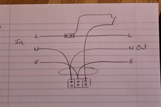
Seems you're sorted, good. But for clarity: 1) We're talking about the switched live/line here. Not the permanent live with the loop in/out and the live to the switch which is also in the ceiling rose in the way lights are often wired in the UK but is likely on a separate connector block up in the ceiling in your case. 2) Yes, as I first posted that comment I didn't say to connect anything else to it but spotted I'd missed that on proofreading immediately after posting and added, a couple of minutes later, that the live to the light should be connected as well. (It took a few minutes as I drafted some grumbles about that DIY doctor page then decided they'd only likely cause confusion therefore it'd be better not to post them.) -
Help with kitchen renovation/ 1st house.
Ed Davies replied to zoothorn's topic in Bathrooms, Ensuites & Wetrooms
You could keep the terminal block or use the standard ceiling rose connections as convenient. Assuming you don't keep the terminal block, the wiring colours in your existing connections are not completely mad and going clockwise from lower left in the diagram on this page for reference: https://www.diydoctor.org.uk/projects/ceilingrose.htm Neutral terminal: your two black wires and also the neutral down to the light (blue). Earth terminal: your two yellow/green sleeved wires plus any earth wire to the light if it needs it (i.e., if it has exposed metal bits - instructions will say if it needs an earth and it'll have an appropriate cable supplied with it). Switched terminal (“live” in that diagram or “line” in more modern terminology): your red wire and the line (brown) to the light. Live terminal: leave unconnected as that's not directly needed by the light and its function is presumably done by a terminal block up in the ceiling (the one @ProDave suggested you go digging for). I.e., standard wiring except you needn't bother with the line connections and your switched line is actually red rather than the more common black in that age wiring. -
https://www.britishhelicopterassociation.org/simple-guide-for-setting-up-an-unlicensed-helicopter-site/ Would presumably also apply to fixed wing: I think that's how farmers operate off their own strips as many days of the year as they like. Nothing metaphorically or literally under the radar. It'd be when they let anybody else use the site that the change-of-use clock would start counting up to 28 days.
-
My understanding is that using a bit of your own ground as a private strip for your personal use isn't a planning issue at all, in the same way that parking your car on your own land doesn't require change of use to a car park. Even having friends drop by for a cup of tea in their aeroplanes is no different in principle from friends arriving by car. It's only when there's some sort of arrangement with third parties that it begins to matter. Friends had a private strip that they flew their aeroplanes off with no hassle at all. He used to do a twenty minute aerobatic practice flight before starting work in the morning. Only when he started, with others, an aerobatic team and would be going off to commercial airshows and his team mates would be arriving for practice, etc, did they worry about planning permission. It was amusing that people nearby objected that having aircraft coming and going would be terrible but they hadn't even noticed that the strip had already been used for a couple of years.
-
Pity Quinetic don't do this function anyway as (AIUI) their switches just generate some sort of pulse signal when they transition. That ought to be able to (re-)trigger a timer. Maybe they do?
-
There are a few business called CarbonLite around the world. Probably not a direct trademark issue but maybe difficult with search engines and the like. Talked to them very early on in my project development (when I was still looking at another site) about them doing a large bit of my house. Got on well and quite interested both ways but I wasn't sure about the cost of their method of construction. Went back to them later, when I was struggling a bit with the post and beam stuff, to see if they were interested in making me a kit but they were very busy with a large project by then.
-
Possibly confusion rather than made up as such: 1 tog [¹] is a thermal resistance of 0.1 m²·K/W so a thermal conductance (“U-value”) of 10 W/m²·K. Maybe that was what was on the manufacturer's brochure/catalogue/data sheet. Since that's about the thermal resistance/conductance of the slab/air interface anyway it would be reasonable to think of a 1 tog carpet as doubling the required slab/air temperature difference, a 2 tog carpet as tripling it, etc. [¹] lower case, it's just the name of the unit (slightly humorous, as in getting “togged up”) , not an initialism.
-
Carbon Dynamic? Were they CarbonLite in a past life or something? Matt S?
-
… and careful not to touch any of those components below and left in that picture (GDT, MOV1 and neighbours like D5) as some are likely to have mains voltage on them. They're for protection against spikes on the power line, etc.
-
Can you see the part number on that heat-sunk device ProDave suggested putting a meter on the bolt of? Might have to unplug J22 to look at it. I'm thinking it's likely a 7812 voltage regulator or some modern equivalent. If it's a 7812 then the tab will be grounded so measuring the voltage on the bolt won't help much. If it's an LM317 or similar then the tab and bolt will be at the output voltage so a bit more interesting.
-
OK, weird that's by the power supply stuff when all the other i/o is on the other side of the board.
-
The orange and black wires on the plug in J22 (between the fuse and the heatsunk device) - where do they go? To 23 and 24 on the lower connector block to the right? Does the book say what they are? General purpose 12V supply? Worth checking? Too long a string of suppositions?
-
It's called conformal coating. If you need to scrape it off to make measurements then you can get bottles or spray cans of the stuff to replace it. Better not to get it on connectors, though.
-
Me too. Good advice I was given by somebody who'd done a lot of lifting in various jobs (engineering for a water company and storeman in a furniture factory), and done his back in a few times in the process, was don't lift and twist, lift then twist. I'm also a bit bad with the bend ze knees protocol but don't have too much trouble so long as I'm straight on to whatever I'm lifting.
-
Triassic didn't say that, only that they edited a document they had read access to. If you can read a document (either one which is not password protected or one you know the password for) then you can, if you have the right software, produce an edited version of it. Obviously.
-
@JSHarris, thanks, yes, had seen that (and thanks also for the blog link) but not at all suited to my use-case for reasons I won't derail this thread with but might be worth discussing separately.
-
3D model render submitted in planning application?
Ed Davies replied to Moonshine's topic in Planning Permission
My formal drawings for planning were produced by the house designer in AutoCAD. Still, I included a 3D sketch (made in SketchUp) in the design statement (which I wrote and the house designer checked). Did it help or hinder? Don't know but the application was approved as quickly and as painlessly as these things can be so it can't have done too much harm. SketchUp needs a bit of a learning effort but I've found it worthwhile. My first serious use was to “reverse engineer” the structural engineer's 2D drawings into 3D to make sure I really understood what was going on with some details. Building up the drawing (switching on layers) in the order it would actually be built helped with making sure there weren't any serious mistakes in my planned sequence as it would have been easy to snooker myself with some aspects of the roof/floor join (not being able to install some fixings if other bits had been put on first). Since then I've used SketchUp a few times to work out dimensions of things working back from “as-built” dimensions and generally for get confidence that things measured one way will really line up with things built another. -
I'm with @JSHarris on this; the mechanical mounting considerations and source of the control signal are more important than any pros/cons of relays vs SSRs for an application like this where switching is not going to happen more than a few times a day. If it was likely to be switching more quickly (e.g., multiple small immersions being switched on and off to approximately follow the changing output of PV as I have in mind) then SSRs would be preferable.
-
That doesn't necessarily mean much. Here's a horrible extension lead thingy from amazon.de. You can ignore most of JW's droning on here, the bit near the beginning about it not carrying the CPC (earth) wire through from the input to the output 3-pin sockets is damning enough.
-
Help with kitchen renovation/ 1st house.
Ed Davies replied to zoothorn's topic in Bathrooms, Ensuites & Wetrooms
Is it possible there was a second switch for this light at some time in the past? -
I've a £99 Lidl generator. Supposedly 1200W. Dunno but runs my 500 or 600 W sanders, etc, just fine. Haven't really kept track but probably done between 10 and 20 hours so far. I've also got a 1200 1500W, 12V inverter which I run off my van batteries. That needs the van engine ticking over, though, which was fine when I just needed it for 10 minutes at a time to do some drilling (using a 230V drill in a drill stand) but didn't feel right when I was doing more extended sanding.
-
Thanks JSH and Peter, had long thought of making something similar myself (for PV diversion into big thermal store) but it'd be a lot better to use an off-the-shelf version now I know they exist (knew about the Willis thermosyphon for solar thermal but for some reason hadn't come across the electric version until recently).
-
BTW, do these Willis heaters, and the like, use standard immersions as fitted to cylinders?
-
Help with kitchen renovation/ 1st house.
Ed Davies replied to zoothorn's topic in Bathrooms, Ensuites & Wetrooms
First guess, which needs verifying/contradicting, would be that it's something like this. So, yes, there's probably at least one other terminal block stuffed up in the ceiling somewhere.