


le-cerveau
-
Posts
524 -
Joined
-
Last visited
Everything posted by le-cerveau
-
 You can get High Temperature ASHP, Daikin do one, this is a 2 stage device, the water is heated by a conventional ASHP, this is then raised by a second indoor stage to up to 80oC, the downside being you cannot set it up for cooling! The original SunAmp Stack used to be specified with this. Not sure how efficient they are at High Temp though.
 -
My plant room is upstairs, 2 x MVHR, ASHP (internal unit), boiler, 4 x SunAmp, 3-Phase switchboard... However I have solid concrete floors (pr-estressed planks + screed) and a lift!
-
My PCM34 cells are effectively an ASHP buffer, they are charged by my ASHP up to 45oC, the ASHP shuts down at about 42 when the SA unit stops calling for heat. They are used as the the UFH buffer and also DHW pre-heat. The PCM58 cells then provide the DHW.
-
I don't have UniQ's but rather an interim (pre UniQ) dual port (UniQ technology) units, 2 x PCM34 and 2 x PCM58. There is no casing bulging issue but the cases are remarkably solid. I don't have internal heaters (I wasn't available) so control is rather simple, when cool (what level I don't know but suspect 50%) they call for heat. apart from an initial issue which was resolved (custom controls) I haven't had any issues with them. They are effectivly 2 x UniQ Heat6/9 (PCM34) and 2 s UniQ HW 6/9 (PCM58).
-
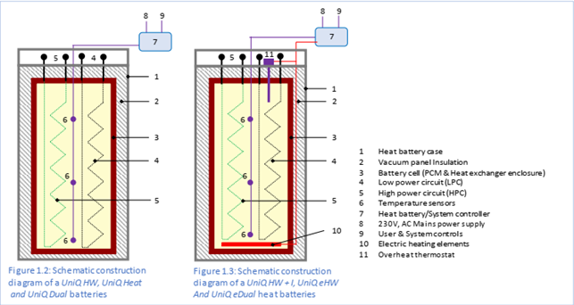
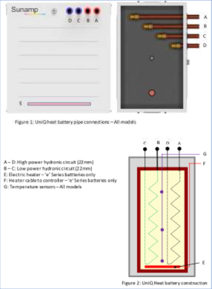
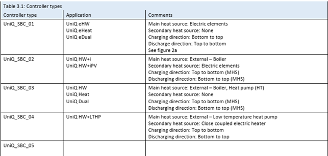
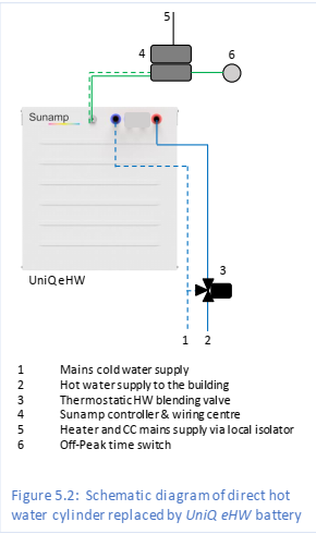
I am shooting from the hip but I suspect that there are basically only two UniQ (physical) models! Agree this should now be a separate thread. They come in five (5) sizes (3, 6, 9, 12, 60) and 3 PCM fillings (34, 58, 73). The two models are with and without the electric heating elements, the Heat 60 is not available with heating elements I believe. Not all combinations are available, the PCM 34 & 73 are not available in size 3 or with heating elements. So, for an example if we take a size 9 in standard PCM 58 there is: UniQ HW 9, UniQ Heat 9, UniQ Dual 9, UniQ HW 9 + I, UniQ eHW 9, UniQ eDual 9 The first 3 don’t have a heater and the second 3 do, so two physical models. I make this assumption for the following reason, design and cost, it is cheaper and simpler to have a fewer physical designs and make changes in software. As detailed in section 1.1 of the design and instillation manual. The only difference is 45mm in height (for all sizes) the electric heater element and it’s connections. The plumbing connections are the same for all models, it is just how you connect them that differs: From section 1 of the reference manual V2.0: A = High Power feeding the top of the heat exchanger. B = Low Power feeding the top of the heat exchanger. C = Low Power feeding the bottom of the heat exchanger. D = High Power feeding the bottom of the heat exchanger. High Power is typically used for the potable water and Low Power for primary Water. The order A – D varies throughout the reference manual! I will stick with this demonination. Controller details from section 3.1 of the reference manual: (there is inconsistency between the two manuals) For all but the e__ units they are designed for an external heat source, so charging direction is top to bottom, therefore Heat source flow goes to B and return to C. Potable water (DCW) feed to D and (DHW) to house to A. This is all detailed in the reference manual and also in the design and install manual. This is what I would consider normal, you pump heat into the top of the cell/tank with the return at the bottom and you feed in cold water to the bottom of the tank an d take out the hot water from the top. For an e___ unit there is confusion, the reference manual shows paralleling the HP and LP circuits (makes sense as all potable) but feeding the cold water into the top of the heat exchanger and taking the hot water out of the bottom, whereas the design and install manual does not parallel the circuits (omission) but does feed the cold water into the bottom and take the HW from the top, so again inconsistencies. I suspect this is down to the thoughts in the previous table that normal units are heated top to bottom but that the e__ units are heated bottom to top (because of the heater element), however that heat will migrate to the top of the tank so it should still be discharged bottom to top (flow) as per normal. The so-what is if you have a standard unit (NO e or I) then it can be used as any HW/Heat/Dual functionality, if you have an e or I unit it can operate as any unit an e only unit a normal unit, just ignore the heater or an I unit, it is just plumbing and wiring. So in theory (at least anyway) Jeremy can wire up his unit as a HW+iPV unit using the correct controller and it should accept charge anytime! It is all just a controller issue. Ready to be shot down in flames!
- 186 replies
-
- 1
-

-
- sunamp
- energy efficiency
- (and 1 more)
-
From the UniQ manual posted here by somebody else. I just read through all the options. It appears that the system is capable of of doing what is wanted jut not configured by SunAmp in the appropriate manner. SunAmp should have an eHW+iPV model that is plumbed as an e__ model but controlled as a +i__ model. Ideally it should have 3 mains feeds, one permanent supply, one PV shunt and an economy 7/10 threshold take power from the normal supply. Ideally it would have more sensors than the 3 at the moment (10) so you could select each of the thresholds on setup. SunAmp could offer the units as standard or advanced, with the advanced having more sensors and control options for a small premium. Surely that is just an power limit, if you have more power the UniQ just won't accept it/you diverter channels it elsewhere. Again a control issue.
-
@JSHarris, I have been pondering your issue for a while and think I know the issue. It is a differing of understanding between you and SunAmp. Your system is purely electrical and designed for PV input (only), which worked well with the original SunAmp. The UniQ systems have 3 options: The UniQ e___ series designed only for electric input. The UniQ ___ series designed only for external heat source input. The UniQ ___ + i__ series which takes both. The UniQ eHW/eHeat/eDual is designed for permanent connection to power and will recharge when 90%/50 depleted. The UniQ HW/Heat/Dual is designed for an external heat source (boiler/HT ASHP/…) and will signal for recharge at 50%/90% depletion. The UniQ HW +i/HW +iPV has both and will signal for the external heat source at 50%/90% depletion, but accept PV charge whenever it is available (what you want). You have an eHW but want eHW+iPV control so that it will always accept PV charge when available but could also accept mains charge when reaching 50%/90% depeletion. The problem being that the eHW charges/discharges in the opposite direction to the other units. You could potentially wire up as an eHW+iPV with mains on the control circuit and PV on the power diverter circuit, then when the control circuit is at 50%/90% depleted the control circuit could switch a mains relay changing from PV diversion to mains power (not enough PV to charge) and charge from the mains. Hopefully it would never reach this level of depletion. You would probably need the UniQ_SBC_02 controllers (suspect you can’t reprogram yours different connectors) and have to plumb the units up the other way round (flow/return). This problem is I suspect a lack of understanding from SunAMp on how units are being deployed, PV reinforcement the system should work perfectly, but for PV only the programming is wrong.
-
MVHR Duct Design
le-cerveau replied to Triassic's topic in Mechanical Ventilation with Heat Recovery (MVHR)
I originally looked at a single large unit and they are available, the issue is the 250mm connections, going to the outside with that size and then splitting it into 2 and then into your plenums, you will need 2 plenums each for supply and extract for a house that size, I have a pair for downstairs and a pair for upstairs. The issue at running these units at these speeds is noise and efficiency. At full tilt they do make noise that will then be transmitted through the ducts to some extent, and if you look at the details they are far more efficient (heat exchange) at around 50-60%. PassiveHaus specifications don't allow them to run at those speeds, a PH certified unit has a lower PH capacity that it's absolute capacity. My Brink Renovent 400's run at 140 and 175 m3/h respectively, they are capable of 400 m3/h but as you go above 200m3/h they start to become audible. -
MVHR Duct Design
le-cerveau replied to Triassic's topic in Mechanical Ventilation with Heat Recovery (MVHR)
I had a similar problem, 472m2 floor area, which gives an extract rate of 131.37 l/s or 472.92 m3/h. I have 2 x MVHR units both running well below max as this reduces noise and increases heat exchange efficiency. My system was designed (by myself) at 495 m3/h to comply with building regs but I run it at about 316 m3/h and that more than copes with the house and is probably still quite high. My system auto boosts back up to the higher rate or even high 570m3/h based on the RH sensors in the extract ducts and these work well detecting shower usage. Layout I used the Ubbink system with 180mm rigid ducting between MVHR units and the outside/plenum boxes and 90/75mm (Outside/Inside) semi rigid elswhere. The kitchen has two extract terminals each with two ducts, everywhere else I used single ducts to terminals, though wet rooms have two extract terminals and bedrooms two supply terminals. This was to keep velocities down. The whole system is silent though you can hear the MVHR units in the plant room when at the Building Regs speed, but at the normal running speed nothing. -
Mine are configured as low temp and high temp, effectively a Thermal Store without the losses. Even if you just used a PCM54 unit it is equivalent to over 100L of water do I really put a DHW tank in each bathroom (5), downstairs WC, laundry and kitchen. I would then have to run primary pipes to each unit to heat them (mine are not electric). I would also size each one for each room, so two capable of filling a bath and/or shower, three more shower only. A central point allows for diversity, I can assume not all outlets in use at once, distributed need full capacity at each outlet. They are also not cheap. If you have electric ones, how do you decide which get the solar divert first?
-
No, I am a SunAMp man with central storage, 4 units, SunAmp is not designed as a point of use system but as a replacement for cylinders.
-
I specced all pipes to be lagged (overkill). I have long DHW runs with a circulation system so lagging to keep down losses, and there's nothing worse than warm cold water!
-
Comfort cooling MVHR
le-cerveau replied to AliG's topic in Mechanical Ventilation with Heat Recovery (MVHR)
Ours have only been in just over a year and if you check online they are still available and in the 2018/2019 catalogue. -
Comfort cooling MVHR
le-cerveau replied to AliG's topic in Mechanical Ventilation with Heat Recovery (MVHR)
We have internorm windows with internal blinds on all windows, the room doesn't have to be dark to keep out the solar gain, you angle the blinds to block the sun but light still gets through, you don't black out the room just tilt the blinds. They are very effective, so much so that you remember to drop and tilt them to keep out the excessive glare, and consequently solar gain. You can even program them to do it automatically based on the sun! I have not yet bothered with this. -
Comfort cooling MVHR
le-cerveau replied to AliG's topic in Mechanical Ventilation with Heat Recovery (MVHR)
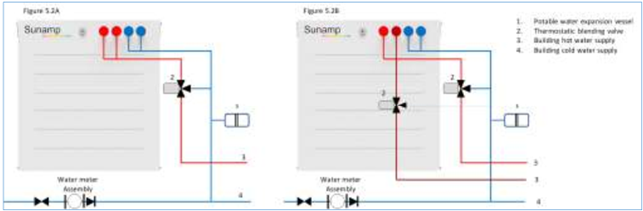
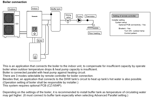
My ASHP will allow it (though mine isn't wired up for it yet). Two diagrams form the service manual showing how to do it. On the first one the 3-way valve is for the ASHP to set Heating/DHW. Mine is rigged for heating/cooling using 2 x pre-UniQ SunAMp PCM34 units as the Heating buffer and DHW pre-heat. I am considering as re-plumb/wire as the ASHP has been running for up to 8 hours a day to re-heat the units, It only takes a 2-3 hours if there is no concurrent heating demand otherwise it runs until the heating demand is satisfied (pushing about 34oC the PCM temperature), then quite quickly climbs to the 44oC cut off. The units require 45oC but stop the call at about 43oC. This re-heat is elongated if my mother has a shower (not short) as this also depletes the PCM34 units. SO I may consider plumbing the boiler heating circuit into the PCM34 units, currently it only supplies the PCM58 units with 65oC water.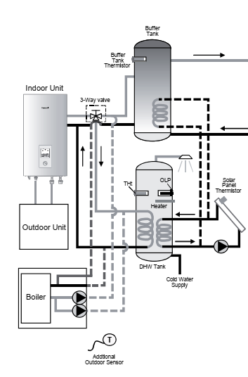
-
SE is looking at a simple structural method (easier for him) to reduce complexity. The SE is simply there to do the calculations based on your requirements, and advise if not possible and alternatives, not shape your whole build. Depending on the size and shape of your house, plot conditions, location, local environment, some methods will be more beneficial than others. We went ICF, because a) we wanted a solid economical house but more importantly I had 12m spans that could only be done with precast slabs, which limited the options. Managed to get the spans down to 8m (max practical) with a single steel and post without affecting the plan. That was done my my AT (Architectural Technical) not an SE. My AT employed SE's where required for specific jobs.
-
One of the main reasons I went 3-phase is that as a Passive type build we have an all electric kitchen, with 2 x 7.2kW induction hobs (Split level for wheelchair), 3 ovens drawing 3.7, 3.1 & 2.9 kW (worst case) add in 9kW for the ASHP (though the most I have seen it draw is around 4kW (recent cold)) then the standard single phase supply is at risk of tripping if you get it wrong. I have also put in a 3-phase spur into the garage for a future car charger.
-
The wire is bigger as it has 4/5 cores, instead of the usual 2/3 cores, but the cores will be similar size. Most domestic electronics is 230v single phase. We have 3-phase in our house but only 2 x 3-phase devices, the ASHP and lift, though both were available in single phase versions. Yes you need specific 3-phase capable equipment as the harmonics between the 3 -phases have to be synchronised. We have nearly 10kW of PV on the roof, but it is connected by enphase microinverters that can be connected 1/3-phase, ours are evenly distributed across the 3-phases buy the installation equipment (3-phase wire where each microinverter sequentially connected to the next phase). Yes, but the cost will vary depending on your situation, we had 3-phase directly in front of the house and we were simply spurred of the main line, the previous supply was simply one of those phases.
-
Is our winter generation amount about right?
le-cerveau replied to MikeGrahamT21's topic in Photovoltaics (PV)
The peak is the maximum at any given point in kW so max power at a given point the 945Wh is power generated over a 15 minute period. It is the way enphase reports. -
Is our winter generation amount about right?
le-cerveau replied to MikeGrahamT21's topic in Photovoltaics (PV)
So far today we have peaked at 3.78kW / 945Wh and already produced 13.5 kWh, however if I go back to Saturday it was peak 0.28kW / 71 Wh total for the day 0.94 kWh. Not teh worsk 15 December 0.56kWh, compared to 22 June 18 70.2 kWh!!! Over 100 fold variation. My array is just under 10kW split SE/SW. -
Floor plan — comments welcome
le-cerveau replied to Dreadnaught's topic in New House & Self Build Design
I won't quote aesthetics but practicality of deeper windows. We only have two in the house I finished and they work, let in a lot of light, but they are in a huge room >100m2 (kitchen/lounge/diner) and don't dominate the room. In our house in Latvia, where they have an obsession with them, they eat up wall space. The lounge wall is rendered useless because of them, you can't put anything against it and in the bedrooms again you are limited to where you can put a chest of drawers, because of them. In yous design I would consider do you need them in the bedrooms, have you planned out all the furniture. The lounge one not such a problem as it is a walkway. -
Floorplan - Any thoughts/suggestions?
le-cerveau replied to Coops85's topic in New House & Self Build Design
The en-suites i put in my kids rooms were 1.8m wide by 2m and you can easily fit everything in. Put them back to back and it simplifies the services. You could put it between bed 2 & 3 -
Only if you cross connect between equipment.
-
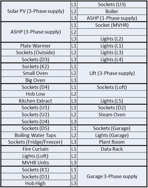
I have 3-phase installed at the house. We have an 18 way unit in the plant room, that is 18 x 3-phase ways or 54 x single phase ways and there are only 5 spare single phase slots left!! Everything is spread out on its own circuit with RCBO for all (except the fridge/freezer circuit). This is the layout: The Garage 3-phase supply is for future use (car charging) and is a 32A supply to support whatever come along. I need to get the electrician to do some swapping of circuits/phases as L1 is lightly loaded and L2 and L3 have a heavier load, my induction hobs can draw 7.2kW each, in preparation for future battery systems (when prices drop to the appropriate level).
-
Heating system for an ICF house with UFH
le-cerveau replied to Nelliekins's topic in Other Heating Systems
Don't know about the coil however as as you cylinder is primary water, you can just take the UFH direct from the tank. There is no need for a buffer as that is to reduce short cycling is a boiler/ASHP but you already effectively have one, your tank is effectively a TS as it is primary water not potable. How are you going to cool the UFH, where will the cold water come from? With your buffer, you would just raise everything to the same temperature and delay the temperature raise but not cool it, you need to inject 'cold water' at some point. This is usually via an ASHP, unless you intend to just run mains cold water (water bill) through it?
