RobLe
-
Posts
232 -
Joined
-
Last visited
Everything posted by RobLe
-
What is considered to be short cycling
RobLe replied to Johnnyt's topic in Boilers & Hot Water Tanks
For a heatpump thats considered just ok, 3x an hour. The restarts shock the system, fatigue the brazed joints, reduce its life. -
How about heated chair covers? 100W at 12V into a strap on seat cover, intended as a retrofit for a car, makes a huge difference. Uses a lot less power than a radiant thing heating the world.
-
I think with the symmetric scheme where each batt has a CT with 2 wires through it in order to negate the other battery current flow, and a 2kW kettle turns on, then: Batt1 will provide 2kW Batt2 will provide 2kW So yes, the kettle will be powered by the batteries. But then the main tail will export 2kW, surely not wanted?
-
I think the mutual nulling you suggested will: Make PW supply the same power the house uses, and at the same time Make SE supply the same power the house uses That's too much power, that's why I don't like it! I think it will provide 2x the required power. The cables are unlikely to fit through the CTs, as an aside. I would love any/all schemes to be tried though, out of interest!
-
Why do you suggest to do this? I'm with OVO, they pay 3% interest on any balance, so why not stay in credit? We've been with them for 10 years, the DD bounces up and down as their "algorithm" tries to figure out what we will use over the year, I just let them "manage" it.
-
@Radian: Agree syncing charging is part of the issue, but it alone wouldn't be terrible. The dominant thing is an underconstrained system, where it is completely valid for PW to charge SE and the other way around. Hence the horrific up/down spikes in power in the top graph above from the op.
-
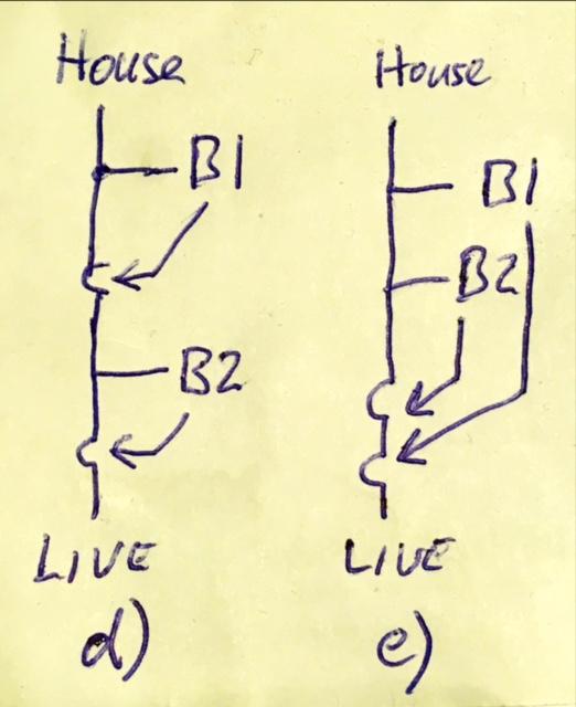
If the PW and SE are wired in series, as (d) above, I think that they both will work. When the sun shines, PW will gobble it up assuming PW=B1 in (d). It's not a voltage thing, it's just where it's CT is positioned that matters. When the kettle is on, the PW will provide. When there is too much sun, the PW will be full and stop taking power.... then the SE will fill up. If the PW were to fully empty, then the SE would get a chance to power something. It might not be quite as above, as the PW can also be controlled by Tesla(?) - I think Tesla might tell it to power the grid sometimes and pay you for it - eg via Octopus "Tesla Tariff". This could screw up if so, as SE will immediately thwart that behaviour, absorbing that power. You might be better off with SE on the inner loop, so PW can discharge into the grid if you want that to actually work(don't bother if you don't want this!). You'll also need to make sure any night battery charging times are synchronised between PW and SE. Eg if PW charges in the middle of the night from the grid, but SE isn't programmed to do that, then SE will charge PW, which is inefficient. By and large though I think d) is good..
-
It's not my house, so I don't know for sure how it's installed... a piccy of the CTs would help - I think they will be on the same wire, and I would be willing to bet money that it is actually installed like (e) below. That is, each batt connects to the house consumer unit or a henley block next to the consumer unit. Then each batt CT connects to the tail (the order of the CTs here makes no difference). And wiring it like this is the cause of the issue, even though each battery may be individually wired as it's install manual - I'm guessing they haven't considered anybody would be ambitious enough to have 2 batteries. In contrast, I think that (d) will fix the issue completely. I'm not changing my mind, it's the same schematic as (c) I did a while back, and also the blurb I wrote some time back. It is clear to me, although I'm having trouble convincing the internet!
-
You don't need to worry about the voltages - the PW and SE will do all of that complicated stuff with their power electronics and control algorithms. All you need to know is that the PW is trying to minimise the power flow through its CT; it will put out whatever current at whatever voltage is required to achieve this. Imagine that you sublet a room in your house, where you had a single power feed in, and there was a PW battery, and a kettle which somebody turned on and off, maybe even a bit of PV. The PW battery would effectively power the kettle. You might not even know that they had done this, inside their sublet room. Then imagine you fitted an SE battery to your whole house - this would work too, but nothing it does will affect the PW operation.
-
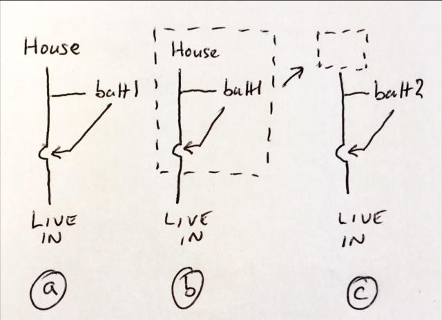
I'm going to have another go at convincing people 🙂 The pic below is in 3 parts, showing a progression of the idea in my mind, and without pesky equations: a) is as the manufacturer intends, batt1 having a CT on the tail before it, so that it can identify the power flow and try to make it zero on average. It's doing a lot of maths and clever power electronics to achieve this, but we don't need to know about that. A bit of power sneaks in and out on transients, but otherwise it does a good job. b) is just like (a), but I've put a dashed box around the house+batt, and now we are just going to ignore what's inside - it all just works in isolation - any interactions are inside that box, and ultimately just give or take power from the grid. Importantly, nothing from outside the box affects the inside (neglecting stuff like the grid is broken etc). c) now we apply another battery, but you can see that box from (b) replaces what was just "house" in (a). So batt2 should work, just as well as batt1 in (a). As described before, the 2nd batt won't do much work - the first will preferentially absorb PV and make the tea, 2nd batt only operating when the 1st for some reason cannot. 🙂
-
That's a very interesting arrangement, but I'm not sure that will do what you want. As an aside, you may find it difficult to fit 2 thick cables through the clamps. Anyway - considering the power into B1, B2, and House - I think the schematic above, with knowledge that B1 is trying to null CT1, will create 2 equations: B1=-House B2=-House Thus the overall power from the Live Tail will be the sum of B1, B2, and House: B1+B2+House = -House. The units will each independently compensate the house, but that's unlikely to be what you want, as you've gone too far and are still interacting with the grid. In contrast, the version I intended a while back gives equations: B1=-House B2=-House - B1 Thus the overall power from the Live Tail will be: B1+B2+House = -House-House-B1+House = -House-House+House+House = 0 No current at the tail, just what we want I think 🙂 Honest.
-
So both PW and SE are home batts, and there's no useful software settings on them to prevent interaction? I think the issue is that the combined system is underconstrained. PW presumably has a current clamp on the main Live tail, and is attempting to make the current there zero, using a software feedback loop with likely a PI(proportional + Integral) controller. SE is presumably the same. While you might think they would both sit there doing a similar thing - slowly feeding on PV say, an equally valid solution is for one to discharge into the other, while still overall feeding on PV. I think if the PW clamp were after PW+House+PV, then SE clamp after PW+House+PV+SE that this stops the PW responding to the SE as it can't "see" that current flow. The SE can still respond to the PW - but the overall feedback loop is broken, so I think this might fix it 🙂 One of the home batts will be exercised much more than the other doing this - the way around I described it, the PW will do all of the work until it cannot, being full or empty or having too high power flow, then the SE will mop up the rest. Disclaimer: I'm just a diy-er with ideas above my station 🙂
-
A friend of mine had I think a similar, but simpler problem. He had V2H and also a solic 200 diverter. With no sun, the solic should do nothing, and V2H supply the house. What actually happened is that the solic sometimes turned on and ‘stole’ all the V2H energy, everything ramping up to full power. The solic and the V2H had slightly different ideas about what the power flow into the house was, causing the issue. We fixed it by bodging 10 thin turns of wire around the solic sensor in addition to the mains tail, with 100mA ac flowing in it from an (mains)ac-(selv)ac adapter, convincing the solic that there was 1A*240V less available power than reality! The above fix only works because the solic takes power only, and (obviously!) can’t deliver electrical power. Perhaps you could see if either the PW or SE(another home batt i assume) have adjustable dead band regions? That is, if one of the units allowed power flow in either direction of less than 100W or so, then the issue might resolve. The bodge we did will not work for you, if both units can have bidirectional powerflow; you need a software fix, or a more complex bodge.
-
Ooooo maths! If it's a cube of insulation, each side of size X (metres), with a U-value called Y(W/m^2/degC), full of water DT(degC) above surroundings(it makes the maths easy, and you'll not do better than water): Area = 6.X^2 Losses = 6.X^2.Y.DT/1000 (kW) Volume = X^3 Energy storage = DT.X^3 (kWh) - just so happens that 1T of water stores 1kWh/degC 🙂 So the time constant = energy / losses = DT.X^3 * 1000 / (6.X^2 . Y . DT) = 180 X / Y (in hours) Lets say Y = 0.1W/m^2/degC, so the time constant = 1800X. So if X is 2metres, using a U of 0.1, we can get to 3600hours, a time constant of around 5 months - just enough. If we have water in it. Sand won't be quite as good I think. Agree with last post .... it needs to be big!
-
Great work! Could do with 2 of them to the same cpu - we have a main meter and a PV meter. I think we might need another meter again really, in series with the main one but backwards, to measure power flow both ways. Then we have V2G....Why is it so complicated?! Some elec meters have isolated outputs, as well as an led, that pulse. This one that I've used does, pulsing at 1 pulse per Wh - prob worth getting that sort if you're buying one. I used a 10k pullup resistor to 3.3V, connected -ve to cpu 0V, and fed the pulse signal into a cpu input: https://www.amazon.co.uk/Electric-Electricity-Backlight-Certified-Calibrated/dp/B096YBRRYK/ref=sr_1_7?crid=3VCCVWXIONQEG&keywords=electricity+meter+din+pulse&qid=1657462762&sprefix=electricity+meter+din+puls%2Caps%2C106&sr=8-7
-
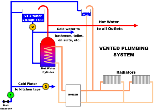
We have a vented DHW system, pic of similar attached. The tank is nicely insulated, it's even boxed in with poly beads down the back! It occurs to me though that the vent itself is a horrible heat leak mechanism, as it leaves the hottest part of the tank, then travels upwards into the cooler loft. Sure that pipe is insulated, but not as well as the tank, and that whole 2m length of that 22mm copper pipe thermosyphons away so is permanently at the maximum DHW temperature. Is there any reason why there can't be a thermosyphon break (london loop, short down then up segment)? I've looked in the regs, and they require that the vent be 19mm ID minimum, but there's nothing I can see about it having an upwards only slope. Every picture I have even seen on the internet shows the vent heading straight up, or horiz then up (hardly any better). It just seems a huge waste of heat to install that way. Thoughts ?
-
Ebay do £10 solar controllers, that claim to be mppt. They are not, but work fine, just at lower effectiveness. For more money you get real mppt from victron or renogy(£70). Real mppt will allow a higher PV voltage, and will optimise for it, the cheapie ones demand a ‘12v ready’ panel. This time of year we get an average over 10kWh/day from our 4kWp solar. So a 100W panel, on average, could give over 10W, in summer, so long as your battery was big enough to ride through a day of rain(a 1kWh car batt is loads). Totally agree to go bigger than that, 200W, and cheapie controller: https://www.ebay.co.uk/itm/134114306097?hash=item1f39d5e831:g:X8sAAOSw2nZiY9VV
-
Is it possible for PV diverting the opposite way round
RobLe replied to Gone West's topic in Photovoltaics (PV)
It is a strange thing to want to do. PV diverters normally have a current clamp around the mains feed, and optimise for zero power flow average in that cable. If you could (get a sparky) fit live PV and live immersion through the clamp(same way through), then all PV production will be sent to the immersion, until it is full. If your lucky the wires will reach, they will fit ok as they’ll be thinner than the main tail. Have to say, I wouldn’t advise it, I expect on average it will not replace as much grid elec as a normal diverter install, so will cost more. Diverters are mostly about saving money not co2, as elec/oil/gas are largely similar carbon intensity. -
In order of preference: Insulate the DHW tank, check if there are are there forever hot pipes "thermosyphoning" your heat away? shorter showers:-) PV + diverter Octopus Go / E7 AROstor or similar tank with inbuilt heatpump
-
We should have installed air conditioning… now what?
RobLe replied to Adsibob's topic in Other Heating Systems
PV on the roof cuts down the heat getting in, if you haven’t got already? 2nd the external blinds. Not that we have, but I’m sure they’d be effective. -
MVHR - Self install!?
RobLe replied to richo106's topic in Mechanical Ventilation with Heat Recovery (MVHR)
We diy'ed our MVHR, I'd definitely do that again. It's a very fiddly and bespoke process - for a pro or an amateur I think. We ended up with rectangular plastic pipes neatly at the back of existing built in cupboards, round metal pipes in the loft. The unit is in the loft, on the wall. Most of our pipes are 150mm, one long loft run is 200mm, ducts are 150mm. Big pipes => slow airspeed => quiet and efficient! Or many smaller pipes, I'm sure that's good too. I recommend humidity and CO2 sensors, let it control based on these rather than a user (=wrong most of the time) - I think some units now come with, ours (VA Sentinel+BH) had humidity inbuilt and 0-10V analogue inputs that I added a CO2 sensor to later. -
I don’t think that 3m is a hard and fast rule. Our neighbour has been advised by his architect (and paid for plans) that he can build over his shared sewer for a length of no more than 6m. The neighbour is ‘upstream’ of us, there’s just 2 properties above him. He hasn’t got pp yet mind, so this may not be right! His drawings show a staggered extension, part beyond the sewer, part constrained by it, with foundations running alongside and within 1m of the sewer. There are a lot of problems with our sewer, the area is quite flat so it doesn’t slope much. I’m not aware of problems in the 6m stretch in question. We’re in Cambridge.
-
Additional electricity load on home with GSHP
RobLe replied to 8Coops8's topic in Consumer Units, RCDs, MCBOs
Perhaps you could consider EWI, to get that 33MWh/year heat load reduced, whatever the heatsource. While the cost difference between a small gas or oil boiler to a high power one isn't that great - that difference will be very significant for a gshp, and also (to a lesser extent) with an ashp. Have you had a quote or estimate for the gshp? I would expect the price saving from a 15kW gshp down to a 5kW heatpump will cover most of the cost of EWI, and the ongoing elec bills will be much smaller too. GSHP often have simple (more reliable but perhaps not quite as efficient) on/off compressors, I think mainly as there's less of an issue with external audible startup noise than there is with an ashp. None of the above is a reason not to get three phase by the way, get it if you can. -
@JohnMo You're entirely right, it is for that reason. I found a ref to the same fact in a book that I've borrowed on heatpumps. Annoyingly despite being a 400+ page book on heatpumps it didn't go into any more detail than that, so I'm left to speculate, and maybe you know more which would be great! I made my own heatpump that has been running fine for 6 months with no heater (don't think I'm an expert, all just diy).... ahhh - a bit of googling before posting works wonders - there's a wiki article on it, I think says we're both right "crankcase heater": "A crankcase heater is an electrical component in a compressor in an air-conditioning system, heat pump system, or chiller system. The crankcase heater is normally on all the time, even when the unit is not running, though temperature sensors and set points may turn it off when not needed. A crankcase heater's sole purpose is to prevent refrigerant migration and mixing with crankcase oil when the unit is off, and to prevent condensation of refrigerant in the crankcase of a compressor. The crankcase heater keeps refrigerant at a temperature higher than the coldest part of the system."
-
Our VA sentinel kinetic plus bh averages at 100m3/hour. When we’re in it’s more, when we’re out it’s less, it goes up and down based on humidity and CO2. The filters get changed every 3 or 4 months - that’s when it starts nagging. I pull out the old filters, take the fabric off the metal frame, clip on a new bit of fabric with ‘supaclip’ clips. Piccy of an old one about to be changed: