Carrerahill
-
Posts
2132 -
Joined
-
Last visited
-
Days Won
10
Everything posted by Carrerahill
-
Real World SIPs Experiences
Carrerahill replied to LA3222's topic in Structural Insulated Panels (SIPs)
That is not a SIP. A SIP is just OSB/Insulation/OSB. They have connecting "spines" on them and they just push together like jigsaw pieces, no studs. The detail above to me looks like a fairly standard timber frame construction with foam injected between the studs rather than PIR foam cut and installed. A SIP is just a panel construction, these can just be bought as 8x4 panels and you can work them yourself to your build, or a SIP kit company will buy in SIPs and make them relevant to your build or indeed make the SIPs onsite themselves. You can make SIPS at home if you can be bothered. -
Real World SIPs Experiences
Carrerahill replied to LA3222's topic in Structural Insulated Panels (SIPs)
It wasn't a build of my own, or a project I was directly involved in but one I followed fairly closely via colleagues who were providing engineering services to a site that used SIPs (they had nothing to do with the design or SIP's at all I hasten to add). But on that project I heard 'nightmare', 'never again', and 'why didn't they just let us build this this with 2x6' was being banded about on site every day and the framers who were erecting it hated every minute of it. The general summary was that SIPs have basically no tolerances for even small onsite variations and issues and can lead to some fairly lengthy processes being carried out to make a panel fit after shaving bits or cutting bits and making new joining spines and hot wire cutting the insulation or trying to cut and slice bits out. -
Out of a matter of interest, why did Building Control screw up? Whoever detailed, or possibly didn't, this aspect of the build screwed up - BC are only there to ensure they are happy with details and designs and that contractors build appropriately to those details and designs. Whoever was responsible for the structural design and detailing of this structural aspect, i.e. your architects SE, or independently appointed SE - remember architects just draw pretty pictures, engineers make buildings possible - or your architect forgot to bring this to the SE's attention.
-
Is it a cavity wall? Why are there not two steels one each supporting one side of the wall? I am sitting in my office just now and my structural engineer is 6 feet from me. He is laughing - sorry... I suggested and he has confirmed: In this situation it would be more common to have two steels, sitting at the required spacing to hold the wall and then put spacers pieces in-between which could be as simple as some M20 threaded rod and nuts either side of each I beam or RBS with some flanges welded to each end and drilled for bolts. The welding on site can also create issues with the strength of the plate as the weld will be right along the stress point of the plate - bolt it. Alternatively re-spec the I beams as wide flange and get a flange that suits the size.
-
I would not be asking about the price but why this has come about first of all - has someone put the steels in the wrong place, can you show us a photo of the steels in place as they currently are. The wall is 325mm wide - OK what is it made up of, what does it do, why does it need to be 325mm wide etc. etc. are all things I would want to know. I can get you a quote for the 2 pieces of plate easily enough if that helps you. As for the welding it depends what is required - it may not need welded, in fact I would probably prefer it was bolted if being done on site which changes things again...
-
If the drain hole is in the right place, and you are going to tile it, then I cannot see why it cannot work - you may need to think out of the box a little but if you were to go for a low profile slot drain, and tile up to it with a fall to the drain from each side then it should be fine. I don't know what drain pipe is in place but assuming 40-50mm then you could get a low profile drain unit (look at units designed for use with UFH as they tend to have a smaller footprint), you may at worst need to disc cut out a 300mm square around the drain pipe so you can bed a deeper drain back into the concrete but I see no major issues here. If it was me - I would go to my friendly fabricator and have them make me a stainless steel tray with relevant stub to push into the drain pipe and buy an off the shelf slot drain etc. or have them create a simple SS slot that I can tile up to. People who say things like this are not possible like this are just lacking in problem solving skills or imagination. In the case of Topp's Tile's it just because he doesn't have a product that will suit your application.
-
2.5m wide garage door, a decent default size?
Carrerahill replied to epsilonGreedy's topic in Garages & Workshops
Sounds like we both had the same ideas and for the same reason. A green oval product! -
Just looking for some images or help regards the door opening detail for my timber kit extension - our build is a little odd as we already have a sun room in this part which will form part of the new extension, so I am reusing the door opening. At the moment it leaks down the outer skin into the cavity, but that is because the builders who built this have used a piece of ordinary concrete slab along the top of the block wall that the door sill sits on, however, they then laid slabs up to the same height as the door sill, so water must just pour down the gap between the slab and door sill, and flood in under the sill over the piece of concrete slab and into the extension! They were clearly cowboys or got their levels all wrong and didn't want to resolve it - the bead of silicone along the slab to and sill shows that someone did see this as an issue! So, in my new extension the door will end up moving in slightly as it will sit flush on treated 50x50 around the opening in the timber kit then the block work will come up to the edge of the frame and get rendered in. I am going to be modifying the suspended timber floor at the weekend and want to prepare the door opening at floor level during this time - can anyone show through images or details they may have how I do this. This is my plan, for now, based on best practise: Install a concrete sill on top of the outer wall, assume no DPC under it so it can drain, I may possibly pour this in situ with a run to exterior and higher than the slabs obviously. I will order a door with a stub sill and this will sit on the concrete sill and end up sealed in. Around the door the render will come up close then get rendered or I will use a render strip and seal it all. So externally there should be no route for water to get in, and any seepage under heavy rain or someone hosing the door or something daft would only result in some water possibly getting in behind the render, down the frame and into the cavity, even at ground level water should not not in as it will run off the sill. Internally I will bring the floor up to the inside of the door frame, this will bring it to the edge of the inside of the cavity, where the door frame will then start. This means there is no bridging except for the door frame itself but sitting on it's own stub sill and then the concrete sill all water will run away from the door - I will also reset the slabs outside the door which are at the top of some stairs with a very slight run away from the house - at present they run in the way and thus under the sill! Does that make sense and sound right? I know it is such a simple detail but only if you have seen/built one before do you know your install is deemed common practise and not just my best practise guess!
-
2.5m wide garage door, a decent default size?
Carrerahill replied to epsilonGreedy's topic in Garages & Workshops
That should be pretty good, I sized mine to 2.6m wide by 2.2mm tall which should let me get pretty much anything I could ever want to fit in there. As decent width gives you the option of how to drive the car into the garage depending on how you may wish to use the space i.e. you can take a diagonal line in and maximise working space in the garage - another thing to consider if to bias your door to one side, I would have biased mine to be fairly tight to the left so it was parking only on that size, but tree's I didn't want to disturb meant this was not possible, albeit my door is biased left so the car doesn't sit in the middle and waste space down each side. I worked out my sizes with some of our cars and bits of wood propped up so I could actually work out what would be a nice size. -
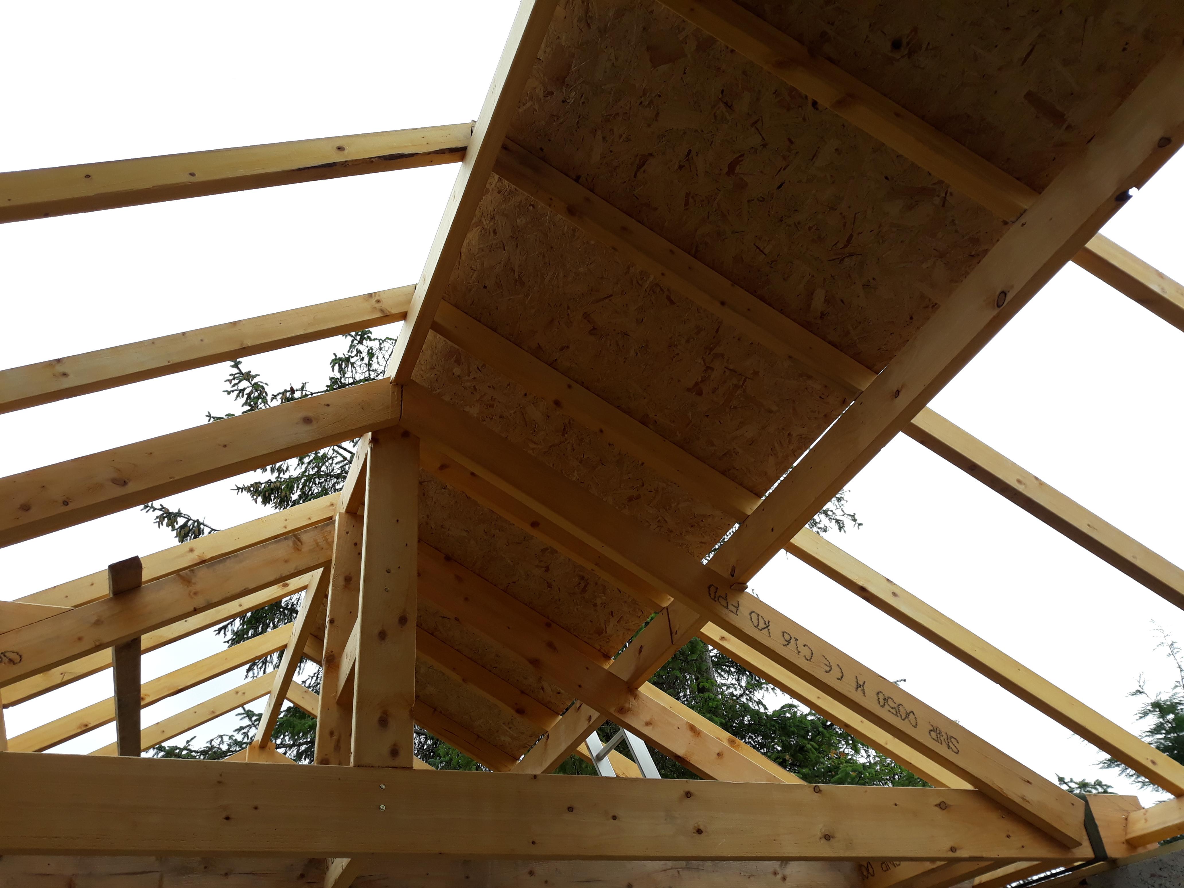
Cut roof design doc for building control.
Carrerahill replied to epsilonGreedy's topic in Roofing, Tiling & Slating
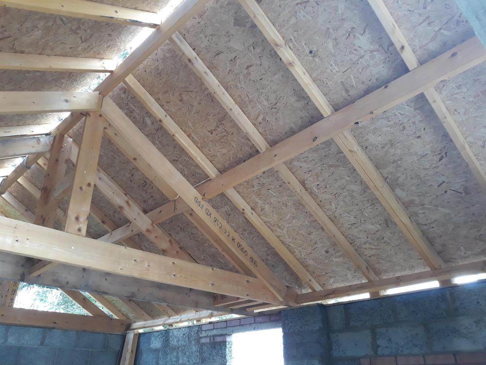
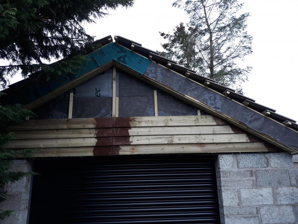
On my BW drawings there was just a written description of the roof's construction and a simple layout showing truss and purlin locations. Roof Construction: King Post Trusses: 200x50 C16 for joist span with 150x50 C16 rafters with king post made up of 2 No. 150x50 spiked together. 4 No. trusses in total spaced as drawing. Purlins sat on trusses, trusses notched to seat purlin. Rafters 100x50 sat on ridge, purlin and wall plate. Rafters to be notched. Rafters 600mm on centres. I have a truss above each gable end, then I have 2 trusses tied together with 6x2's 750mm apart, this centre truss arrangement is centred in the middle of the garage and the purlins run from the gable truss to the centre truss nearest it, the purlins run wild through the 750mm span where they just touch but are not joined in anyway. This creates a very robust roof with lots of open space as there are technically only 2 "joists" at wall plate height the rest is totally open. I have 420 concrete tiles up there and when I was up doing the ridge tiles I had a little jump and the whole thing is solid as a rock! -
What type of boarding above rafters
Carrerahill replied to Moonshine's topic in Roofing, Tiling & Slating
But then again, builders in the central belt of Scotland can't even put walls up properly so that doesn't really say anything... -
Extension floor thoughts.
Carrerahill replied to Carrerahill's topic in House Extensions & Conservatories
Been thinking a lot about this today, to the extent I have hardly done any work! I am tempted to go for one of the timber options - question is... which one. My thinking is if I go for option 2 but I wonder if this is seen as a bit of a bodge, albeit it I could construct it very carefully and make sure it's sturdy. -
Neither did I until last year, then looking at my building warrant drawings I saw "40mm insulated plasterboard" - I thought this was just poorly written and meant some insulation then PB - but no, they make it right up to about 150mm I think! So that is what I am doing my ceiling with. https://www.roofingsuperstore.co.uk/product/celotex-pl4025-insulated-plasterboard-1-2m-x-2-4m-37-5mm.html?gclid=CjwKCAiA4t_iBRApEiwAn-vt-2Se-YUgDUcezZG-USHSv1-qocyATnDPBL_jlSLNG0f6SJfaNEc3ChoCyngQAvD_BwE
-
Unusual P2P case
Carrerahill replied to Jeremy Harris's topic in P2P lending, Crowd Funding and Alternate Sources
Having been involved in a loan before for someone we instructed a solicitor to draw up a "contract" it was loose in as much as neither of us even really felt it necessary we just created it and filed it, end of. It was just a safety net, it didn't even stipulate payment terms or anything just a very broad form of protection. So it was written, signed, witnessed etc. I cannot remember the full details of it, it was over a decade ago, but it was more of a security that if something happened to the person the money was lent to, their estate would accept there was a liability to me there was also something that said the loan had to be repaid within 3 years and at that I then had the ability to take them to court if they didn't meet this obligation, the period was more like 1 year, so we picked 3 to give a very comfy buffer. I think a small legal firm would charge £250 for something like that and just add it to the final sum (which you must also agree on the legal document). EDIT: Just realised someone resurrected an old post... sigh. -
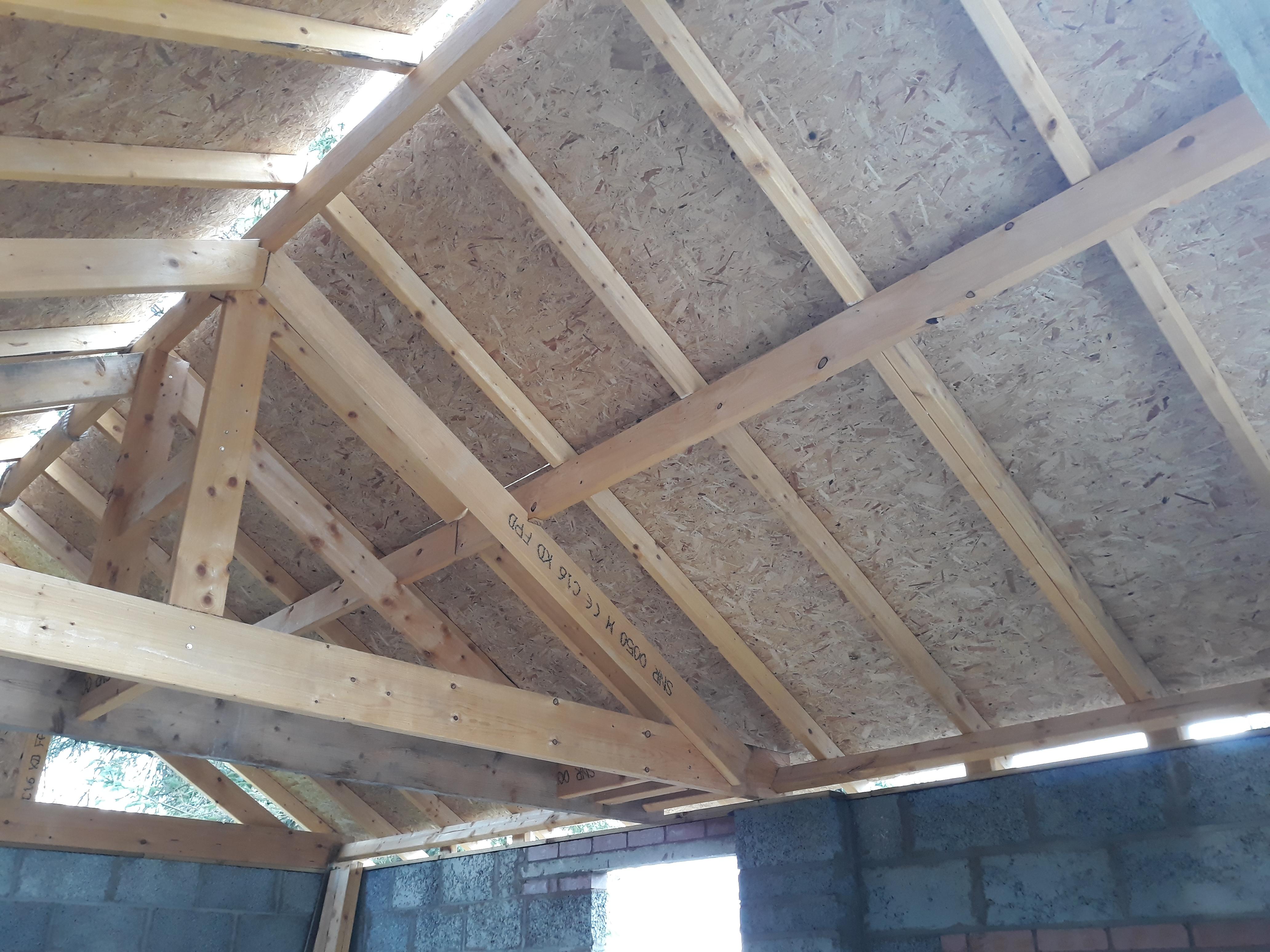
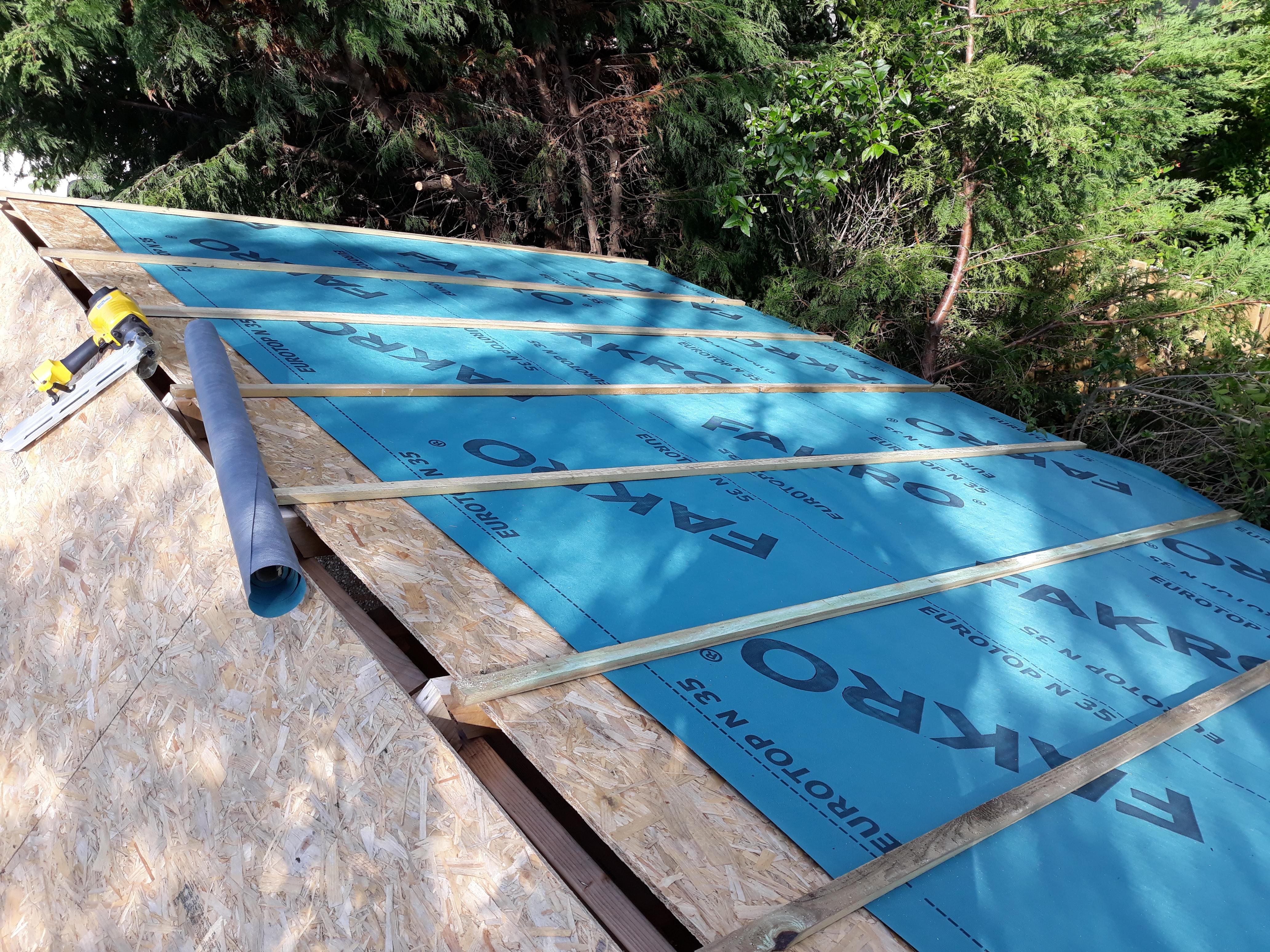
What type of boarding above rafters
Carrerahill replied to Moonshine's topic in Roofing, Tiling & Slating
What you are looking for is standard practice in Scotland, I have never seen a roof in Scotland without boarding (sarking) on it, well once by a major house builder building cheaply. This is just my garage and it's fully boarded!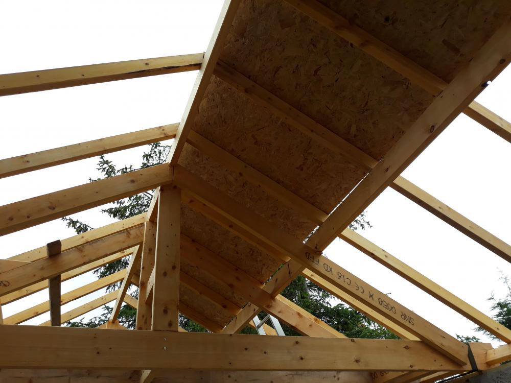

-
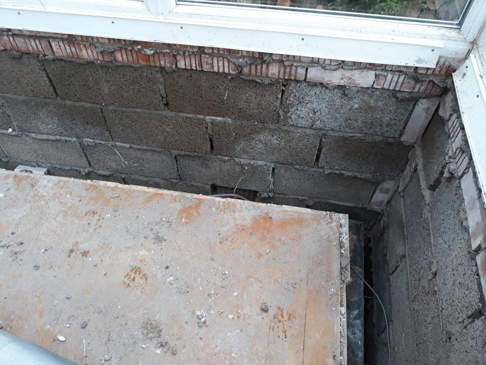
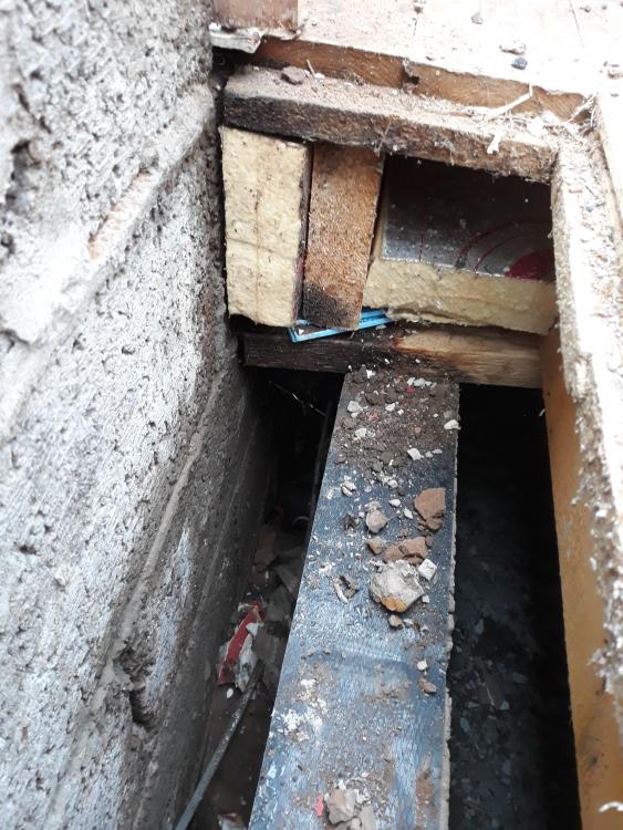
I have been working on the prep works for the extension over the past few weekends, yesterday saw the biggest development in edging me closer to the construction stage. Basically I have an existing sunroom which will form part of the extension, to prepare the area for the build I had to demolish the inner block-work to enable to me re-jig things ready for the build. Long story short I am now down to DPM on the inner wall which equates to about 220mm below floor level - what I have now is a room with a suspended timber floor with a 200mm gap around the perimeter, 100mm cavity and 100mm was the block - see here: Let's try not to pay too much attention to the soaking poor blockwork, the rotten timber that is soaked from the door threshold not being correctly constructed and water pouring down the blocks etc. So from this you can see where we are, the bottom photo is showing the long side of the sunroom and you can see the joists run long span across it and out of frame is a knee wall which supports the floor joists half way. So I need to get this all ready for a timber frame, so I started thinking last night and I have come up with some ideas. So a brief description of where we are right now: We have on the short sides of the sunroom a 215mm wide wall up to DPC, (i.e. block built 215mm face down)100mm of the joists bearing on this, a knee wall in the middle, also 215mm wide, joists full bearing on this, and then as per the bottom photo, a joist runs parallel to the block wall. I need to build a 5x2 timber frame kit onto this, leaving a 50mm cavity between timber frame and blockwork. Here are my options: Option 1: Lift the floor (I need to lift some of it anyway to get under and do plumbing) and lay longer joists so that they extend to within 50mm of the block wall, that leaves me my 50mm cavity to the end walls and then on the long wall where the joists run parallel simply nail blocking out sitting on the the wall and nail a joist to the end of these spaced 50mm from the block wall, I can use some brackets to make sure it is solid as the full joist will be hanging over the wall held only by the blocking, however, the timer kit will partially bear on the blocking which is bearing on a wall, so I see no issue. I can then run 5x2 round the perimeter of the room to act as my sill plate for the timber kit to be built upon. There are already battens attached to the bottom inside edges of the joists with 50/60mm Celotex in-between them, so with the floor deck off I can clip UFH pipes to this and biscuit screed the floor to top of joist, then lay whatever I need to lay on top of this to take a tile or maybe hardwood floor, ply/OSB over joists, or just normal 18mm caber? This gets me to where I need to be, ready to build a timber frame! Option 2: Leave the floor as it is more or less (still need to lift some of it to do plumbing) and attach a 6x2 to the top of all the walls, so about 100mm would bear on top of the wall on the DPC and about 50mm would overhang the wall into the cavity reducing my cavity to 50mm, then I can nail a 5x2 on as a perimeter piece but step it in 11mm so the OSB sheet can go on top and leave my 50mm cavity. So the timer kit is basically built off the wall. I can then do my UFH within the joists as described above. Option 3: Remove the whole floor, reduce the height of the inner walls by a block or 2 and put in a beam and block floor, Robslee have done a design for me, I can sit the beams out to within 50mm of the wall for my cavity, the blocks would rest on a pad at the long wall wedge so I basically end up with a block and beam floor 50mm from the outer walls all all the way round and hard up against the existing house wall with a little piece of insulation. I then would lay blocks on there side to form a 215mm sill round the 3 external walls, put down 50mm insulation, UFH pipes and a 60-75mm screed. The blocks around the external walls would just be to contain the screed, I could then attach a 5x2 sill plate to the block and I could even bring the screed up to the top of the sill plate (I would also use insulation to insulate the block to stop cold bridging. All these options would work, I do like option 1 and 3 the best but I had not really budgeted for option 3, option 1 and 2 only really require some more lengths of 6x2 for joists (which I have in the garage I think) and I could probably have the floor sorted ready for the kit by Saturday night (not including the UFH stuff) which lets me start getting the sill plate down and get some "site" measurements for my timber kit. The downside to option 3 is the weight, looking at the spec from Robslee and working out roughly what the screed would way I reckon it's another 4 tonnes minimum - OK this is spread across the 3 short walls and one whole edge of the floor would be spread the length of the long wall I am just being cautious. There is possibly another option - Option 4: The suspended floor has, from what I can see so far and measure a 650mm void below it - there is concrete over site on a DPM. Do I take all the blocks I have from the wall demo, and place them into the void, backfill with hardcore and sand and then DPM it again, insulate it all and pour concrete over site again but this time up to floor level? From the garage build and the demo works I reckon I have enough block and rubble and hardcore left over. Also bear in mind that whatever I choose I really want to be rolling with these works again at the weekend so I need to bottom out details ASAP. I also have a baby due in 6 weeks so speed is a major factor here.
-
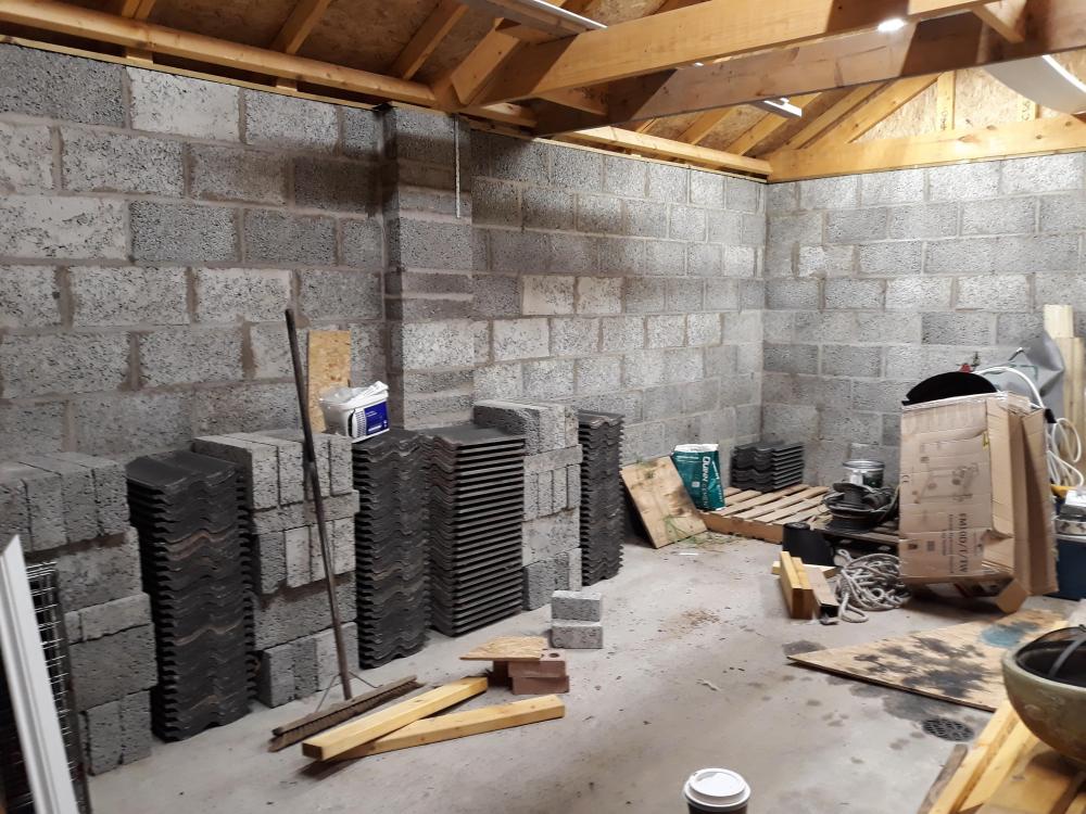
Land Rover(s) possibly an old tractor one day and a visiting MG-TC when/if it comes to stay for weekends. Could you tell from the oil soaked board there was something old and leaky in there! Protecting the concrete is something I need to address before the concrete get's totally stained. I am going to get a few gallons of concrete sealer/hardener stuff - then I can make up my mind - to paint, or not to paint!
-
I got my quote in for my windows and I spoke to the supplier, who is also an installer and he confirmed the 50x50 strap method - however, he can supply the windows with pre-fitted insulated firestops which I may just go for. I will need to confirm the detail with him but assuming it will fit then that will do. I think I am going to get the window with a stub sill and then build a concrete sill up under the window when it comes to block-work - I am going to sit down with CAD and carefully work ou my sizes so I am full courses to the underside!
-
Here are a few update pictures, I know we all prefer pictures!
-
Managing build myself, all advice welcome
Carrerahill replied to Wagas's topic in Project & Site Management
Being a Project Manager/Clerk of Works for a build can be good way to save some money and potentially ensure a high quality build, however it depends on your background and or aptitude to research and clearly understand building processes and details - so on the flip side, it could cost you. Although you will never know every detail of every part of a build if you have good construction knowledge one way or another (say you are a General builder, architect or consultant engineer) you then stand a good chance to act when you see things being done incorrectly - however, little or no knowledge and experience in the industry can lead to issues going undetected. That is not to say you couldn't educate yourself, to a point, but it depends who "educates" you. Plenty of contractors out there talk utter rubbish. I had a concrete contractor stand and talk drivel at me and also quote an eye watering price for concrete. Had the price been about right and had I been unaware of many things concrete related I may have gone for it... what I would have ended up with would have needed to be broken out and redone! The worrying thing is, a totally untrained man in a van can claim to be a ground-worker, turn up in a van, place concrete for our builds, possibly poorly, then our entire build sits on this for the rest of it's days! As for quotes, 20 quotes is excessive. As an example, I got 3 concrete quotes and 2 bricklayer quotes, I was able to raid the QS's folder at my firm and get pricing details, historical quotes etc. and I also generally know what I should be paying for a cube of C30-40 concrete etc. I also know what contractor day rates should be so when I was quoted nearly double from one chap I was able to ask him for his breakdown right there on the spot and trip him up horrifically as it worked out he wanted to be on about £1200 a day for himself - my laughter upset him a little! I even had the Tarmac rep in here, I liked his price actually - so don't discount getting the concrete yourself for your builder to place - it also lets you guarantee you are getting the concrete type/spec you order. -
Ouch!
-
OK I am listening... let's see if I have interpreted what you are saying correctly. I would install the window into the timber frame... That then keeps it in the "warmer" side of things, then I have to firestop/cavity close between the frame and the block, but what do I do about rendering back to the window as I now have a big external reveal... or have I totally misinterpreted this? The BC drawings I have do appear to show the window unit sitting on a wooden batten within the cavity... but a call to BC can soon agree any small details like this as I have already found.
-
Thanks. This is exactly what I saw on a site and how I was thinking of doing it - although thinking to the future they are going to be a pest to get back out for replacement... I was thinking I could screw from inside the frame out into the battens so in the future the window can be removed from the inside.
-
Hi All, I am currently doing my timber frame drawings and sorting out window opening sizes etc. and it got me thinking about the installation - the plan is to get the timber frame up and install the windows almost immediately to secure and weather-proof the extension long before the block-work goes up around it. I know it is common practise to install windows into the frame before the masonry goes up so I wondered if anyone has an installation detail or some good photos showing how they sit exactly and the sort of depth into the cavity they sit. I don't want to install them then find I have them in the wrong position. I was on a site recently and I saw how they had installed them, albeit from a bit of a distance and it appeared to me they had done this: Typical timber frame sheathed in OSB and wrapped in a building wrap, then circa. 50x50 rough treated had been attached to the outside of the opening round the timber frame, so basically like a picture frame over the top of the building wrap, this I assume was to acct as the cavity closer, the cavity was 50mm, so my assumption was that the window was then going to be installed flush to the outside edge of the 50x50. Then, when the masonry went up, the back brick face would be hard against the 50x50 (as you would expect a cavity closer) and the masonry would be brought right up to the edge of the window frame. The render would then go on thus "sealing" the window in and a bit of mastic at the end (as appears common on new builds around all doors/windows) to seal the UPVC to the render. Does this sound correct? Would you attach band to the window and then fix it from the inside of the timber frame? In theory it sounds fine to me but I just want to check. The next question is the sill, the supplier can supply me with a stub sill or longer versions. Do I get the sill, then build the masonry up to the underside of the sill, bit of mastic and job done? Or should I be thinking about a proper concrete sill to the top of the masonry? I will be able to ask questions of suppliers and people involved when I get there but I need to get some of these things clear in my head before I start the frame drawings as it could make a difference to exactly where I place a window to ensure I get get a whole block or brick up to the bottom of an opening etc.
-
How long is a piece of string? There is no such thing as a standard foundation detail, this really needs to be fit for purpose. However, assuming ground conditions are good, I would go for about a 400mm x 150mm found, you could get away with 300mm but I think the 400mm will give a nice footprint. I would also be tempted to build up above ground level to DPC in brick or poured concrete so your kit is not sitting in the ground. As for foundation depth, it depends what you opt to do, if it was me I would go down to the same height as the house founds, and pour a 400 x 150mm found, I would then use trench block to get you most of the way out then build a wall up to DPC level in brick or block, then fit my treated sill plate and build kit onto that. You then don't need to worry about the based of the build getting wet. You could run external cladding down over the wall slightly so you cannot see the base brick. Don't be tempted to go trench fill next to the existing house unless the house is trench fill in which case do go trench fill! Addendum: I know some people may say that the found I speced above is too big for the type of build going on top, but I am designing the foundation in isolation to anything else, I would want to know my foundation is going to support itself and withstand and movement without cracking, the fact that the build weight will be less than a conventional build is actually another factor in the larger foundation size, without the weight above it, the found could be more susceptible to ground movement and thus failure.