Carrerahill
-
Posts
2132 -
Joined
-
Last visited
-
Days Won
10
Everything posted by Carrerahill
-
Firestop! where does it go in a timber framed house?
Carrerahill replied to Triassic's topic in Building Regulations
From building guide: "Firestops to be installed in cavity around all apertures, at wall head, corners and at centres not exceeding 10m in runs of wall" -
Basically, you need to record shed loads of footage ideally from the exact same location with same zoom and focus so when all joined up it doesn't jump about too much. Either have a camera stationed permanently with a feed out to a remote storage location so you can save up the Tb's of data without needing to swap cards all the time, the other option is to have a solid post mounted (4x4 fence post concreted in would work with the mount on the top) then have some marks to line it all up each day.
-
It does not satisfy BS7671 (the wiring regs) but it is not illegal - the police will not be making arrests, there are very very few things that do not comply with regs that would be considered illegal. You have many options here - this is just a summer house feed - I assume not part of building works or anything, in which case you just want to make it safe. Undo it, route it through conduit, clip conduit to fence, re-connect. Replace with SWA Dig a trench and bury SWA. Here are the sections which pertain to your situation: 512.2 External influences 512.2.1 Equipment shall be of a design appropriate to the situation in which it is to be used or its mode of installation shall take account of the conditions likely to be encountered. 512.2.2 If the equipment does not, by its construction, have the characteristics relevant to the external influences of its location, it may nevertheless be used on condition that it is provided with appropriate additional protection in the erection of the installation. Such protection shall not adversely affect the operation of the equipment thus protected. 512.2.3 Where different external influences occur simultaneously, they may have independent or mutual effects and the degree of protection shall be provided accordingly. 512.2.4 The selection of equipment according to external influences is necessary not only for proper functioning, but also for the reliability of the measures of protection for safety complying with these Regulations generally. Measures of protection afforded by the construction of equipment are valid only for the given conditions of external influence if the corresponding equipment specification tests are made in these conditions of external influence. 522 SELECTION AND ERECTION OF WIRING SYSTEMS IN RELATION TO EXTERNAL INFLUENCES The installation method selected shall be such that protection against the expected external influences is provided in all appropriate parts of the wiring system. Particular care shall be taken at changes in direction and where wiring enters into equipment. NOTE: The external influences categorised in Appendix 5 which are of significance to wiring systems are included in this section. 522.1 Ambient temperature (AA) 522.1.1 A wiring system shall be selected and erected so as to be suitable for the highest and lowest local ambient temperatures and so that the limiting temperature in normal operation (see Table 52.1) and the limiting temperature in case of a fault (see Table 43.1) will not be exceeded. 522.1.2 Wiring system components, including cables and wiring accessories, shall only be installed or handled at temperatures within the limits stated in the relevant product specification or as given by the manufacturer. 522.2 External heat sources 522.2.1 In order to avoid the effects of heat from external sources, one or more of the following methods or an equally effective method shall be used to protect a wiring system: (i) Shielding (ii) Placing sufficiently far from the source of heat (iii) Selecting a system with due regard for the additional temperature rise which may occur (iv) Local reinforcement or substitution of insulating material. NOTE: Heat from external sources may be radiated, conducted or convected, e.g.: - from hot water systems - from plant, appliances and luminaires - from a manufacturing process - through heat conducting materials - from solar gain of the wiring system or its surrounding medium. 522.2.201 Parts of a cable within an accessory, appliance or luminaire shall be suitable for the temperatures likely to be encountered, as determined in accordance with Regulation 522.1.1, or shall be provided with additional insulation suitable for those temperatures. 522.3 Presence of water (AD) or high humidity (AB) 522.3.1 A wiring system shall be selected and erected so that no damage is caused by condensation or ingress of water during installation, use and maintenance. The completed wiring system shall comply with the IP degree of protection (see BS EN 60529) relevant to the particular location. NOTE: Special considerations apply to wiring systems liable to frequent splashing, immersion or submersion. 522.3.2 Where water may collect or condensation may form in a wiring system, provision shall be made for its escape. 522.3.3 Where a wiring system may be subjected to waves (AD6), protection against mechanical damage shall be afforded by one or more of the methods of Regulations 522.6 to 8. 139 522.4 Presence of solid foreign bodies (AE) 522.4.1 A wiring system shall be selected and erected so as to minimise the danger arising from the ingress of solid foreign bodies. The completed wiring system shall comply with the IP degree of protection (see BS EN 60529) relevant to the particular location. 522.4.2 In a location where dust in significant quantity is present (AE4), additional precautions shall be taken to prevent the accumulation of dust or other substances in quantities which could adversely affect heat dissipation from the wiring system. NOTE: A wiring system which facilitates the removal of dust may be necessary (see Section 529). 522.5 Presence of corrosive or polluting substances (AF) 522.5.1 Where the presence of corrosive or polluting substances, including water, is likely to give rise to corrosion or deterioration, parts of the wiring system likely to be affected shall be suitably protected or manufactured from a material resistant to such substances. NOTE: Suitable protection for application during erection may include protective tapes, paints or grease. 522.5.2 Dissimilar metals liable to initiate electrolytic action shall not be placed in contact with each other, unless special arrangements are made to avoid the consequences of such contact. 522.5.3 Materials liable to cause mutual or individual deterioration or hazardous degradation shall not be placed in contact with each other. 522.6 Impact (AG) 522.6.1 Wiring systems shall be selected and erected so as to minimise the damage arising from mechanical stress, e.g. by impact, abrasion, penetration, tension or compression during installation, use or maintenance. 522.6.2 In a fixed installation where impacts of medium severity (AG2) or high severity (AG3) can occur protection shall be afforded by: (i) the mechanical characteristics of the wiring system, or (ii) the location selected, or (iii) the provision of additional local or general protection against mechanical damage, or (iv) any combination of the above. NOTE: Examples are areas where the floor is likely to be penetrated and areas used by forklift trucks. 522.6.3 Not used 522.6.4 The degree of protection of electrical equipment shall be maintained after installation of the cables and conductors. 522.6.201 A cable installed under a floor or above a ceiling shall be run in such a position that it is not liable to be damaged by contact with the floor or ceiling or their fixings. A cable passing through a joist within a floor or ceiling construction or through a ceiling support (e.g. under floorboards), shall: (i) be installed at least 50 mm measured vertically from the top, or bottom as appropriate, of the joist or batten, or (ii) comply with Regulation 522.6.204. 522.6.202 A cable installed in a wall or partition at a depth of less than 50 mm from a surface of the wall or partition shall: (i) be installed in a zone within 150 mm from the top of the wall or partition or within 150 mm of an angle formed by two adjoining walls or partitions. Where the cable is connected to a point, accessory or switchgear on any surface of the wall or partition, the cable may be installed in a zone either horizontally or vertically, to the point, accessory or switchgear. Where the location of the accessory, point or switchgear can be determined from the reverse side, a zone formed on one side of a wall of 100 mm thickness or less or partition of 100 mm thickness or less extends to the reverse side, or (ii) comply with Regulation 522.6.204. Where indent (i) but not indent (ii) applies, the cable shall be provided with additional protection by means of an RCD having the characteristics specified in Regulation 415.1.1. 140 522.6.203 Irrespective of its buried depth, a cable concealed in a wall or partition, the internal construction of which includes metallic parts, other than metallic fixings such as nails, screws and the like, shall: (i) be provided with additional protection by means of an RCD having the characteristics specified in Regulation 415.1.1, or (ii) comply with Regulation 522.6.204. For a cable installed at a depth of less than 50 mm from the surface of a wall or partition the requirements of Regulation 522.6.202(i) shall also apply. 522.6.204 For the purposes of Regulation 522.6.201(ii), Regulation 522.6.202(ii) and Regulation 522.6.203(ii), a cable shall: (i) incorporate an earthed metallic covering which complies with the requirements of these Regulations for a protective conductor of the circuit concerned, the cable complying with BS 5467, BS 6724, BS 7846, BS 8436 or BS EN 60702-1, or (ii) be installed in earthed conduit complying with BS EN 61386-21 and satisfying the requirements of these Regulations for a protective conductor, or (iii) be enclosed in earthed trunking or ducting complying with BS EN 50085-2-1 and satisfying the requirements of these Regulations for a protective conductor, or (iv) be provided with mechanical protection against damage sufficient to prevent penetration of the cable by nails, screws and the like, or (v) form part of a SELV or PELV circuit meeting the requirements of Regulation 414.4. 522.7 Vibration (AH) 522.7.1 A wiring system supported by or fixed to a structure or equipment subject to vibration of medium severity (AH2) or high severity (AH3) shall be suitable for such conditions, particularly where cables and cable connections are concerned. 522.7.2 For the fixed installation of suspended current-using equipment, e.g. luminaries, connection shall be made by cable with flexible cores. Where no vibration or movement can be expected, cable with non-flexible cores may be used. 522.8 Other mechanical stresses (AJ) 522.8.1 A wiring system shall be selected and erected to avoid during installation, use or maintenance, damage to the sheath or insulation of cables and their terminations. The use of any lubricants that can have a detrimental effect on the cable or wiring system are not permitted. 522.8.2 Where buried in the structure, a conduit system or cable ducting system, other than a pre-wired conduit assembly specifically designed for the installation, shall be completely erected between access points before any cable is drawn in. 522.8.3 The radius of every bend in a wiring system shall be such that conductors or cables do not suffer damage and terminations are not stressed. 522.8.4 Where conductors or cables are not supported continuously due to the method of installation, they shall be supported by suitable means at appropriate intervals in such a manner that the conductors or cables do not suffer damage by their own weight. 522.8.5 Every cable or conductor shall be supported in such a way that it is not exposed to undue mechanical strain and so that there is no appreciable mechanical strain on the terminations of the conductors, account being taken of mechanical strain imposed by the supported weight of the cable or conductor itself. NOTE: Consumer unit meter tails are included in the requirements of this regulation. 522.8.6 A wiring system intended for the drawing in or out of conductors or cables shall have adequate means of access to allow this operation. 522.8.7 A wiring system buried in a floor shall be sufficiently protected to prevent damage caused by the intended use of the floor. 522.8.8 Not used 522.8.9 Not used 141 522.8.10 Except where installed in a conduit or duct which provides equivalent protection against mechanical damage, a cable buried in the ground shall incorporate an earthed armour or metal sheath or both, suitable for use as a protective conductor. The location of buried cables shall be marked by cable covers or a suitable marker tape. Buried conduits and ducts shall be suitably identified. Buried cables, conduits and ducts shall be at a sufficient depth to avoid being damaged by any reasonably foreseeable disturbance of the ground. NOTE: BS EN 61386-24 is the standard for underground conduits. 522.8.11 Cable supports and enclosures shall not have sharp edges liable to damage the wiring system. 522.8.12 A cable or conductors shall not be damaged by the means of fixing. 522.8.13 Cables, bus-bars and other electrical conductors which pass across expansion joints shall be so selected or erected that anticipated movement does not cause damage to the electrical equipment. 522.8.14 No wiring system shall penetrate an element of building construction which is intended to be load bearing unless the integrity of the load-bearing element can be assured after such penetration. 522.9Presenceofforaand/ormouldgrowth(AK) 522.9.1 Where the conditions experienced or expected constitute a hazard (AK2), the wiring system shall be selected accordingly or special protective measures shall be adopted. NOTE 1: An installation method which facilitates the removal of such growths may be necessary (see Section 529). NOTE 2: Possible preventive measures are closed types of installation (conduit or channel), maintaining distances to plants and regular cleaning of the relevant wiring system. 522.10 Presence of fauna (AL) 522.10.1 Where conditions experienced or expected constitute a hazard (AL2), the wiring system shall be selected accordingly or special protective measures shall be adopted, for example, by: (i) the mechanical characteristics of the wiring system, or (ii) the location selected, or (iii) the provision of additional local or general protection against mechanical damage, or (iv) any combination of the above. 522.11 Solar radiation (AN) and ultraviolet radiation 522.11.1 Where significant solar radiation (AN2) or ultraviolet radiation is experienced or expected, a wiring system suitable for the conditions shall be selected and erected or adequate shielding shall be provided. Special precautions may need to be taken for equipment subject to ionising radiation. NOTE: See also Regulation 522.2.1 dealing with temperature rise. 522.12 Seismic effects (AP) 522.12.1 The wiring system shall be selected and erected with due regard to the seismic hazards of the location of the installation. 522.12.2 Where the seismic hazards experienced are low severity (AP2) or higher, particular attention shall be paid to the following: (i) The fixing of wiring systems to the building structure (ii) The connections between the fixed wiring and all items of essential equipment, e.g. safety services, shall be selected for their flexible quality. 522.13 Movement of air (AR) 522.13.1 See Regulation 522.7, Vibration (AH), and Regulation 522.8, Other mechanical stresses (AJ). 522.14 Nature of processed or stored materials (BE) 522.14.1 See Section 527, Selection and erection of wiring systems to minimise the spread of fre and Section 422, Precautions where particular risks of fre exist. 522.15 Building design (CB) 522.15.1 Where risks due to structural movement exist (CB3), the cable support and protection system employed shall be capable of permitting relative movement so that conductors and cables are not subjected to excessive mechanical stress. 142 522.15.2 For a flexible structure or a structure intended to move (CB4), a flexible wiring system shall be used.
-
Can you hit a nail on the head?
-
Looks like you are in London... everything is overpriced in that quaint little tourist trap! The OP is in Aberdeen, I gave him a price local to him and for the scenario he describes - he is going to be attracting local firms who do this type of work - this isn't a main contractor on a commercial build. I have personally never paid more than £1 a block laid (less for brick) and had 10,000's of blocks laid; in our consultancy practice our QS library uses that as the accepted rate from North of England up for private dwelling builds and other small projects. So they can and do go jump when they ask for £2 a brick. The labour shortage down south has simply driven prices up. Everyone will get paid more in London and the surrounding area - I suppose you need to pay people more to keep them there!
-
I don't know, the package only contained the drawing and that was it! I'll see what Celotex say.
-
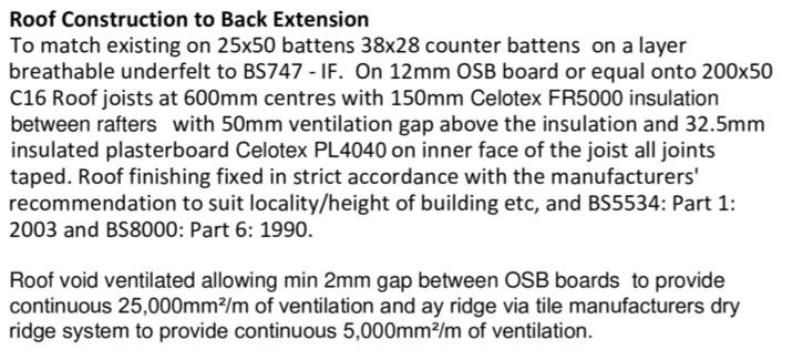
This is what by approved BC drawing says (it's a bad copy and paste by my original architect!) Issues with this are: 1.You cannot get FR5000 anymore or an equivalent; if the 3-4 places I have called today are correct and one girl in particular knew her onions so I don't disbelieve this. 2. PL4040 is 52.5mm as the 40 means it's 40mm PIR then a 12.5mm PB - so I could play this to my advantage and go with a PL4025 and still come out thicker than 32.5mm. (more on this later). So the first issue is that I cannot get the FR5000 so I need an alternative, now FR5000 had slightly better R value than a standard same thickness counterpart, so it may be that it was spec'ed not because of the fire rating but because it gave a better R value for a given thickness than a standard counterpart. So it was possible in my case to use 150mm to achieve what was needed and leave the 50mm ventilation void - had he spec'ed another product maybe it would have needed to have been 175mm for example. So my thinking is, I get some GA4000 or TP10 or something 150mm thick and put it in between the rafters, then I need a further 20mm of insulation to allow for the 32.5mm insulated plasterboard, so my thinking was a sheet of 25mm Quinn Therm on the underside of the rafters, tape it to act as my vapour barrier then use GTEC fireboard. However, as said above PL4040 is a 52.5mm product, I don't know if he meant PL4040 as in 52.5mm version or he meant 32.5mm and incorrectly spec'ed PL4040 as a product forgetting the second 40 = the thickness of the insulation on the PB. Because that drawing was approved I reckon I could make it fly if I used only 32.5mm and claim I thought PL4040 was just a product a bit like GA4000 is yet you can get it in 25, 50, 100mm etc. This would give me a ceiling construction with better fire properties, mitigates the fact I am not using FR5000 and takes care of the insulation thicknesses - as to the R values here well I am not sure, they may be slightly lower, but as no calc was done, just a written spec of the makeup I wonder if I can make that fly. I have also just discovered my BC officer has left so I need to work out who will look after my case. I am holding off contacting them until I have a new proposal. I have also submitted to Celotex the original spec and asked them to come up with a comparable one using standard products and taking care of the fire rating with fireboard. Just keen to hear what you guys have done on new builds and extensions, I guess as long as the new spec is better than the original BC cannot say anything, but I want to work out the best minimum spec first. I just want to take care here as insulation is an expensive business (single most expensive material in the whole build not including the kitchen!) and I don't want to spend money on materials I end up not being able to use or having to sister up with another product to get to where I need.
-
Sorry, I mis-read your post, I was sure you said 145mm and took it you were using 6*2's. Can you not beef these up a bit? 4x2's are only good for non-supporting stud walls and even at that they are a bit flimsy. With a proper makeup of flooring you are going to struggle to get a good solid tiled floor. What is the distance from your solum to your finished floor height? I think I would be adding some hardcore, sand blinding, DPC, concrete!
-
Stage 1 Is Very Nearly Complete :)
Carrerahill replied to Construction Channel's topic in General Self Build & DIY Discussion
Congratulations! It's going to be brilliant and don't listen to everyone who makes everything sound like it's all just difficult and near impossible - it really isn't - life will brilliant! -
Well indeed, we know now it is a retaining wall - Garden wall! Pfft!
-
OK - attempt No. 2! You will need at a minimum 140mm block with piers every 2-3m - so worst case 252 blocks for basic wall plus about another 120 block for 14 piers so £372 for block - £372 laid ton of sand and 10 cement £80-100. Found - digging this will be the biggest cost - £1000.00 - £200-500 for a concrete depending on hand mix or trucked in. I think 3K sounds fair actually. £1500 will be materials. 3-5 days work.
-
That ain't a garden wall! Back to the drawing board! Single skin 100mm block - no chance.
-
He said a garden wall. You said above ground so I assumed you had something. 28m of found for that size of wall - depends, excavator or hand dug - found may cost you £1000.00
-
25.2m^2. 252 x 100mm Blocks @ 85-90p = £226.80 (maybe £252 for 140's) £1 a block laid £252 Some brickies will want £2 a block (go jump) and some will take less - my brickie was £300 for 400 blocks laid absolutely perfectly! £478.80
-
Arrow HT50 Hammer Tacker. This is the only stapler I ever see the pro's with - and have one myself, far easier and better than the lever handle type designed for teachers to put paintings up in the classroom. https://www.orbitalfasteners.co.uk/en/products/arrow-ht50-hammer-tacker-arrht50p?utm_medium=google_shopping&utm_source=google&utm_campaign=google_shopping&gclid=Cj0KCQjwov3nBRDFARIsANgsdoFtxgl_pvZdPNQmb8U3M-Fh1d5TpZaSY6E7FQk6RB0YQ65gNBO7c9kaAsKQEALw_wcB
-
Wall plate would be the timber a wall is built upon, ledger board or runner board. From the structural engineer sitting opposite me: I would use M16 threaded, M12 is a bit small. C24 on that span is overkill and not worth it, C16 will be more than adequate. Bricks assuming not crumbling and poor will be of better quality than today's - they are also bigger so you can get a better depth. I would either sort the wall out so it can be done properly or remove some of it, level it, put in a wall plate and sit the joists over the wall. You may opt to put some forms in a pour a concrete pad along it to level it all - although 4 nails would probably hold it, it could fail under heavy load or a sudden impact etc. and it's not about situation now, it's about what happens in 10-20 years when something maybe gets damp or rots. Do this bit right. You are over thinking a 6m^2 domestic floor - the calcs seem off. A sleeper wall mid span for 2.1m is totally unnecessary. Can you post a sketch showing the section across the span - so it shows where the joists will sit - with some rough dim's on it.
-
Timesaver coupling - has anyone ever used one?
Carrerahill replied to Carrerahill's topic in General Plumbing
Yeah I did try to use them actually, but in the end I just built it to the BC approved spec: "47x195 C16 timber runner bolted to wall at 600mm centres with RAWL M16 R-KF2 stud fixings. Rafters fixed to runner with pair of Expament framing anchors with all holes nailed." I ended up using Simpson A35 framing anchors. The rafters are also skew nailed with 90mm SS nails top and sides. I was actually going to get hangers but none of the local merchants sold the sloped hanger that I would have needed and most of then had never heard of them, is this a regional thing? The roof is not actually finished as there is to be more framework to the underside and as part of it I am going to add some structure to support the rafters a little more. -
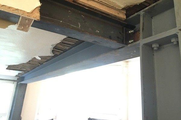
The lintel is not the issue, it is the bearing surface, you could use a solid piece of titanium but the fact is you are still trying to support a >1200mm span on a 100mm piece of the existing wall. Even with a concrete pad-stone it is not a large bearing surface. One option may be for you to move the whole opening left a bit and have a stub of wall (properly cut into the existing wall) built to give you the required bearing surface without needing to eat into the party wall, another option would be a vertical steel. Of course these two only work if there is a supporting wall lower down that you can build on. These are a bit excessive for your needs but give you an idea. If you take a hammer and hit the edge of concrete what happens? Move it in about 50mm and try again - same principle.
-
The engineering consultancy my wife works for is running and project managing an EU wide cladding test program - in fact, it is her project. Many testing companies are backing out and stating rather trivial details as the reason, it would appear that they are all aware that really any cladding made with anything other than a cementitious base or metal is going to fail. All these cladding products use plastic or cover plastic and I mean that in the widest sense, foams, plastics everything. Cladding for aesthetic reasons is going to be OK but if the purpose is energy conservation then really it is not a fire safe product. They are also looking at the environmental impact of the stuff and the CO2 and nasty chemicals involved may actually cause more environmental damage than burning a bit of extra gas or electricity to keep the building warm/cool especially as we enter a new era of clean power. I don't think we have used coal for over 3 weeks now. So do we stop filling our houses with horrible chemicals and plastics and just use a bit more energy and stick to good quality natural material based insulation?
-
Timesaver coupling - has anyone ever used one?
Carrerahill replied to Carrerahill's topic in General Plumbing
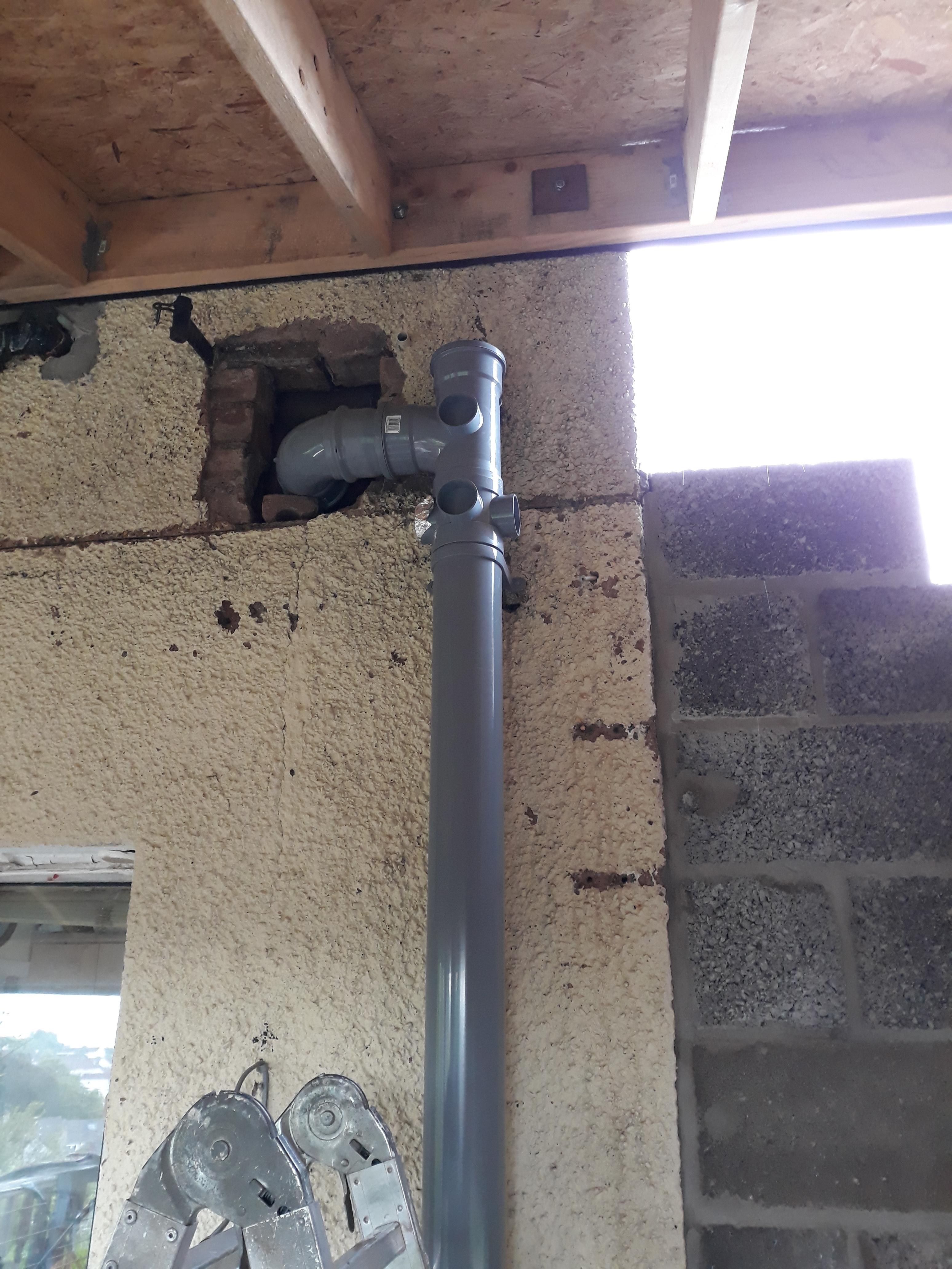
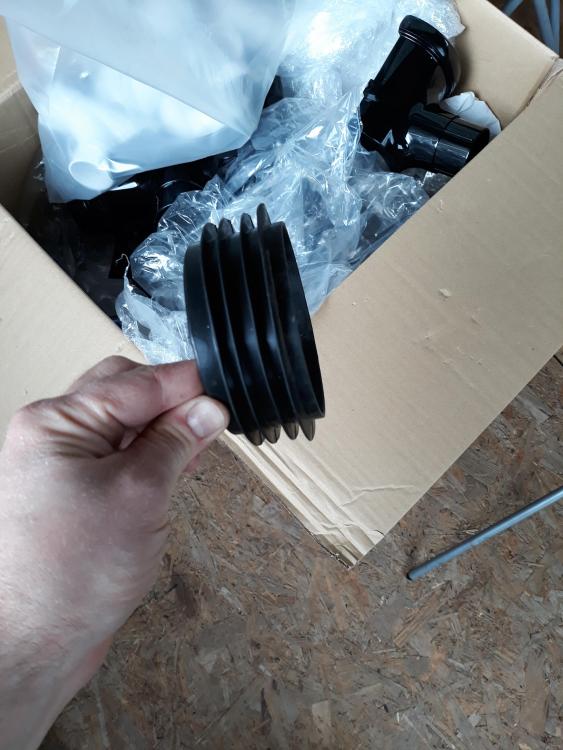
OK this is what I have done. You will recognise the connector from above links and images, mine is just modded a bit! So the spigot connector: Then removed seal from the spigot connector as this was NEVER in a million years going to fit: The finished product, I will leave it till tonight like this then make good the hole in the wall after I am happy it is leak free. The foil tape is where the 40mm waste will connect in in which will serve the bathrooms off to the left.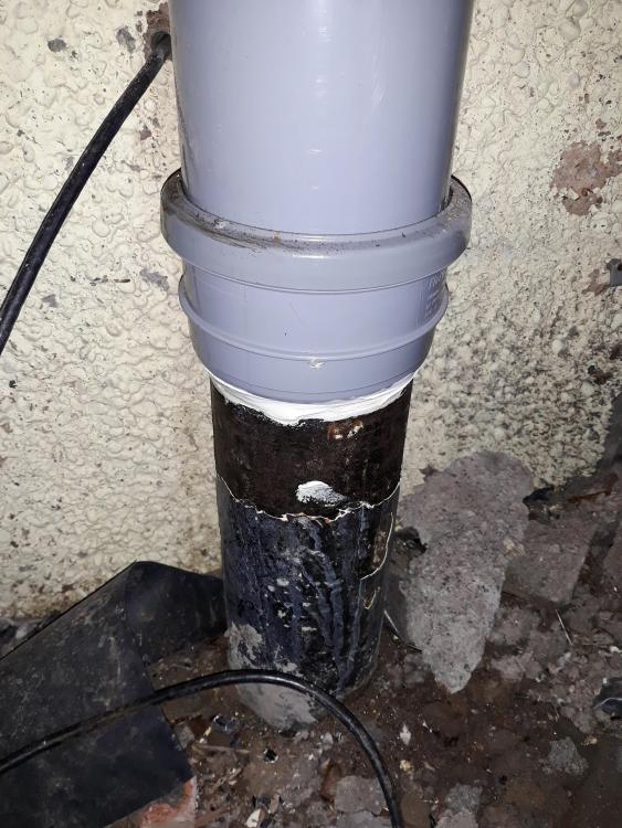

-
Timesaver coupling - has anyone ever used one?
Carrerahill replied to Carrerahill's topic in General Plumbing
Yes that is is the original cast pipe coming out the ground (now inside my house as it's in the extension). As for the Screwfix part you link to: Yes and no, see my original post I go through it all but the spigot with seal is too big on those, so as a component it is not the right one for the job. However, it all works now and that is what I used with the rubber seal removed so the plastic is just sleeved into the cast pipe with a big bead of quality sealant around the conical section which is now sitting on the cut face of the cast. I also smeared a little on the face of the spigot just too help gum it all up - in reality there should never be water trying to go up the joint, but if there was a blockage then it could be that this section ends up sitting full of water so I needed to know I had a good seal. All my 40mm stuff just arrived so I can now go and do the rest of the bathroom wastes. 2 mins and I will post an image.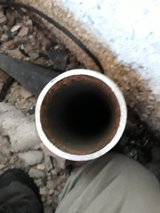
-
Timesaver coupling - has anyone ever used one?
Carrerahill replied to Carrerahill's topic in General Plumbing
Well in my case the cast is 101.6mm and the PVC is obviously 110mm. They didn't have anything (and they had tonnes) that would fit nicely around my cast pipe - but then again, I am led to believe it is an odd size... -
The existing lintel will not reduce the load on the new lintel it potentially will actually increase the load. The dead load and any imposed loads (if it supports any floor joists etc.) of the masonry above the existing lintel is being supported at two points in the existing wall this then creates a greater point load at the bearing surfaces, if you then transfer this down onto the new lintel you are actually going to create a higher point load right in the centre - weakest point - than if you just bricked up to the old lintel. What I would do is support the wall at about 3 points (depending on width of opening) 1 about 2 courses above the new lintel position and directly under the LHS of the old lintel, then another further left and above the proposed new lintel the third would be under the old lintel too just to take the weight of the wall above well. Then remove the wall to create your opening, and fit the new lintel, then build brick up under the old lintel well, with a good mortar bed pushed in hard so the old lintel effectively just becomes a long brick and is fully supported. The old lintels load becomes fully supported full length.
-
Hmmm, when do you need it, I should be up near Taynuilt in the next month...
-
Timesaver coupling - has anyone ever used one?
Carrerahill replied to Carrerahill's topic in General Plumbing
I tried those too - the one I tried was basically a parallel sided thing (that one is to go over the OD of clay which is much bigger than 4inch) it was a good fit on the 110mm PVC but had an even bigger gap around the cast - if the Timesaver was going to wrinkle up this boy was going to look like a bloomin' Accordion!