


Gus Potter
-
Posts
2342 -
Joined
-
Last visited
-
Days Won
29
Everything posted by Gus Potter
-
Good point ETC.. but those that do are few and far between.. and if they do they have often moved onto better things.
-
Hi Zoot. Seems like you are going great. Just had a look at the photo. Where are the drainage holes/ slots? ? Looks like you have a face drained window with no sub cill.. can you check, hopefully you are going to tell me I am blind or worse.
-
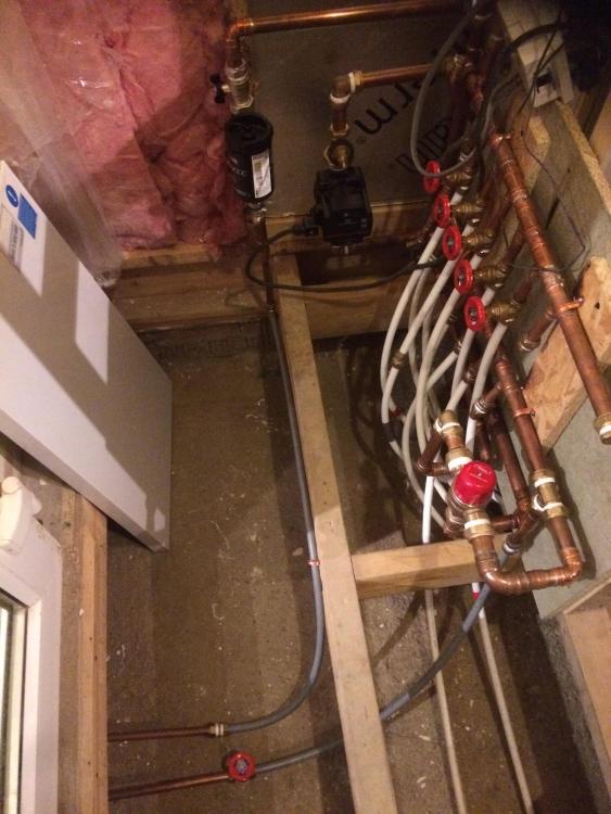
The close coupled tee is a good concept.. I experimented with this.. it worked for some of the time but not all the time. My rads have TRV's so things / flows were always changing.. or maybe I should stick to other stuff.. I probably know enough about plumbing to be dangerous! I made a home made manifold to test how I could couple an old council house up with a modern extension with UFH. It's working great so what luck! Photo uploaded
-
New build design & cost estimation opinions
Gus Potter replied to morgan_22's topic in Costing & Estimating
Well done to you both. The main thing it to also enjoy the journey! I wonder though about the layout of the kitchen living area and lobby. They say first impressions count. The first thing you'll see (and your guests coming for the great grub) when you come into the room from the lobby will be the kitchen and your cooking innovation / what you are up to. Also I think that they will see not least the narrowish space between the peninsula unit and the hob.. it could look like you are going into a small flat? You want the wow factor when you come in and that is the open living space and being able to see the fire place. Where you have the stair invites the eye..so take as much advantage of that as you can. I would look to create the impression of open space as soon as you come in the front door.. then tease with the staircase.. what else is up stairs??.. just how big is this place? Also remember that at say xmas the house could be full..where is the oven and where is door to open? Will an open oven door further restrict the kitchen activity space and pedestrain route to the ground floor wc ? Check the building regs for Kitchen activity spaces / accessibilty at this stage.. better to do this now. I can see you have got someway with the screen concept.. keep going. Have another go at the kitchen and living space. Things to think about are.. yes you don't want the front door open and a huge draft coming into the room.. but you can have walls that don't go all the way to the ceiling. This also lets you shine diffuse light over the top of them while still cutting out the big drafts. This can work both ways.. the living space could be dark with diffuse light coming over the top from the "lobby". It also means you can have kitchen units hidden behind. Walls can be solid but split with glass, again with careful choice you can invite the eye to appreciate the whole room as one space while still achieving the practical side of things. Don't get too hung up on the tree at the moment at that distance.. unless it was particularly large. Very roughly tree roots extend about the same distance as their height. Have a look on google earth and see how high it may have been. Much will also depend on your soil (not the stuff you grow potaoes in but the stuff under the top soil) type. You can do quite a lot on you own at the moment. trees put down deep roots (structural roots) locally so they don't blow down in the wind. They also send out other roots to gather nutriants and water. Dig a few holes in the garden just with a spade and look at the soil.. ask.. does it look like a good medium where roots will grow? Also look at the ground levels.. ask where would this tree have found water.. on my site or somewhere else. Trees are not "daft" the roots grow where water and nutients are easily avaliable.. this lets them save their energy for propagating. In terms of your structure. You have a good amount of solid walls so achieving overall structural stability looks reasonable doable cheeply. You'll probably need a transfer beam where the ground floor steps out it may just work as a beam alone as you have some return walls to stabalise the rear elevation. You have shown a ridge beam..good idea.. stick with this for now.. you may want to split it into three. If you do you'll need to take some point load down roughly where the hinges to the door to the master bedroom are. With a bit of finesse on regigging the lobby you could make this easy to do without resorting to unnecessary structural beams and complexity. Again the ridge beam concept lets you use say a simple cut timber roof, simple connections leaving plenty depth for cheep but effective insulation. -
Good news then on two counts. Getting approval and it looking more like a house than a garage! I love the different terminology as you move about the country. A really experienced Lanarkshire sparkie I used to work with vaguely pointed to a space in an attic conversion and said.. do you want the cable tray in the Camsile? Turned out it was the space behind the vertical soldiers (vertical struts also called the box member). Yes folk also use the term "cut roof" meaning the roof is cut from loose timbers.. a traditional roof Check this as it will depend on the the wind bracing you need, the loads and connections not just between the timber members but also between them and the rest of the structure. The prefabricated truss manufacturer's tends to stay away from this part of the design... the stability system and load transfer to the structure below. You may actually find your stick roof is the most cost effective option. Would be interested to see your plans also.
-
Wow.. these show a really fast results.. you are lucky.. but did you check if they are too fast? From memory there is an upper limit in the BRE design guide. Will stand corrected though.
-
Protection of ICF blocks in foundations
Gus Potter replied to Joey's topic in Insulated Concrete Formwork (ICF)
It's not easy! Starting at the end.. with the render.. you may want a bell cast bead at the base of the render. It needs a sound base. A big thing is for me is that it all looks great on a generic detail along wall detail but how do you detail the door thresholds? Can you later alter the building easily.. add an extension? Do you care? I don't think you need a water proof concrete, no basement and your internal floor slab is isolated with DPC / DPM. If you are really wanting to go ICF then consider an engineering brick course say up the outside, it you want a clean detail at basecourse level.. they do look smart in the right place. Stop the slab short and take extra insulation down on the inside. I know you are seeking the perfect solution but always ask.. at what cost and how durable will it be. Once you get a handle on this do you do a trade off.. I would look at putting more easily installed thicker insulation elsewhere and accept I may fall a bit short in other places. Remember you could have the perfect insulation design, avoid cold bridging.. but if your trades persons can't make a good job of it then it is not just false economy for you but also bad for the environment. Lastly ICF.. there is a time and a place for this.. I support the concept and understand how you reinforce the concrete, detail the corners rebar wise say / openings and design a raft found if need be and so on.. frankly folks this ICF stuff is nothing that new, it boils down to the fact that we are using insulation as shuttering (yes we have some cute wall tiea) and using insulated raft technology that has been proven for the last 50 years.. For insulated rafts the calculations are a bit longer.. it is about two lines of sums and one short written paragraph of explanation of how you have derived the values. You compare the different elasticity of the EPS insulation at a certain compression (usually 10% and convert that down to say 1 -2% and derive a bearing capacity from that) cf say clay or sand soil.. I am not kidding you! And folk think this is magic.. it's not.. it's basic first principles. An experienced Contractor say @saveasteadingthat has done tens of thousand of square metres of insulated floors will tell you what works and what does not.. we can use these same principles for our houses and that will drive the cost down.. we just need to convince say the NHBC and BC that it does work. The theory is internationally well understood. The problem is getting it to the mass market in the UK and knowing when it is the right solution for the self build market at this point in time. And that is the current issue.. unless you are building a very big house not in Scotland or Wales then the economics don't stack up? And after that rant @Joey is ICF your thing? Gus -
Spot on.. Yes it is an inner city garden but there is often no need for panic. If neighbours get together and are of like mind then you can do a lot and not trash your founds or patio. My neighbour over the road has just astroturfed their back garden.. and the number of jobs I'm starting to see where they have done this.. is not good when you take in aggregate.
-
Have a look at the design. It may be that althought the wall is not carrying vertical load it is carrying horizontal load from say the wind blowing on the outside walls? Best thing you can do is to provide more info to get a more defined answer.
-
These are some really good questions. Yes you'll read a lot about trees, their roots and also some horror stories. In some ways.. I think that there may be two issues here. One is that your neighbour has planted a tree that could overshaddow say your garden when it grows without thinking of the consequences. Folk do this.. they like a kind of tree and don't realise how it can impact on their neighbours. Also the hedge.. For you, your first step maybe is to maybe think about how simplistically trees grow, large shrubs are different a bit . Trees that grow big (tall) need some deep roots, they stop them blowing over in the wind. They have other roots that gather nutrients and water and these are close to the surface and spread a long way. They follow the path where they can expand and are close to the surface.. hence why you see these roots under your slabs.. you may have a nice bit of sand bed that encourages the roots to spread, there will also be some very fine roots. The funny thing is that as you have slabs the roots have no competition from weeds and other plants.. you can't blame the tree for taking advantage of this. These secondary and tertiary roots seek out nutriants. To get a handle on this identify the type of tree. Decide if you like it, could be a say a cherry / hornbeam that flowers and looks great / stunning! Could add to you enjoyment of your garden even if not in your ground. If you try and understand how the tree grows, the kind of soil you have and where you live ( Kent or Shetland diiferent rainfall) then you may be in a much better place to manage not just the tree but your neighbours! Now the laurels are a bit different! They are not that fast gowing but they are sturdy! I think. Again though your best approach is to start with understanding the ground and one tree. Engage with your neighbours. You could say.. what do we need these trees for. Do you want privacy? But I too want privacy.. but don't want my house damaged! I may come over as a bit soft here but what you are doing is to establish the facts and groundwork should this escalate into a dispute that you need to involve say an SE. It could be a case of stick and carrot here. The best way is to use persuasion. if that does not work then further persuasion with a hint that you may hold a big stick!
-
Hi Barry. Attached is bit of one of my right in the background working spread sheets that I use from time to time to get a handle on how this works. It does not come out that well, some of parts of the graphs are on different pages and so on and also I don't want to give away too much of my IP. Tommy is the guy who dug the test holes. You'll probably clock that there is a bit work that that goes on behind the scenes and that is why I attach. They won't suit your site but I adapt my calcs and design philosophy on a site to site basis.. and tweak the spread sheets.. yes you can get software to do this but I like from time to time to use firstish principles and adapt to the geology of the site rather than just saying.. the computer says no. Yes you are right.. partly. Yes give this a go, nothing to lose. For folk to help on BH we need to know a lot more about the profile of your site, where you are.. assume you are in Scotland (use of burn rather than stream) then give us some local clues! I would say to you.. don't focus on the calcs at this stage.. look at your ground, the topography, get a feel for it and rely on your common sense.. will serve you well. Clay soils do not drain well generally.. but there are ways around this if you have a bit of room to play with. Check this first.. has he worked a flanker or is this ok? Tell us what you know of the burn.. what do know about it? does it run almost dry in summer? here we want to know dry weather flow as does SEPA. Also if you are say located near some parts of the central belt / Perth catchment area for example they have a big problem with flooding as they have build schemes of houses in "flood planes" .. we need to know about this. Once you get your head around this often a good solution jumps out. But you'll need to do the work first. Then you do the calcs to prove to BC etc you were right all along.. oh the satisfaction! Hope this helps. Rain water calcs prelim.pdf
-
It is indeed. @pocster.. thanks for the response.. it took me a bit of time to write that while trying not to sound too much like an.. @pocstercan fill in the expletives.. I maybe failed as concrete lintels are not that sexy.. The thing I like is that there are folk here on BH that have forgotten more than I know an don't mind sharing their knowledge and experience.
-
Hi pocster. That looks like a typical lintel that may be produced by say Robslee, they call it a type A lintel which is what we call a composite lintel. It has the rod in the middle. For all they are two types of generic lintels, one is called a composite lintel, the other a non composite lintel. They are two different animals. The composite lintels tend to have the rod in the middle and a bit of prestress in the rod to keep the concrete in compression, also helps it not to fall apart while you are laying the bricks above. Long composite lintels need to be propped until the brickwork cures so read the manufacturer's instructions. If you have a good height of brickwork above they can span quite a long way if you are careful. If you think about a reinforced concrete beam. It has steel in the bottom with a bit of cover to the steel to prevent corrosion (plus often fire protection) and provide bond between the concrete and the steel rod / wire. Concrete is good in compression, steel good in tension so when you load up the beam from the top the bottom goes into tension (resisted by the steel) and the top into compression (resisted by the concrete). Now for a composite lintel you can mix up materials. You can have a rod encased in a bit of concrete, like your's pocster. If you make sure the top of the lintel is clean and put say 5 -7 plus courses of brick (see manufacture's spec) on top then you now have a deep beam.. (the top 80 odd % is of brick if you have 5 courses or more of brick) .. the depth of the lintel plus the brickwork above and that works quite well in places. In fact surprising well.. What happens here is the courses of brick above acts in compression and the rod in the lintel is in tension. The concrete in the lintel is not doing that much. In other words the brickwork acts compositly with the steel rod / wire in the lintel.. like say a SIPS panel where the sheeting and internal timbers act together and to make this work the sheeting has to be well fixed to the internal timbers.. thus the brick work has to be well bonded to the top of the lintel and the perpendicular ends of the bricks fully filled with mortar. In summary the lintel per say does not act to resist the majority of the bending effects.. the concrete around the rod / wire just acts arguably as a medium to transfer the horizontal shear forces (tension) in the bottom side of the brick to the rod in the lintel, which happens to be encased in concrete. A big mistake folk make is to put a DPC (cavity tray) between the top of a composite lintel and the brickwork above. Here you create a slip plane and the whole system stops working.. please don't do this. Now a non composite lintel acts much more like a reinforced concrete beam. The major difference is that it does not rely on having masonry above. This lets you introduce say cavity trays and put floor joists on it for example... maybe a bit of point load. The rods are more heavily prestressed and are in the bottom. They are marked top. If you can't see the mark, (sometimes the lintel may have been cut down) then look for the rods and put them at the bottom.. unless your SE tells you otherwise. Sometimes you can use a lintel upside down to create a cantilever / corbel but this is not that common. Prestressing? An ordinary precast reinforced concrete beam has say steel in the bottom, a rebar cage is made and the concrete poured round about it. It all cures and you load it up. Now steel is quite a stretchy material so when you load up the beam it drops (deflects) a bit before the steel really starts to work. The concrete is also a bit elastic so it has to "shorten" on the top of the beam and this gives rise to more deflection. Also concrete shrinks so that relaxation has to be taken up and that can manifest as more deflection. When they make lintels they don't make them one at a time. Commonly they have a very long mould and run a long wire near the bottom. The wire is put under tension and the concrete poured and cured. Then they release the tension blocks at each end of the wire and saw up the long prestressed beam into common lintel sizes. Once they release the tension blocks the wire in each section of lintel it wants to shrink, but it can't as it's bonded to the concrete in the bottom of the lintel. What happens here is that the wire compresses the concrete in the bottom of the lintel and this makes it bow up a bit.. which is good as when you build it into your house it bows back down. the idea is that the bottom of the lintel ends up about flat... in an ideal world.. just like us on BH! If you are curious if you take a longish non composite lintel.. say a 145 high x 100mm wide (type C that look like a concrete beam higher than it is wider) and lay it flat with the rods near the bottom you should see a bit of a bow upwards. But @nod some non composite lintels do have the rod in the middle!! and !!! The explanation for this is very lengthy but so have left it out. These tend to be wider and flatter. There you go.. hope this helps to give you a flavour of how the different type of lintels work and hopefully this will help you select the right lintel and use them in the right way. For me I tend to stay away from composite lintels on longer spans even if I have a good few courses of brick above as the workmanship / site supervision is often so poor these days. Yes I know the heavier non composite lintels cost a bit more but they are more "idiot proof" to some extent. Also, on self builds we often make late changes so non composite lintels give you a bit more flexibility here.
-
Maybe aye, maybe naw! @James traversIt would be help to know what the inside looks like. Can you see any cracking from the inside? To be able diagnose something like this you need to gather a lot of info. If I was doing this I would start by looking at the whole house and the houses round about (if you do have close neighbours) to see if the main house and the other houses are showing signs of movement. Also, I would look at the terrain, generic type of ground and so on and anything else I can see or suspect.. its a long list! Often what you do here is to get a feel for the place and try and work out what it can't be. Then work out what it could be and start to focus in more detail on that. It all sounds awfully complex but you want to make sure you have checked and ruled out say mining or a bit of weak ground strata that if you miss it will be a major clanger. Once you know you have ruled out certain things you can then say.. yes this is a localised problem and ask.. what could it be? That is a good place to start and can reveal more about what kind of movement is taking place. It's a fascinating thing to deal with.. unless it is your own house! The main thing is not to panic, once you understand what is causing the cracking you can then decide.. do we just leave it to settle down / monitor and repair the crack after a year or so.. or will it get worse, if so what can we do to mitigate this.
-
Often you see this type of cracking. The cracks down the wall seem to be of uniform width.. suggests at the outset shrinkage say of concrete blocks / render rather than settlement. If it was settlement then often the crack wiil be of a different width top to botom, not always, but that is a common feature. But .. where the roof meets the existing wall the crack seems to continue in the existing elevation? That raises a few questions as you would not expect to see this. @James traversPost more photos if you wish of what you have round about and if you have been slapping out walls... doing the open plan thing.. I wonder.. if you have an old house and slapped though to make the opening to an extension with good solid founds ..have the existing walls settled as you have added load locally to the old bits of wall either side of the slapping when you put say a beam in.. Look really closely at the crack and try and figure out what has moved down or up relative to the other interface. Look at the rest of the house wall and put your "Columbo" hat on. Have you had a really dry spell and the old building has dropped a bit more than the new extension? Don't always assume that the new extension is moving.. a good extension with "well" designed found tends not to.. but add load to an old found and the existing wall locally loaded for example by a beam over a slapping could well move a lot more than you think.. start at 15- 25mm for a shallow footed old building found in certain types of ground (clay) a bit less on sand / negligble on rock ! Help ma boab you may ask 15 -25mm .. but old buildings move a lot! That kind of movement is well outside say NHBC / BC tolerances but old houses are a living thing. If you build a modern extension with stiff founds that stays still these kind of cracks occur as the old building is moving about relative to your solid extension. Don't always assume that your new extension is the problem. It can be that it (extension) stays still and it's the house that moves up and down. And there is the rub.. BC want an extension built to be bomb proof with no account as to how you marry this into an old structure that moves up and down with the weather as it further ages.
-
You have a bit of thinking to do here. Don't go sticking a trench under where you may want to put a future driveway, you'll get caught out when they ask how you are going to deal with the run off from the hard area of the drive. You may say.. permeable monoblock or say open textured asphalt, BC will say.. but there is a drain already using the infiltration capacity of the soil under... please provide calculations. Also these things are supposed to be maintainable.. under a driveway with associated soil compaction.. thus reduced infiltration rates and so on..? Have a word with your designer about your future plans, maybe a swale with some storage capacity either side of the future drive, could even try a simple orifice plate with filter at the ends to say reduce outflow to 5 or 2 litres per second into the water course. BC etc may accept this as it is a very small scheme? If you only are predicting 2.2 cube of water then this will equate to small draft of water in a shallow swale of a reasoable length. Let us know how you get on with your SE.
-
Rather than a surveyor get a hold of a good roofer and pay them a couple of hundered quid to come with you. If those are the original tiles and you are doing this as a long term investment then expect to re tile and batten + membrane, you'll probably have plans for the attic anyway to try and make more space?. The nails on the tile battens will be a bit sick in places. The flashing, verges, fascia boards and chimney flashing are probaly past their best anyway. What you need to also check is the roof timbers for rot and wood worm. You need to go and see it and get into the attic with a good light. Lastly check how many habitable bedrooms there are upstairs, the width of any existing staircase and the building regs on stair case requirements for the number of habitable rooms in the attic. That may have an impact on how you develop the attic (if that is what your are thinking) and what you may need to reconfigure on the ground floor to make a stair compliant.
-
Barry.. unfortunately not. If you want to learn a bit more about it then get yourself a copy of BRE digest 365 link below. Will cost you £28.00 but it will give you a grounding on this. I would give you my copy but will get hammered on copywrite if I post it. https://www.brebookshop.com/details.jsp?id=327631 It takes a lot of stone to fill a trench like this, also you have to do something with the muck away, geotech membrane on top. A few rough points. The trench will probably serve to act as a partial soakaway.. good in the summer when you have low rainfall but in concentrated bursts, more pollutants on the roof from birds and just general airborn pollutants. This is when you really damage the habitat. River / burn / stream flows are low so a small bit of highly polluted water off your roof during the start of rainfall can do a lot of damage to the ecology. In the winter flow rates in the water course are generally higher so more dilution, more regular rain washing the pollution off the roof in smaller concentration. In the summer you can get really high rainfall in short spells, more so in England . The idea is that the first bit of water that comes off your roof gets stored in the trench, then as it fills it gets diluted before fully filling and entering into what you hope is a river / burn with an increased flow. The trench is filled with stone with gaps. The gaps (voids) form the storage volume.. hence the apparently large trench. Can you do a pond / retention basin / swale with storage. If you have a bit of space this could be a great addition to the garden with a bit of clever planting? Ponds don't need to be round and you can select plants that do well in both dry and filled pond conditions. Once you get your head around the theory you can use your imagination. If you have a sloping site you can create bunds to a certain extent so a " pond" can be above the original ground level once you have regraded. Clay soil is your friend here. In the round have a look at what you have got and what you could do. You may save a bit, even if you need to pay your SE for another design. Then if you can go the pond way or say a swale you'll get your money back out of the enjoyment of the garden? I hope you are not intending to put your driveway say over the trench?
-
Yes you could transform that. I would be minded to remove the low walling to the right. Check the split block / decorative stone is sound then bond it all out in undercoat plaster with some corner beads, plaster skim coat and square it all up apart from the inset bit around the opening. Then stand back and have a look. Think, how would it look if we continued the cornice round. Next check the flue. That looks like a relatively new house so you may have chimney with proprietory flue blocks, already fully lined. After that you can decide on whether you want to have an open fire or a stove and what inset.. could be tiles and what mantle piece you prefer if any. Lastly there is an old rule of thumb to get your open fire to draw. For single storey you take the opening area of the fire place opening and divide by 8. This gives you the cross sectional area of the flue. For two storey you divide by 9. That is all provided the chimney extends sufficiently above the roof and that you have no large trees nearby or large buildings. If so you need to check chimney height outside and select the right cowl. Hope this helps give you some pointers.
-
For all. We have a new bit of dual carriageway nearing completion in EK. One of the roundabouts has astro turf in the middle and nearby a big SUDS pond, probably designed by some that have not thought it through. What message does that send to the kids who go by it every day on their way to school? I wonder if when they designed the SUDS pond and the organisms you need to promote for them to work properly they thought about the micro plastics and initial filtration / first steps in the treatment train? Although of SE bent the number of sites I visit where folk are astro turfing thier gardens is noticable. That said some boy racer has already churned a bit of it up. Well done son! Will take photo and post next time I pass.
-
Moved to EK about ten years ago as wife's family live here. One day I left the house I had bought and got lost in EK (called the roundabout city..) and it took me about two hours to find my way back.
-
Simon.. yes that is the joy of Scotland.. you get four seasons in one day.. the sheep are white.. lovely to look at as they get washed nearly every day.. our central heating kicked in this morning in part of the house.. summer in East Kilbride.
-
Go for the simple stupid. Classic warm roof, the furring pieces are the least of your worries. Before you get too technical try and work out how you will detail the interfaces ( you need to keep the SE happy) and if you can find someone (builder) who will be able to follow the drawings and build it at reasonable cost. Also, you'll need good drawings unless you want to be on site every day. Get a feel for these costs and then look at what it will cost you to make the insulation thicker with a simple design. Your first challenge is going to be to find a builder who will take this on. Next you'll have more labour cost, a detailing cost and site supervision plus a few other things to think about, all on top of all the other day to day stuff. You mentioned C24 timber. What centres are your joists? If 400 centres have you priced / asked your SE if 225 x 75 C16 at 600 ctrs will work, maybe 200 x 75 C16. Often we look at tables, assume a certain joist size at a certain spacing.. partly because we also need to look at repeating bridges for the insulation. With a true warm roof you have much more scope to play with the joist depth width and spacing and see what is going cheep at the time.. who said it was easy!
-
Like your train of thought @JohnBishop On the face of it you can use vermiculite for plant pots, good for retaining water apparently. I'll defer to others on BH but I don't think it is hydroscopic.. has been use a lot in the past for house insulation. So yes it will hold water if it gets in. I suppose you need to make sure your chimney is in good order, capping, flashings, pointing render and so on. In some ways it may be good that it can hold the water, if not.. it's going to run out the bottom and onto the top of your stove or appear somewhere in the chimney breast above the stove as a big damp patch. If you have your stove on regularly it should drive off any moisture, even if just on a slow burn. The question is what else can you use to insulate a single skin liner that will get round all the contortions in a flue also given that a single skin liner when installed does not centre it's self in the flue. Folk these days want to have a stove that will just tick over but still draw.. thus you need to keep the flue pipe warm.
-
That's interesting. Did they explain why it leads "flue rot" and who does not recommend it? Is it because often the flues are in bad condition and they end up getting the blame or is there a fundamental reason not to insulate using vermiculite? After all it is common to line a flue if it is a bit "leaky".. in less than perfect condition. If you can find out as would like to know, Ta.


