PeterW
-
Posts
18480 -
Joined
-
Days Won
207
Everything posted by PeterW
-
We cut ends of rolls of vapour membrane into strips about 50mm wide on the chop saw and then use it stapled to the rafters. Seems to stay put.
-
What is the outer treatment of the beams ..? Are you using render board or are you hoping to brick the outer beam in ..? You can sandwich EPS between them but usually it is just hollow and you insulate the inside of the flange.
-

Where to put the electricity meter
PeterW replied to MortarThePoint's topic in Consumer Units, RCDs, MCBOs
Build a kiosk 3m from the pole, get the meter terminated there and then run your own 25mm armoured as you’re not limited to 43m. -
Buying a 'traditional' new build! (Persimmon?)
PeterW replied to Andeh's topic in General Self Build & DIY Discussion
@Andehh I can give you the full persimmon experience … I’ll promise you the earth, charge you a fortune, make you wait 6 months longer than I said to start with and then when I hand over the draughty shed you thought was an executive residence you’ll feel the way a lot of people feel when they do what you’re thinking …. Don’t do it !! -
Requirements for Heading to Committee
PeterW replied to BristolBuild2020's topic in Planning Permission
So you’ve got outline, submit and see what happens but if they write and ask for an extension just politely decline … -
Requirements for Heading to Committee
PeterW replied to BristolBuild2020's topic in Planning Permission
Have they written to you asking for an extension or is this anecdotal ..? A single councillor cannot get everything called in, and if they did then you would go to the LA Ombudsman first for abuse of power. Don’t forget, you’ve not lost yet so you can’t appeal a decision until you have one ! -
To echo what @Iceverge says… you need to look quickly at that design as it is barely building regs for insulation ..! What is the purpose of this 140mm block with another skin for the render ..? The mix of TF and blockwork doesn’t make sense, and the blockwork insulation is definitely not enough. Airtightness in this will be a real challenge and there are gaps in the VCL (vapour control layer) that are visible in the plans above. Roof design makes no sense either - they have specced Kingspan NilVent (clue in the name here ….. ) which is a breather membrane requiring no air space below, and then spec a minimum 50mm air gap. I would hazard a guess that they also had lunch with the Kingspan rep last week as I’ve never seen it specced so much on a set of plans ….
-
3600 bricks is 9 packs - that is a lot to handball and also not damage the bricks as you do it ! Have they not got a vehicle with a moffat on it so they can take them on to site for you ..?
-
Pretty much yes - get an element that is at least 50% of the height of the rail though as they don’t heat well unless there is a decent length of element in the side rail. No real need to use inhibitor - get some cheap antifreeze from the motor factors and water that down.
-
White tee - do not turn the bolt that is the plug for the meter !!
-
What is its total power draw ..?? And .. why..???
-
This seems a very expensive “just in case” option for something that very rarely happens. If you’re trying to protect sensitive kit such as CCTV or that sort of thing then use an off the shelf UPS..! Most modern fridge freezers will stay cold for 10-12 hours minimum and it’s not like you can run your ASHP so why not fit a wood stove too as heating backup ..??
-
Maximum demand greater than 100amp single phase ukpn
PeterW replied to Newbuildnewbie's topic in Electrics - Other
But you would have to be charging your car on a very cold day with the heat output set to 50°C whilst batch cooking a lot of boiling soup …. Diversity is there for a reason and this is also why Western Power are pushing 3Ph heads into new builds so you can put your car on one, ASHP on another and then leave the house on its own phase. -
Lift it and put a few cuts in the back of it and squirt a bit of foam into each cut then re-lay it with a couple of blocks on top to hold it down if you really want it flat but your screed will push it down tbh with the weight of that. Don’t forget the slip membrane under the egg crates.
-
Thanks - I would start by emailing the SEng the photos you’ve got and ask their advice as an initial step as they may make suggestions without coming to site. But they should be the first port of call.
-
How far up does the pebble dash go and is there a lead flashing up that wall..?
-
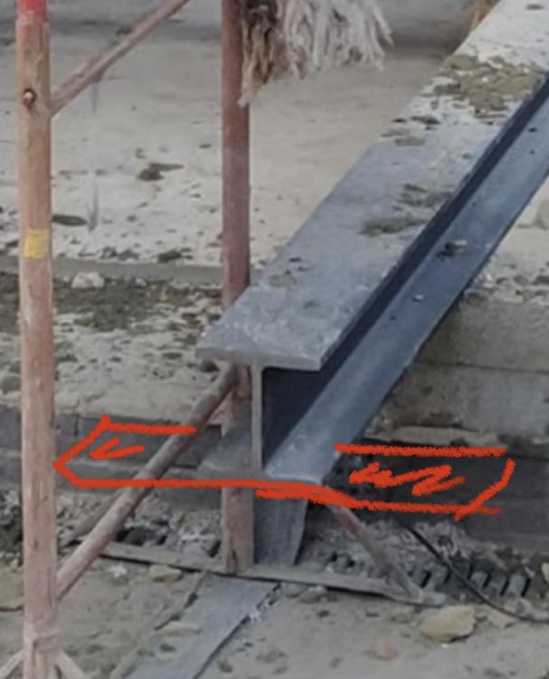
So the crap notch beam has a 12mm plate on the top of it to hold the two skins of wall that are above. Basically this is to be able to use a narrower (cheaper) structurally strong beam with a thinner profile and then add some more width to the top to take the thicker wall. Likewise, when you want to spread load you add plates that go perpendicular which stop what is called point loading on the brickwork which could crush it, especially if it’s not engineering bricks or padstones. Where in the UK are you out of interest ..?
-
very non standard ..!!! Talk to your BCO about what they want, you need to use the blocks to keep level and also remember that a cast floor isn’t structural unless it’s been designed that way so building your entire internal load bearing structure off it is a bad idea !!
-
on the end / under the end should be a plate like this - forgive the crap drawing as I’m on the phone..!! It is designed to spread the load of that beam along the brickwork
-
Yes it’s unsafe. You don’t take half a supporting structure down then go home for tea as it’s late. Each pin (or needle depending on where you’re from) should be left in place until the mortar has gone off on any brickwork which is usually 72 hours then they are removed. That means you take the lot out, one at a time and it should be done safely. Not entirely convinced however I would be removing anything until that joint is corrected on the steels tbh as there is a lot of load on the 4 bolts which look the wrong size too.
-
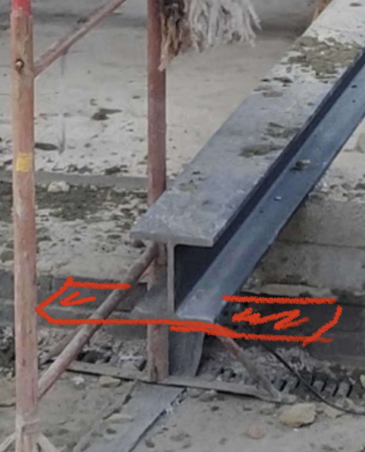
Ok so that was a single beam ! That is seriously heavy to move but they have done it. The end of the beam you have taken a photo of is wrong though and needs correcting. The engineer needs to see that too. Also, the beam inside that crosses over the room (Beam A on your plan) doesn’t appear to have the plate on the end as described - there should be a 600mm long steel plate to form a “T” at each end but I can’t see it on the photos, just a concrete block. That will create a point load on the steel and on the masonry.
-
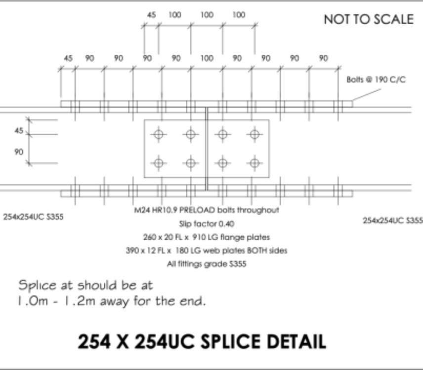
Somewhere in the large front beam there should be a join (unless they have used one very heavy single beam) and it should have a join in it that has a number of bolts in it like in this picture. The top and bottom flat sections should have 20mm thick by 900mm long with 20 Bolts in each plate. Either side of the flange (the upright of the beam) should be a plate with 8 bolts through it. The splice also should be no nearer than 1m to a wall.
-
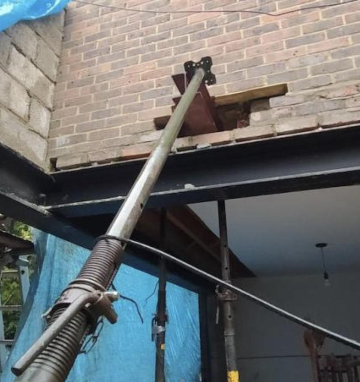
it is holding up the end of a steel pin (the bit through the wall) that weighs probably 90-100kg. If it slips, it will fall and kill or seriously injure the person it hits. It’s dangerous - to the point I wouldn’t go on site if they were left like that even wearing a hard hat !
-
That is not to spec so the joint is not correct and not structurally sound. It means there is excessive stress in the joint and it could catastrophically fail without warning. The notching could have created a stress point in the steel that will also weaken it. That could be repaired on site with a pair of angle brackets either side but would need the engineer to sign off on it and provide new calculations. The current install also puts load on the bottom flange of the larger beam which is not as designed so this needs recalculating. @Gus Potter anything to add..? Where are the splice joints too as I can’t see them in the photos .??
-
Oh and this is about as dangerous as it gets … That is the worst way to load an acro prop, and it could have brought the side of your house down ..!! If HSE saw that they would come down on him like a proverbial ton of bricks ..!