andyscotland
-
Posts
638 -
Joined
-
Last visited
-
Days Won
1
Everything posted by andyscotland
-
A lot of sparks would frown at it but AFAIK there's nothing specific in 7671 to stop you. The round pin lighting sockets were really more to avoid a nasty surprise when you plugged the iron in and plunged the room into darkness. A socket on a lighting circuit might also have thrown up issues like RCD protection under previous regs, less of a problem now RCDs are more widespread. Off the top of my head there's various general regs that would apply - safety on power failure (the iron example), nuisance tripping, clarity of what circuit actually supplies the socket (to allow for maintenance isolation) etc. Most of those can be dealt with one way or another. But in general so long as any cable is appropriately protected upstream for its current carrying capacity I don't think there's an insurmountable issue. It's ultimately not that different to populating a consumer unit with 200A worth of MCBS on a 60A incomer.
-
@Carrerahill All fair points and I wasn't aware of the MIET report. Nonetheless, I'm still not a fan of the failure modes for ring circuits especially for DIY design & install. For benefit of others (this won't be new to you) the cable protection depends on a reasonable division of current between the two halves of the ring. If the ring is broken, or has local areas of higher resistance due to damaged conductors, it can appear to function but be dangerously overloading one leg. This can continue for long periods without detection causing insulation breakdown (or more rapid overheating). With a radial a loose connection can still cause local arcing, which can often be smelt, but a damaged or disconnected conductor will usually cause the circuit to fail and/or trip. Granted, my background is in theatre/event/industrial where almost everything was radial so I probably have an innate dislike of ring. To be honest in the modern world I don't think a 20A radial to a few 13A sockets is all that limiting (outside perhaps a kitchen or workshop or other special locations). There are very few high-current devices these days. But even if it had to be on 4mm then personally speaking that's probably the way I'd go.
-
Personally, I would use a radial for the sockets too. With a ring there are a lot more ways in which poor design or a loose / overtight connection, damage to a cable etc can leave it in a state where it's working but dangerous (fire risk, primarily). The testing is also more complex. Depending on load, a radial may require slightly thicker cable (but half as much of it), but is a lot more bulletproof.
-
Solar VAT
andyscotland replied to eandg's topic in Self Build VAT, Community Infrastructure Levy (CIL), S106 & Tax
Quite. Of course, they don't and almost certainly won't. I suspect the government's argument would be that the panels are equipment and so standard rated the same as e.g. your consumer unit or any other fixed components of your domestic electrical installation. But of course buying solar panels you're effectively pre-paying for the electricity they generate so it does seem reasonable they should be taxed the same as other forms of energy. -
Solar VAT
andyscotland replied to eandg's topic in Self Build VAT, Community Infrastructure Levy (CIL), S106 & Tax
Seems about as short sighted as usual. Could be justifiable on a new build as part of the trade-offs in SAP, so really doesn't need to be zero-rated there but will be by default. While for retrofit, which is where the bigger carbon saving potential lies, as you say with no FIT and full VAT it's a much trickier sell... -
That's what I hoped you'd say, hate those wee moments of self-build-self-doubt! Onwards!
-
Lord no, that would be insane! Would be sure to miss some again putting it back on so it'd be a never-ending job ? I took out the screws that missed as they went in and replaced a centimetre or so away. So the holes they left are empty. Almost all of the holes that missed still scraped the joist so would probably be tricky to tape reliably from below, as they're right in the corner of joist/OSB. But as I have another VCL going on the bottom of the joists/above the ceiling I'm not overly worried. At least I think I'm not. ? I could try and squirt a bit of expanding foam in to close the hole in the insulation layer, but I think that'd be pretty messy given they're such narrow holes.
-
Any thoughts, anyone? I'm thinking leave them but wouldn't mind a sanity check!
-
@Simplysimon @Mr Punter the wafer head screws have worked a treat, very firm grip on the boards and really clamping it all together. Got most of them into the joists ok first time but a few missed (I could actually tell just from the difference in torque at the end). So I now have some 6mm holes through the construction. Not sure how worried I should be about this? Can't see they'll make much odds to the insulation performance. They have punctured the VCL between bottom deck and insulation. But that is belt-and-braces to follow the GRP manufacturer instructions. There's another vcl still to fit on the bottom of the joists, sealed to the walls, which will be intact. Should I do something about them, or leave them?
-
I actually think the crucial sentence in that PDF is on the next page : "I presently know of no reason why electrical wiring installed in accordance with the Electrical Safety Code will not operate safely in buildings where the thermal insulation is of the Icynene type". I found a copy of the 2012 edition of the Canadian Electrical Safety Code online and from a cursory search it says: I haven't done a detailed look at their cable tables etc so I don't know if they specify in the same detail as BS7671, or if they leave it to the installer, but it's fairly clear they require precautions against overheating. And they probably did back in 1987 when that letter was written. Therefore I read the electrical inspector's letter as meaning "there's no reason why Icynene poses any specific issue beyond what you'd have to consider with any sort of thermal insulation". Not "Icynene magically absorbs and disperses heat from the cable even though its entire function is to do the opposite of that with all other heat sources". Somewhere along the way someone has misunderstood, or misrepresented the advice. Possibly if their recommended detail is that cables go in at first fix then you could (in some constructions) treat the cable as adjacent to a conductive surface at outside air temperature, rather than as being enclosed in insulation. I actually think that's marginal given the spray foam is likely to get most of the way round the cable, unless you had it in square ducting or whatever. But either way you'd definitely have to make some allowance to derate the cable from its free-air value. I think that's quite a charitable view. I'd be very surprised if many developed countries don't have similar regulations, albeit varyingly proscriptive/detailed. It's basic electrical science that one of the key factors in choosing a cable size is the heating effect of the current passing through and the effect of the resultant temperature on the adjacent building materials and the conductor/sheathing/electrical insulation of the cable itself. It's also basic physics that wrapping it in insulation vs hanging it in the open air will have different effects on that. In the nitty gritty of 7671 you're even supposed to allow for things like solar gain on cables if applicable. Hence, of course, why the regs here haven't changed significantly for a long time - the science of electrical heating is fairly well understood so there's not likely to be much need for change. Very good question. As far as I can see "thermal insulation" is not actually defined. That said the "reference methods" that are used for the quick-and-dirty tables of pre-calculated values @JSHarris mentioned tend to either specify the cable being at least partly in open air, or in "masonry, brickwork, concrete, plaster or the like (other than thermally insulating materials)" or in "thermally insulating wall / ceiling etc". So I'd say it's reasonable to use the non-insulated values for materials that are close to the performance of bog-standard old-fashioned masonry etc. Anything less conductive than that is probably outside the parameters those values were calculated for. So you'd either need to take the easy route and use the "thermally insulating" construction values, or if that produced a massively oversized cable or you had time to kill, work it out from first principles.
-
Design for temporary garage door blank in OSB panels.
andyscotland replied to epsilonGreedy's topic in Doors & Door Frames
I've done similar to @Carrerahill in the past for scenery infills in arches and doorways where no fixings were allowed. All indoors so no wind, but pretty big pieces (in some cases with cantilevered bits or opening doors on the panels themselves) and they've been very robust. I don't think they need to be massive. A piece of vertical CLS hard against the wall either side, with horizontal cross-pieces at say 600mm centres joining them together. Then build your studs off that. If you wanted a lower profile look on the outside (or indeed both) you could possibly just use heavy duty angle brackets again on 600mm centres. So basically your first stud either side has the brackets screwed to the blockwork side, to make the channel that slots over the walls. Once the frame is built between that will push your end-supports against the wall edges and prevent twisting etc. They don't need to overlap the sides of the opening by much to be pretty robust. When I've done it we've put a bit of thin rubber inside the clamp to avoid marking the walls but that's perhaps not necessary in your case. -
Indicator modules: Scolmore
andyscotland replied to ToughButterCup's topic in Consumer Units, RCDs, MCBOs
There are various things on the market as power failure indicators or power failure alarms. For example for a freezer you would potentially want something quite attention grabbing rather than just a wee light in the corner. Also for a freezer you might want to consider something more like a temperature alarm, for the situation where it's getting/drawing power but not actually cooling anything down. Obviously a power-off indicator would ideally have a battery backup, otherwise it wouldn't be guaranteed to light when there's no power. The circuitry is pretty simple, but I suspect probably too big to fit neatly on a standard one-way switch if you're envisaging something that would be identical to a "normal" indicator switch but with the neon indicator function reversed. -
That wasn't at all clear in your post. You said that your builder had asked you to draw a plan with "critical dimensions" and later that you "just need to get the wall thickness right". That implied you were still at the stage of you telling the builder the thickness, rather than him telling you. I find that pretty aggressive to be honest. You specifically tagged me and asked me to answer a question that I have answered (at quite considerable gift of my time) several times already in this thread. Based entirely on a desire to help you avoid problems. Not sure how that counts as having "hijacked your thread". I could equally ask "why on earth is this not being understood" that I am totally clear that you are not trying to do a full plans submission. It would be clearly ludicrous for anyone to suggest a sketch with a mix of ruler lines and freehand lines and the bare minimum info on a document you were going to send to the council for pre-approval. The point stands that whether you are going Full Plans or Build Notice, the council will at the end check that the completed building has the correct u-value (and to complies with all the other regs). Some people choose to provide all the calculations and details upfront for the council to approve. Others take the risk of cracking on and getting the council to sign it off once built. But in no way does either route mean the u-value is "not relevant". Indeed, on a Build Notice it is arguably more relevant, since any shortcomings will not be discovered until the building is finished. Somebody needs to know what the u-value of the wall is, and that somebody needs to be liable to you for replacing it if it's not compliant. If, as you have now said, your builder has told you an exact wall thickness he will be using, that he knows meets the regs (and personally I'd want that in writing), then stop arguing on here, get out your ruler and your pencil and start drawing. If your builder has not told you an exact wall thickness, then if he's responsible for the building regs compliance you need to ask him to do so. And then get out your ruler and pencil and start drawing. I don't think I can find another way to word the same advice, so it's very unlikely I'll be posting again on this thread.
-
@JSHarris yes, I see that would be an issue. So I guess the solution would be a standalone high-flow inlet duct coming in by the cooker somewhere, with a damper linked to the fan/extract damper? Then you'd avoid causing problems elsewhere in the house, keep the cooking smells/fat etc in a fairly tight "channel" between inlet and extractor, and minimise impact on air temperature away from the cooker? Would still give you the issue of how to avoid those ducts being thermal bridges when not in use. Given convection only happens in larger cavities, would it be insane to make the wall ducts something like a honeycomb of say 22mm pipes?
-
It occurs to me this might not actually be a problem? Even in our old not-that-insulated house any cooking tends to heat up the kitchen quite a lot. Given I've read various people here say that even visitors coming into their low-energy houses has a noticeable effect, sometimes triggering cooling systems, I'd think cooking has the potential to create a great deal of excess heat? In that case it's maybe not the end of the world if, during cooking, most of that heat gets dumped outside rather than being efficiently captured by the MVHR?
-
You're right that if you allow one of the new Private Residential Tenancies to be created then you would have a problem terminating it to meet the 3 month requirement, as that's not one of the valid grounds. So you would need to make sure up front from the beginning that it didn't count as a Private Residential Tenancy. There's a few routes to that: It's only a PRT if the tenant lives in it as their only or main home It can't be a PRT "if the purpose of it is to confer on the tenant the right to occupy the let property for a holiday" It can't be a PRT if there's a resident landlord, for example "would not be regarded as a separate dwelling were it not for the terms of the tenancy entitling the tenant to use property in common with another person" The first could be tricky - you could let a tenant in without knowing if they have an only/main home elsewhere, or they could give up that home once they've moved in. The second is probably fairly straightforward in most cases if it was clear on paper upfront that the tenant was coming for a holiday. Even if they're a couch-surfer with no permanent home elsewhere, if the situation was clear from the outset that would probably give a get-out. There's no definition of holiday or specified length, so I suppose it could end up in court if there's a reasonable argument either way. But courts would probably take a view based on what was expected and agreed originally, unless that had obviously been constructed artificially to get round the legislation? The third might well also apply if there's a planning consent attached. Even if the building is standalone and self-contained (so not "shared accommodation" in a common sense) I think you could reasonably argue it can't be regarded as a separate dwelling if the planning permission explicitly rules out that possibility. So I suspect there's routes around it but would definitely be worth being cautious/clear before accepting anyone for a long stay particularly if e.g. they want somewhere to stay while house-hunting or working on a temporary contract.
-
I'm not sure that's correct. I asked my council about something similar recently and they said that the exemptions are all-or-nothing. The BCO said this was part because e.g. installing a combustion appliance isn't just the appliance, it has direct impact on e.g. insulation, fire safety, ventilation etc. And part because the exemptions are really so that you can build an actual shed without getting them involved, but without creating a loophole that would allow you to build something non-compliant and then live in it / rent it out. He said essentially if it doesn't have loo or heating it suggests it won't be slept in (at least, not regularly). But if it does then chances are it's intended to be accommodation so needs checked like any other building/extension and they'd expect a full warrant submission showing compliance with all the regs. That may not be a definitive answer, Edinburgh council are known for being quite picky, but you might want to double-check.
-
It probably depends on what's on/between/under them. If you're fitting plasterboard under/insulation between/square-edge boards on top then 400mm with one narrow one at the end would be best to align with the other materials. If the underside is bare/battened, no insulation between and tongue and groove boards on top you could do whichever you prefer (but I think most would still go for standard centres).
-
I love those moments when you realise it's not just me glad you got it sorted
-
Yep, I think definitely easier to put the character back in than take it out. Presumably as well if you're going laser cut you'll just get it with straight edges and will then want to chamfer / round them to be more like the original, in which case you could also add some character as you finish it? Alternatively if you want to really keep it characterful you could try tracing the photo in pencil, then scan that and run it through a DXF converter? They'll probably do better at interpreting a line drawing and will give the straight lines & curves a bit more of an "artisanal" feel.
-
@Ed Davies apologies, I spotted that after I'd posted, have uploaded them as attachments on my post now. Yes, in my case the window was open (we'd opened the bar, which had unlocked one side but not the other, and then not managed to close it again so I had manually pulled the disconnected headlock bar to get the stuck catch open - I'd hoped once I'd done that I'd be able to get the clip to reconnect). It may be your fix is different as you're at a different stage to where we got stuck...
-
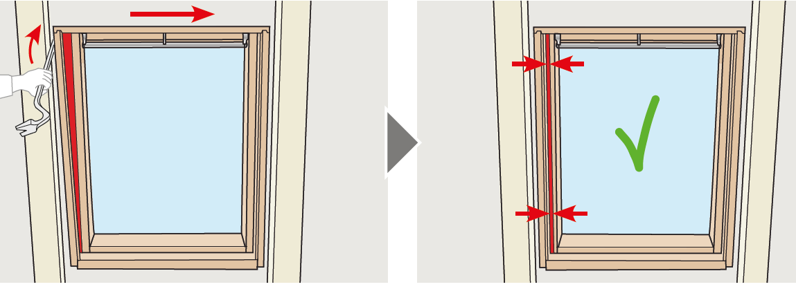
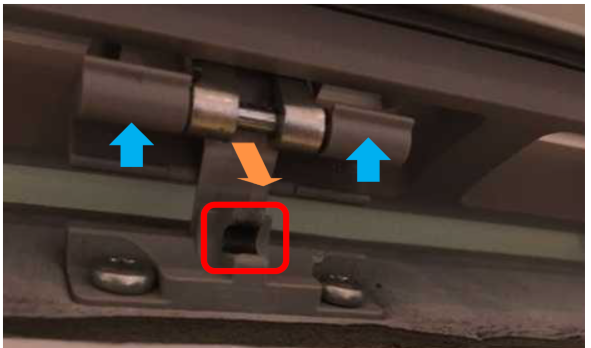
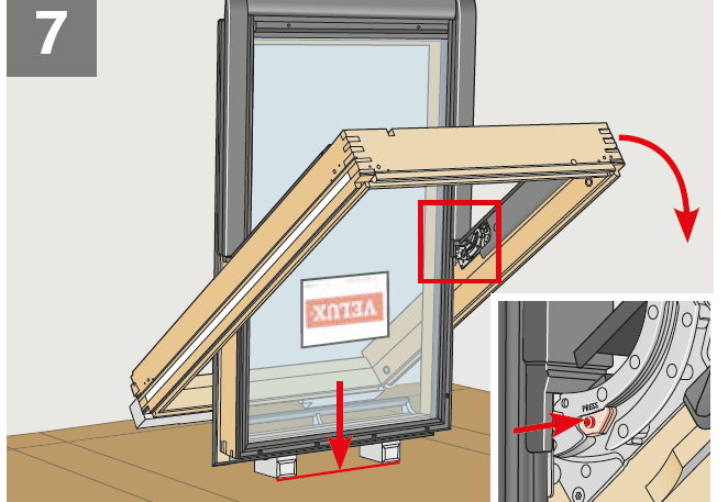
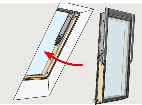
@Ed Davies for some reason my email kept refusing to forward it with the images, seems to have worked pasting it here. The latter ones are just from the instructions so won't be new to you, it's the catch detail that made me think I wasn't the first. --- Good Morning Andrew Thank you for contacting VELUX. We are sorry to hear you are having this issue with your new window. The reason for the issue is the fact that you installed the window as a complete unit. All of our windows have to separated when removed from the box as part of the fitting instruction. The vent bar handle should be engaged at this point to allow the separation. Our windows are not squared off at factory level and fitting it as a complete unit means that the sash may not be sitting squarely in the frame, this can cause other issues later where the window may not close properly. In order that you can get the other side of the vent bar engaged I have attached below the instruction on how to do this. Locate the one side of the headlock that is not engaged. Lift the headlock arm upwards away from the console clip, and pull forwards. This may require a bit of force, as you are moving the headlock mechanism manually. Once the headlock arm is pulled forward, close the ventilation bar fully. Open the ventilation bar, and the window will open as normal. [Img1] We would strongly recommend that you follow the fitting instructions for squaring the sash and the frame. Please see snap shot below form the fitting instructions. [Image 2-4] Please do not hesitate to contact us for further assistance.

-
"Normal" size ones are about 6-7m as I recall, though you can get larger. The major issue with using one to work on a roof or above a surface though is it's really awkward to work at the bottom of the basket because the floor, kick rail, guard rails get in the way. So you might be able to get the bottom of the basket against the roof surface, but not be able to do much when you get there. They're good for working on a vertical surface or underneath a ceiling.
-
I'd say import and trace. Raster to vector will probably give you a lot of artifact lines around the flash flare, wood grain, etc which you will have to tidy up by hand, and will probably treat the curves as lots of very short lines (which may not all quite meet due to shadow effects and approximation). I think that would all have to be tidied up before a CNC production. As it's a fairly simple shape, tracing it with straight and spline line sections will probably give a neater result more rapidly and, as you say, allow you to make it symmetrical.
-
Can anyone turn a pdf into a CAD for me?
andyscotland replied to Powerjen's topic in Surveyors & Architects
I remember once taking a show into a venue and the set didn't fit round a couple of pillars sticking out from the wall. This was a surprise, as our designer had carefully overlaid CAD drawings of all the venues on the tour to make sure it would work everywhere we were going. Turned out the designer had converted the CAD from a PDF the venue sent so he could do his overlay. That PDF had been drawn in CAD by a keen work placement who'd helpfully imported and traced the venue's original scanned pen and ink drawings to make them look "more professional". He hadn't had time to re-survey anything, though to his credit he also hadn't dimensioned anything. Our designer had seen the main width and depth of the space matched the tech spec and assumed the rest of the drawing was to scale... Sadly professional indemnity insurance is fairly uncommon in the theatre, and wouldn't have paid out by that night anyway. So we made some "adjustments" with a saw and a Glasgow screwdriver...