
Nickfromwales
-
Posts
30353 -
Joined
-
Last visited
-
Days Won
297
Everything posted by Nickfromwales
-
Find out the lowest typical heat load first, eg can the UFH only run when the rads are running? If so, then the system has a degree of energy buffering via the water volume in the rads which would only require as little as 25L buffer volume for worst case scenarios. If the UFH is to be able to run independently, then the requirement increases quite a lot. At that stage you could be into as much as 50-100L of buffering to provide sufficient 'energy run-off' for a scenario where just 1 or 2 UFH zones may need heat, but the boiler is still going full chat as it still has a call for heat signal. You really should not be fitting the buffer in the cold attic, that will just lose the residual 'wasted' heat from running the buffer. Instead, could you fit it in a cupboard or airing cupboard? It would be far better on the ground floor to use every ounce of waste heat advantageously.
-
Get a couple of 12.5mm cement boards, cut them to size and cut out a generous section for the trap. Then set those in on a bed of tile adhesive, make a load of piers rather than full solid bed, to match the pitch of the underside of the tray. Leave to cure. ( Rapid set makes this a race against time, so any novice should use standard aka extended set flexible adhesive and just accept the 24 hours between visits ). Set the tray onto as full a bed of flexible adhesive as is possible, and tap into place with a rubber mallet, lots of small taps, and level off. When the tray has cured, 48 hrs from the get go, final fit the trap etc and test with a hose. Make a 100mm deep dam of sand around the tray, flush to the topside of the tray, leaving just an inch or two gap at the outer edge / corner. Make a funnel out of stuff cardboard and get some builders leveller ( fibre impregnated self levelling compound ) and pour the entire void under the tray full to where it overflows the top of the sand dam. That will fill the entire void under the cement boards and also encapsulate the trap and pipework. Use expanding foam to seal around anything like final waste connection / gaps / cracks where the SLC could weep away, most importantly not into the waste pipe, so before pouring you must make sure all waste joints are rock solid!! Once done you can park a car on that.
-
You mean all pipes connecting TO the stack being replaced? If so, then fit a strap on boss to 50mm waste and pick the bath and basin up independently, as high up as possible. Problem solved for the bath and basin then, but issue could still exist for the WC with that then having the water sucked out of the throat and the bad smells migrating to that. Do you have any idea where this soil pipe terminates / pics of stack above WC.
-
Done by gods own hands there ma’ boy. ?
-
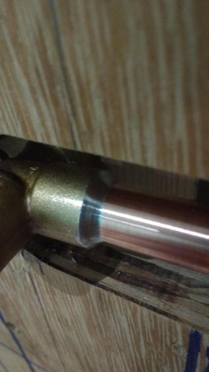
Yup. That’s what I do if I can get an end feed one. Lose the nut and olive and solder in. ?
-
Lose the compression fitting and buy an end feed one instead. With the leverage from the arm you don’t want anything there that is susceptible to eve the tiniest amount of movement. The compression fitting is a weak point.
-

Old plumbing methods, ventilation.
Nickfromwales replied to ash_scotland88's topic in General Plumbing
Example of basin trap -
Old plumbing methods, ventilation.
Nickfromwales replied to ash_scotland88's topic in General Plumbing
That’s an early example of air admittance, and we’d need to see the whole foul system to say that provision doesn’t need to be retained / observed downstream eg after a modern refurbishment of the bathroom(s). If the small bore waste pipes fall vertically for anything more than a metre or so, air admittance ( anti-vacuum ) traps would need to be installed to allow this function to ‘live on’. -
Can you search the MCS register?

-
Formulas are “not my thing”. I got these based on the manufacturers recommendations and a bit of practical knowledge from being on the tools for the last 25+ years or so. The acc will acclimatise to the peak static pressure which is attained around 03:00-04:00 hrs, and then decrease in effectiveness throughout the day. A second ‘peak’ will be late morning which should see you storing a very useful amount of free energy for use at typical bathing times eg mornings and evenings. I start out with an elevated Pre-charge pressure and then drain / refill / adjust / repeat until I get satisfactory results ( sufficient volumes of stored water ). I gave away my scientific calculator many moons ago, to someone who would get more use out of it Everything I’ve fitted to date either met or exceeded expectations so I’m happy to assume I know enough to offer useful advice here. With as good a cold mains as 4-6bar static, 30% would be due to an incorrect design / sizing etc. You could likely get up to 60%+ but I wouldn’t recommend cycling the bladder more than is required so as to promote longevity. Yes. At 3 bar the flow rate will be strangled slightly, so the second PRedV is absolutely essential to allow max potential at source ( to get the big L/p/m flow rates whilst capping the incoming ( pre balanced ) pressure to a constant manageable level. Not fitting that is not an option afaic.
-
In a nutshell, yes. Performance improvements with as little as 200 / 300L acc's are significant. With your stats this should perform extremely well, taking into consideration the preparatory works you've done with correct ( over sized ) pipework etc which already puts you in the best position to integrate one of these. You need a PRedV on the incoming cold mains and have that set to 4bar. Then have a 28mm 1/4 turn lever ball valve ( full bore ) to isolate the accumulator. Install a drain off cock in between the acc and the 1/4 turn valve so you can service the acc without turning off the water to the house. Set the pre charge to 2.5bar and allow the system to equalise with the 1/4 turn valve fully open. Once equalised, shut the 1/4 turn off and fit a hose to the drain off cock. Have a 10L container or similar vessel on the end of the hose so that you can keep filling that to record the amount of stored water, discharging the acc until empty. For a 450L acc you should be getting a minimum of 200L of water stored in it. "will it allow both showers to operate at full blast until the accumulator depletes?" Yes it will. Deffo. Plus it will also support any other cold mains dependant outlets simultaneously; WC's flushing, appliances filling, etc. Biggest mistake folk ( and some 'plumbers' ) make is having the outside tap come off the acc associated cold network. Somebody washes the car, showers conk out.The OS tap 1000% must be before the single check NRV at the incoming cold mains, so it gets fed off the supply aka 'rising' cold mains and NOT the 'artificial' mains you have created inside the house with the acc.
-
Excellent news that your new guy is on point You're very welcome.
-
No silly questions here mate The more questions you ask, the less things will have a chance to go wrong. You use a cold mains accumulator. Size of that is critical otherwise it won’t suffice. An accumulator is basically a big rubber balloon inside a cylinder which uses the force from the static cold mains to ‘charge’. The acc will typically hold 50%, or less, of its stated max volume so you need to double the size of the acc to get the required stored energy ( water held against its will at pressure ). I’ve installed loads of these with fantastic results, and there’s no pumps / mechanical / electrical parts to go wrong. The rubber ‘bladder’ does deteriorate over time but that rate varies massively dependant on how the bladder is cycled. Design of pipework / sizing of acc is everything, but relatively easy to estimate tbh. It’ll be very easy to put them in the basement, and for what you’re asking you will need 2x 500L most prob. A survey of the cold mains would be the first port of call, to see how much flow and static pressure you have available before any more discernible advice could be given. Pulps and break tanks would be for a much larger installation like a nursing home / small hotel / B&B etc IMO.
-
+1
-
Do a plan for routes for new CH pipework throughout, and hide it in the voids. Continuous runs of Hepworth aka Hep2o insulated with 25mm wall Climaflex pipe insulation will bend around corners and weave in / out of studwork / other obstacles. Far reaches can be in 15mm ( servicing 5 radiators max ) and then it needs to jump up to 22mm. Several 22mm runs can be spurred off 28mm primary flow and returns but it needs a bit of thought / planning. 2 "system" boilers would ( can ) feed into a low loss header, pumped by their internal factory fitted pumps, and from the low loss header you simply pump away to the 28mm primary's. You can also have the low loss header with multiple 1" pairs of outputs which could have a domestic pump on each set of 22mm primary's. As said, it depends on the design and layout and how convoluted the pipe runs would be.
-
Just remember that all the penetrations ( sockets etc ) need to be detailed accordingly eg foamed behind to stop air movement ( draughts ).
-
For this property I would seriously consider a twin boiler setup to run them at reduced duty. They’ll be able to kick in in parallel to heat the place from cold, and idle accordingly when getting close / at target temps. Being reliant on one boiler for a large dwelling, and for both heating and DHW is a risk when it’s one large boiler. If you install two, you have 100% redundancy / aka fail-safe.
-
Random internet grab; Link
-
Ardex A38 dry screed can be ceramic tiled in 4 hours. Cementitious tile adhesive is completely different to the type of adhesive that the Amtico layers will use. There is an even quicker drying dry screws available, but I can’t remember the bloody name of it. I’ll ask my mate, he’s my got to screeder ( who will travel btw ). He laid @Russell griffiths screed. PM him if you want a reference. Top guys. You need to petition the fitters to find out what they’ll use before getting any more advice based on unknowns Ask questions about warranties if laid on liquid screeds vs dry screeds etc
-
@Robert Clark I assume you’re referring to Amtico aka LVT? ( Luxury Vinyl Floor ).
-
Understood. That means they are for “auxiliary” heating then eg supplemental Firstly you shouldn’t tile directly to a wooden substrate. I typically use a binder layer of 6mm plywood, glued and screwed at 100-120mm centres, and then flexible tile adhesive over that. If you score the caber deck then you may get away with using something like Bal Superflex, which proclaims its ability to negate a decoupling membrane. That stuff is good, but expensive. If it were me, I’d want a minimum of 6mm insulation board under the UTH, but in a near Passiv / PH it’s quite academic tbh as these dwellings tend to sit at an extremely acceptable average ambient, and the tile heating will be strictly a comfort thing vs providing any ‘heating’. With the insulation boards you’ll be able to time this to come on as little as 30 mins prior to you using the room, but if it has to heat the substrate also, then you may need an additional 30 mins or more to achieve the same result.
-
That's going to cost a few £££ to run. What about radiators? +1 to fitting a pocket for the probe, that's standard practice.
-
Forgot to say you need to depress the pin to allow flow when the system pressure is up. D’oh. You’ll hear the water rush through and that needs to flow for about 3-5 mins. Air should be visible coming out of the hose with water, which will then eventually run quiet.
-
Not quite. Shut the system down and turn the power off. Then, take the actuator head off the loop in question. Then use the filling loop to pressurise the system to 2.5bar. Open the drain off so water is free to leave via the return of the air-locked loop, and, before the pressure bottoms out at zero, you open the filling loop so you keep blasting cold mains water through the loop and out to drain. That should have enough velocity to blow the air out and have the loop completely occupied by water only. Shut the drain off and close the filling loop simultaneously so the system pressure stays above 0.5-1 bar, Power back up and check for flow ( heat ) and let us know the results.
-
Does the return pipe get warm as well as the flow? If not, it’s air-locked.