Leaderboard


Popular Content
Showing content with the highest reputation on 09/04/17 in all areas
-
I'm sticking this here as I've been asked the question via PM, and rather than just give an answer to one member, I thought it might be more useful to stick the answer somewhere were others can also read it. Back when I was first looking at doing some rough "what if" type comparisons, between different build systems, windows, insulation and airtightness levels etc, I wanted a fairly quick way to be able to change one element, say the wall U value, or the efficiency of the MVHR system, and see what impact it had on the overall heat loss of the house. This model was never intended as a substitute for something like PHPP, which is very comprehensive, it was just intended to give a rough idea so that I could see the scale of some of the changes, and work out where best to spend our limited budget. Having written the spreadsheet for our build, others expressed interest in using it, so I tidied it up and let others have a copy. Because lots of people seemed to want to use it, and also because it generally seemed to give results that were within 10% or so of more complex models, like PHPP, I put a copy of the spreadsheet up on our website, as a free download: http://www.mayfly.eu/wp-content/uploads/2017/01/Fabric-and-ventilation-heat-loss-calculator-Master.xls This post is a set of very brief instructions on using this spreadsheet. First some health warnings. It was never intended to give an absolutely accurate prediction of heat loss, and as such it takes no account of solar gain, wind or incidental heat gain from occupants and appliances. As a consequence it is generally a bit pessimistic, in that it will usually tend to slightly overestimate the heating requirement. This is not necessarily a bad thing, as it can be useful to have a bit of heating capacity in reserve for exceptionally cold weather. To use the spreadsheet, you first need to gather all the data needed to complete the white cells. Most of this should be self-explanatory from the notes in each section. The U values, for example, should be the true U value of the component, including any additional thermal paths, so the window U value needs to be the Uw value, not the Ug value, and the floor U value needs to be adjusted for any thermal bridging around the periphery. All the areas are the internal wall, floor and ceiling/roof areas, not the external ones. The model does not account for geometric thermal bridging at corners, but in a well-insulated house this effect should be very small, anyway. Some of the most difficult to obtain data can be the mean daily air temperature and the mean minimum daily temperature, for each month. This data is available for your location on the Met Office website, but posting a link seems a bit fraught, as the Met Office keep changing their website and this makes any link out of date fairly quickly. All I can suggest is that you work your way through the historic data on the Met Office website and find that closest to where you live. Once all the data is filled into the white cells on the spreadsheet, you should get some numerical data in the green cells, plus two graphs will appear. The graphical data is often the most useful. First, there is a basic heat loss versus outside air temperature plot (the Heat Loss Vs Delta T plot). You can use this to determine how much heat the house will need to maintain the room temperature that you put into the spreadsheet (it defaults to 20 deg C, but you can change this to whatever you feel comfortable with). The red line is the total heat loss, the other lines are there so you can see which elements are contributing the most to the total. If you want to know how much heat the house will need in order to maintain a temperature difference between inside and outside of 20 deg C (say a 20 deg C room temperature when it's zero deg C outside), then just go up vertically from the 20 deg C point on the horizontal axis until it meets the red line, then go across horizontally from this point to the vertical axis and read off the heating needed in watts. The other plot shows the heat loss per month, and this one can be a bit confusing, because, like the other plot, it takes no account of incidental heat gain, from solar heating, appliances, occupants etc. The best way to use this is to print it off and pencil a horizontal line across where you think you wouldn't have heating on. For example, If you turn your heating off in April/May and on again in September/October, then draw lines across at about the point where these dates cross the other lines and call that your "no heating" point. The mean heating needed for each month will then be the difference between those lines and the values on the plots. You can quickly work this out by just noting the amount of incidental heat gain, indicated by the pencilled horizontal lines, and then subtracting those values from the monthly values. Be aware that this is really a very rough estimating tool, as there will be big peaks and troughs in daily temperatures within those months that will effect the heating required. In most respects, the heat loss vs delta T plot is more useful for sizing a heating system. Hopefully the above should make some sense to anyone trying to use this tool.5 points
-
Cheap Wood burning stove. You have to be quick, not much time left on this offer price (will be interesting to see how much it goes up by when the offer ends) https://www.woodburnerworld.co.uk/kresnik-multifuel-woodburning-stove-45kw-13612-401468 I have ordered one and will be collecting it on a trip south in a few weeks. I am not suggesting it for a passive house but the one I am buying is to go in our static caravan.1 point
-
I just used plastic conduit and metalclad double gang sockets. Cheap, quick to install, and good enough protection for the cables in this application. It's not as if the conduit is likely to be hit by something like a forklift, where metal stuff may offer better protection. I did fit a bigger CU and add contactors for the power circuits. I have three radial power circuits, all protected at 20A, all switched with 25A DP contactors. The contactors are all switched via a common 6A protected supply, via two emergency stop buttons either side of the workshop, plus a DP illuminated switch by the personnel door, next to the light switch. This allows all the socket supplies to be isolated by either hitting one of the E stop buttons or by switching the DP switch by the door. My main reason for doing this is that there will be two milling machines, a lathe, metal bandsaw, mitre saw etc in there, all capable of causing serious injury. I wanted a way for me, or my other half, to be able to quickly isolate the power if there was a problem. The DP illuminated isolator on the supply to the E stops and contactors is there mainly as a way of just quickly turning all the sockets (except the electric door socket) off when the workshop isn't in use, as a fire precaution more than anything else.1 point
-
My Senco collated screwdriver and drill/driver is here. Beautifully packed. And in clean condition, everything included. For £120 inc pp I call that somewhere between good and very good even if I need to spend £40-50 or so on new batteries, and I think I can recommend the ebay seller, who is unfortunately not a tool specialist. . Ferdinand
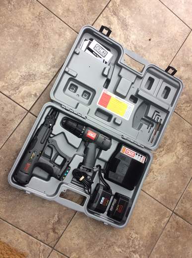
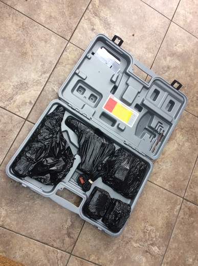
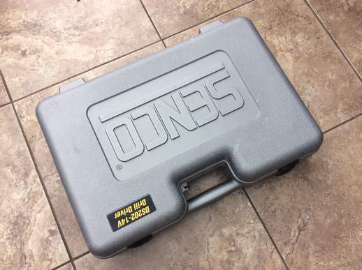
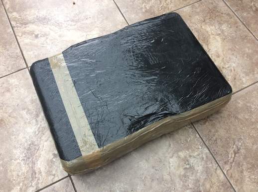 1 point
 -
You won't be able to see the wall in the garage as it will have a big flat screen telly on it and a beer fridge.1 point
-
Just a second voice on this issue. I can look at the roof we've tiled and point out every slate that I'm not quite happy with, the dormer I clad I can spot the two bits of timber that don't quite match. Everyone else looks at them and says "wow, that looks great" !!1 point
-
We've taken the plunge and Mr Vivienz has put the replacement thermostat in and, voila, it's working! Fingers crossed that this means no more cold showers for the time being. Thanks again for all the help and guidance, all.1 point
-
Removing trees from the site, prior to development, and as a required part of the development (don't mention the survey!) is a zero rated activity, so just give your tree firm a note with the planning approval reference number and you should be fine. If you don't yet have approval, then with luck you should just be able to use the description of the site that will be on the planning application, with your name, as evidence that the work is a part of a development that will be zero rated for VAT. Costs specifically related to surveys only are not generally zero rated for VAT, hence the need for caution in the wording!1 point
-
Snake oil indeed. I think we've discussed these before, but the fact they cannot defeat the laws of physics, despite claims that come very close to stating that they can, seems to escape a lot of people. Most electricity ends up heating something in a house, hot water in a dishwasher or washing machine, compressed refrigerant in a fridge freezer, domestic hot water in a cylinder or a kettle to make a cup of tea. There's a fixed equation that determines how much energy is needed to do this, and decreasing the voltage (which is what these things do) just increases the time taken, and that actually increases the electricity used, because the losses are higher. Take a kettle with 1 litre of water in it at room temperature, 20 deg C. To heat it to 100 deg C will take a fixed amount of energy, ignoring losses. That energy is pretty straightforward to work out, it's the specific heat of water x the volume x the temperature change, so in this case 1.161389 Wh/K/l x 1l x (100 deg C - 20 deg C) = 92.9 Wh. If the kettle element is rated at 2 kW at 230 VAC, then at an electricity supply voltage is 240 VAC the kettle element will deliver about 2.091 kW (2091 W). The boiling time is the energy required / power (ignoring case and evaporation losses for the moment), so will be 92.9 Wh / 20191 W = 0.046 hours = 2.76 minutes. If the supply voltage is then "optimised" to 220 VAC, the kettle element power reduces to 1.91 kW, so the time taken to boil 1 litre of water from 20 deg C to 100 deg C (again, ignoring losses) = 92.9 Wh / 1910 W = 0.0486 hours = 2.92 minutes. So, the kettle takes longer to boil with the "optimiser", but uses the same basic power to boil the water (so no energy saving). BUT because it takes longer to boil the heat losses from the kettle case and the evaporative heat losses will increase. At a conservative estimate, the kettle boiled with a voltage optimiser fitted will use around 5% MORE electricity than one without. The same goes for every single appliance that heats something, be it a domestic iron, or the compressor in a refrigerator, as well as all the water heating elements found in things like washing machines etc. How these rogues get away with sort of con trick is beyond me. I would have thought that they must be coming very close to breaching the advertising regulations.1 point
-
I use Purdy Elite brushes and Purdy rollers with a very short nap to give a smooth finish, which what we were after. I used Wickes Plaster Sealer which although expensive allowed us to seal without having to sand the plaster. The emulsion we used was Brewers Albany.1 point
-
I believe that while they had a profitable domestic side, they'd struggled with cash flow for a while on the trade side. But they needed the volumes from the trade side to support the workshops. I'd posted the following at the time:1 point
-
Just a quick update seeing as I had the camera on me. As always, not as much progress as I would have liked- I was away from the build for a lot of August, but it's good to come back to it refreshed. The painting is finally finished (that seemed to take an age), the WC is temporarily installed, and the woodburner is up and running- I'll do a separate entry for that, at some point. The overhead beams are now sanded back and sealed with Osmo Polyx oil- I'll use the same stuff on the windowsills. The trickiest part of doing the beams has been installing the spotlights, with some very careful drilling to feed the wiring through from above. These beams are tied into the rafters so any mistakes would just have to be filled as best I could, and serve as a reminder forever more. Today's task was to start on the flooring, which is carbonised strand woven bamboo. I am bonding this down so, again, little room for error. I decided that rather than start at one wall, I would mark a straight line up the middle of the floor, through the big connecting door, and then screw down a batten. This becomes my starting line and ensures that the flooring will tie up as it moves from bedroom to living room. I wa worried that if I'd started at the wall, then when the two sections of floor met up at the doorway I could find myself a few mm out. I have no idea if what I'm doing is common practise but it seems to make sense to me! I didn't get as far as bonding down anything yet today, as the floor turned out to be a lot dirtier than I realised, and I've spent all day on my knees with a sander removing blobs of paint and plaster. A few quid spent on some dust sheets would have been a good investment... oh well, I'll know for next time1 point
-
Wow, your plasterer has polished the shit out of that, it's like a mirror. I'd start by getting a fine sanding block, NOT loose paper in your hand as you'll scratch lines in, and take a bit of that sheen off. Painting over super polished skim is a pita and it doesn't take the first coat very well. Nothing crazy, just a good sweep over the surface like your waving the MIL goodbye after a 3 week long visit. . The best roller will be the one you can't buy, cos it's in the decorators van and has more miles on it than a taxi A good Harris roller with a medium pile will be your friend for the first two coats ( obliteration / mist ) and then a finer pile for laying on the finishes. 9" roller working quickly in small areas ( as the paint will dry in front of your eyes on rubbed, new plaster ) for the first two, and then onto a 12" roller for the finishes. Remember the finishes will be better quality paint so don't judge how the high-opacity ( HO ) stuff goes on as the rule of thumb for the finishes. The first coat of HO paint will dry quickly. By the time you get to the end of one wall, it'll be ready to go over again, so basically you'll be two-coating each wall in the same day if you get a groove on. That cheeky two-coaster gets rubbed down the next day quite heavily to remove the first roller marks, and any other bits of plaster or other surfaces grot. Don't worry about sanding through the paint, but, tbh, looking at the skim I doubt if you'll have much to do, it looks like a good spread laid that. After sanding, apply another coat of HO and leave to dry. Lightly sand that back and your then ready for the finish coats / colour. Spend money on a good quality finish paint and you'll get better results. Oh, and don't water down the HO stuff, trust me. When you coat the skim for the first time you won't believe how well it's covered even with just one coat. Don't try to get it covered uniformly on the first coat as it'll go a bit patchy here and there where the skim has been polished, which you'll see as you go along. Wait until the following morning to judge it, when the new paint isn't so opaque, and you'll be pleased with the results. Leyland HO brilliant white from B&Q ( look for the 20% extra free tubs ) and lots of it. ?. Oh, and the best painting tips come from those who HATE painting, i.e. ME! Cutting-in brush needs to be a 3" chiselled one, don't use anything smaller unless it's the nooks and crannies. This is the kiddy1 point
-
I'd recommend wetting the joint, say a metre at a time, and fill it as your go before it dries out. It'll help th filler to key to the FC and don't forget to force it in with some welly. Apply the filler once from left to right, scrape and reapply from right to left so as to fully saturate the gap and get good adhesion both sides. Don't leave too much excess on either. Toupret self primes . Another part of the process removed = more time swigging ale. ??1 point
-
I suppose this all depends on what finish you want. It is your plant room are you going to just slap a coat of paint on to keep it all clean or our you expecting a finish to match the rest of the house. Also is it taper edge board or square edge. If if you want a finish to match the rest of the house I wouldn't use anything but what is recommended by fermacel. I have installed 3 square edge boards in a scruffy boot room area we have and have just run a bead of white ct1 along the joints and painted, it looks fairly respectable and would be fine for a plant room/ boot room/ dog kipping area.1 point
-
I didn't buy the filler and I used standard Alabastine Filler from B&Q. It went over staples, screws and joints and it's never moved.1 point
-
Gyprock joint cement is fine prime with SBR several hours before1 point
-
And is a pita to sand back. Bearing in mind you don't want to work too hard removing it and risk marking the face of the FC. .1 point
-
I don't know anything about Fermacell but dot and dab adhesive dries pretty darn hard? Something like: http://www.wickes.co.uk/Knauf-Gypsum-Based-Plasterboard-Adhesive-25kg/p/1419331 point
-
I'd use Toupret filler. No need the prime, and it's really good stuff. Potato1 point
-
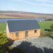
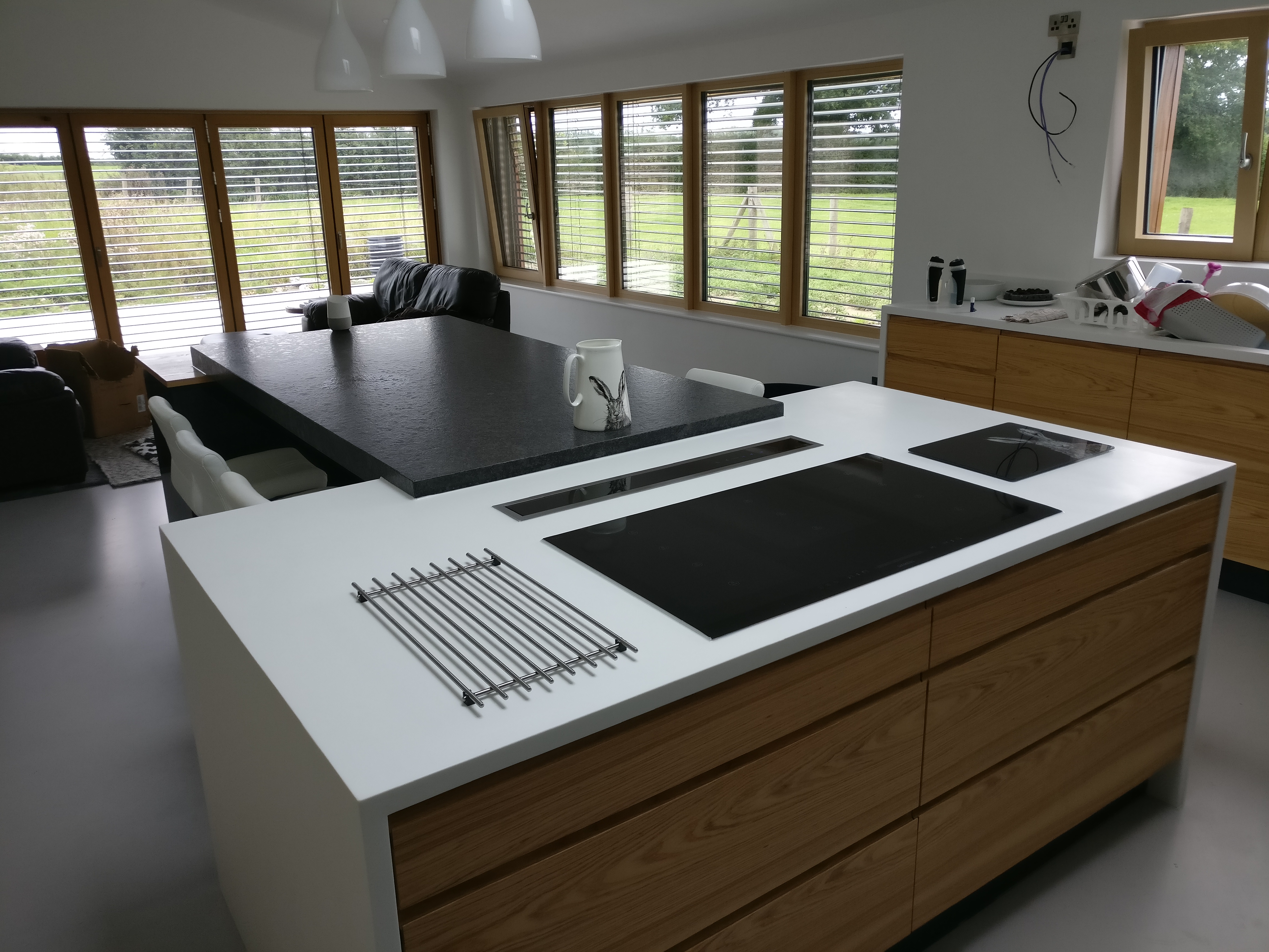
We went with a downdraft, recirculation unit from Elica. Very powerful, but a conversation stopper on full chat. Thankfully you seldom need to run it on full speed. Exhausts through the kick board under the hob unit, which isn't noticeable. Added bonus is it puts a physical barrier between the young family at the breakfast bar and any hot pans on the hob.

 1 point
 -
A proper "stop cock" is also a non-return valve, as the piston and washer is "supposed" to be able to float up and down when the handle is fully open, so preventing backflow that could contaminate the main supply. If you take a proper one apart, then you should find that the washer is fitted to a small floating piston than is located in a drilling in the part that rotates and is screwed down. The idea was that with no incoming flow, or under backflow, the little piston would drop down and close off the connection from the possibility of reverse flow. In practice I doubt that these old-design stop cocks ever really worked well as NRVs after a few years, every one I've ever taken apart has had the small piston pretty much jammed in place. Now you're usually required to fit a proper NRV (a double check valve) on the incoming supply after the stop cock for back flow prevention anyway, most probably because it's well known that the standard design of stop cock doesn't work as an NRV very well, as it's a very old design that goes back to the early days of mains water supplies. Given this, I'm not sure why there is still insistence that a conventional stop cock is used as the main isolating valve. My personal view is that a ball valve would be just as reliable (maybe more so) but a ball valve isn't a proper stop cock as far as the water regs are concerned as it's classed as a non-serviceable valve i.e, you can't repair it if it fails (barking mad logic, when you're dealing with a ball valve design that's inherently far more reliable, but rules are rules.............).1 point
-
Wales had to wave his boy off from school today as he's off for an 3 day outdoors jolly. Coach going at 09:30. Yay ? You shouldn't really be coming across tapered fittings in a domestic plumbing install TBH as they're typically only found in true iron fittings, but some weird and wonderful bits of equipment come as such, now and then, but rare. For BSPP the humble roll of PTFE tape is the weapon of choice. You can use fibre washers and wind the fitting right home, but I find the rotational force combined with compression of the two meeting ( washer and opposing mating surface ) chews the washer unless your absolutely spot on with the number of turns and torque applied. With PTFE you don't have to turn the fitting completely home, and you have to be pretty hard done by not to get a reliable joint. 13-18 turns of tape for rad valves Everything else needs a minimum of 21 turns, but if the dry fit is slack then don't be afraid to shove a good 26-28 turns on. What the fittings doesn't want will get displaced anyhoo but the number one thing to do, after applying the tape but prior to assembly, is to grab the taped fitting in a clenched hand and squeeze the tape down whilst giving a slight clockwise rotation ( turning the tape on in the correct direction is paramount of course otherwise it'll twist off as you do the fitting up ).1 point
-
This or one of these and reduce to 22mm from 28mm through this with one of these in the outlet instead of the 28mm olive.1 point
-
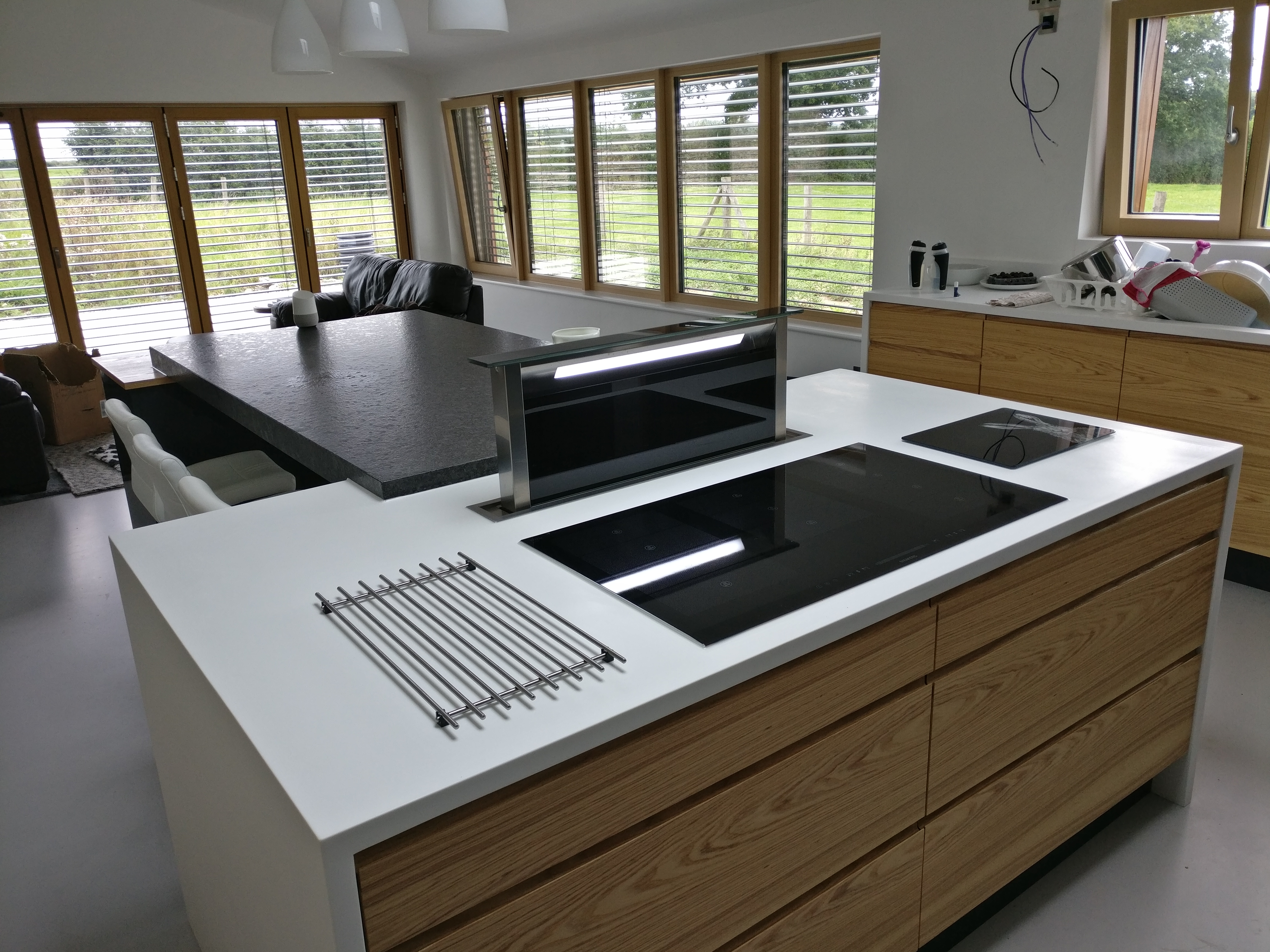
Thanks gents. I've made a start, got a dry pressure tester, just need to dig out my bicycle pump! I've soldered the manifold sub assemblies - where the cold manifold supply bridges over to the middle manifold (where the mouse is) , I'll be putting a compression Tee to make it easier to join. I've just used 22mm to all the manifolds - the left most is the hotter supply for showers and bath, the middle for basins at a lower temp and right most cold feeds. All supplies are heading through the floor space as the plant room is upstairs. The red arrow will be roughly the level of the UVC outlet with min 500mm distance.
 1 point
 -
A lot of this makes very good sense, Terry, but you (and I) have the time to do things this way, for our own convenience and peace of mind. Someone making a living from it has to do the job at an affordable price for the customer, and as the saying goes, time is money. The electrician I used for the house wiring was bloody good, but did think that I was going a bit OTT with some of the stuff I'd specified, and even some of the work I'd done before first fix, like fit loads of backing boards wherever fittings were going, all set to the right depth to either set the boxes in the right place or be dead flush with the rear face of the plasterboard where things like lights, pull cord switches surface mount control units etc were going to be fitted. I can understand why, as I had the time to do all this stuff in exactly the way I wanted it done, a luxury that someone making a living from it wouldn't normally have.1 point