
ProDave
-
Posts
30861 -
Joined
-
Last visited
-
Days Won
427
Everything posted by ProDave
-
As there are only 2, disconnect the link wire at one end. Then you will know which one is going off as it won;t trigger the other. What make and how old? It might just be time to replace them. Before anyone asks, I only ever recommend Aico smoke alarms.
-
Yes, the same sort of greenwash that says burning trees is good.
-
We had a granite worktop installed by Stone Source in Inverness. They gave me a few minutes to fit the tap into the worktop before they then bonded the undermount sink to it.
-
I suspect most of us (well me at least) just start on the mid speed of the pump, and if it all works well, slow the pump down. My aim was to run the pump at the slowest setting (quietest) that would deliver the required heat to the house. Having first changed the cheap noisy pump for a Wilo.
-
Nothing to stop you buying your own electricity meter and fitting it AFTER the DNO's meter as a check meter. I have one, but wired backwards to record how much I export. Some of the cheap clip on wireless ones are useless for me at least, as they can't differentiate between imported and exported electricity.
-
 Block up and completely seal the hole you made, otherwise that will be letting heat out.
 -
Okay so block and beam floor. What insulation was placed on top of that? Do you have a picture of this insulation duvet?
-
What exactly is the floor make up, including this duvet you talk about? A timber suspended floor needs ventilation. But if the floor structure is built properly the heast lost through the floor should be no more and hopefully less than the heat lost through the walls. Did you have it built? If so do you recall much about the process? A lot of causes of excessive heat loss are poor detail, like for instance gaps in the insulation or an over large hole where e.g drain pipes exit etc.
-
Total Heating Total Control (THTC) Help
ProDave replied to ColinG's topic in Central Heating (Radiators)
The panel heaters would continue working and continue to be metered on their own cheap rate meter. What would stop working is the rate switching of the main meter, and the switching on of the storage heaters when it should be off peak rate. As that is all embeded in the suppliers metering, there would not be much you could do about it yourself. -
Which is why beyond the heavy stuff, many of us choose to do all the details like this ourselves. If you have the time and can tolerate a slower build, it is the easiest way to make a self build very much cheaper. It also means you can make changes as you go if you see something could be done a slightly different way.
-
Internal wall insulation and freeze thaw brick damage
ProDave replied to PaulBartSpears's topic in Introduce Yourself
Our new house is the first house I have ever had, where the external wall surface is cold enough (due to so little heat loss) for frost to form on the render on a cold night (and on the outside of the 3G windows) I do wonder if that is a contrubutor to the problems I have had (and probably not entirely fixed yet) with my thin coat render. My suspicion that if any wind driven rain can find an opening to get in and not run off, then it will freeze and cause issues. This is of course much more likely to happen in an exposed spot in the Highlands than in a sheltered spot somewhere less cold. I notice around here, not one single garden wall that has been rendered has managed to keep it's render for more than about 2 years. -
1 m planning requirement to be scrapped?
ProDave replied to sharpener's topic in Air Source Heat Pumps (ASHP)
Interesting about take up more in rural areas, that must be (the main reason I chose one) is no mains gas available. -
I wonder if part of the issue in this case was it is a bungalow? the most efficient practical building from a heat loss point of view is a cube. A bungalow will have a lot more roof and floor to lose heat than the same square metres of house over 2 floors. When I instructed our assessor to do the as built EPC my instructions to him were if it does not achieve an A, do not lodge the EPC, instead discuss with me what improvements I need to make first to get an A. It mase an A94 without needing improvement.
-
What's the best location for the plant room?
ProDave replied to LnP's topic in New House & Self Build Design
That does not just apply to a "plant room". The noise of a central heating circulating pump reverberates around anywhere there are pipes. And i made the mistake of routing the flow and return from the ASHP under our bedroom floor. If i were doing it again I would have taken a slightly longer route and put it under the bathroom floor instead. I would not say it is "loud" but when I want to be quiet, I want things like that silent. -
Since somebody mentioned Valspar, and this is a thread about recommending paint brands, then I feel it my duty to say DO NOT buy Valspar Decking Paint. You might expect being called decking paint, you would have a reasonable expectation to paint some onto some clean new dry timber decking in your garden and expect it to stay attached to the wood. Well I can say that it does not and the first winter of being rained on, it will start to flake off. Utter rubbish and certainly not fit to be described as decking paint.
-
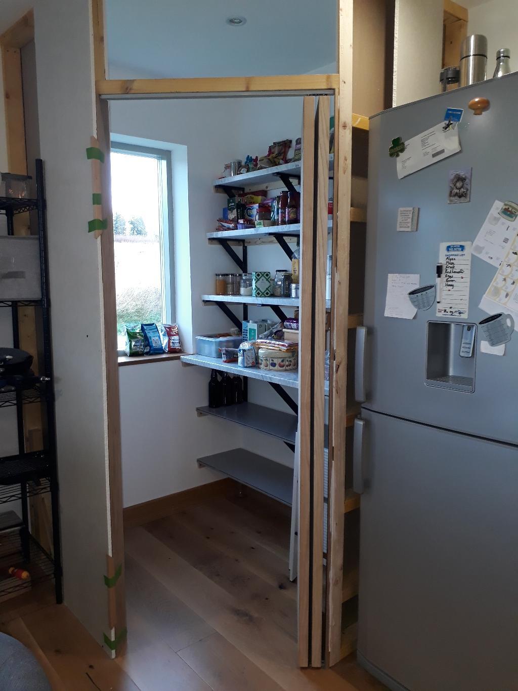
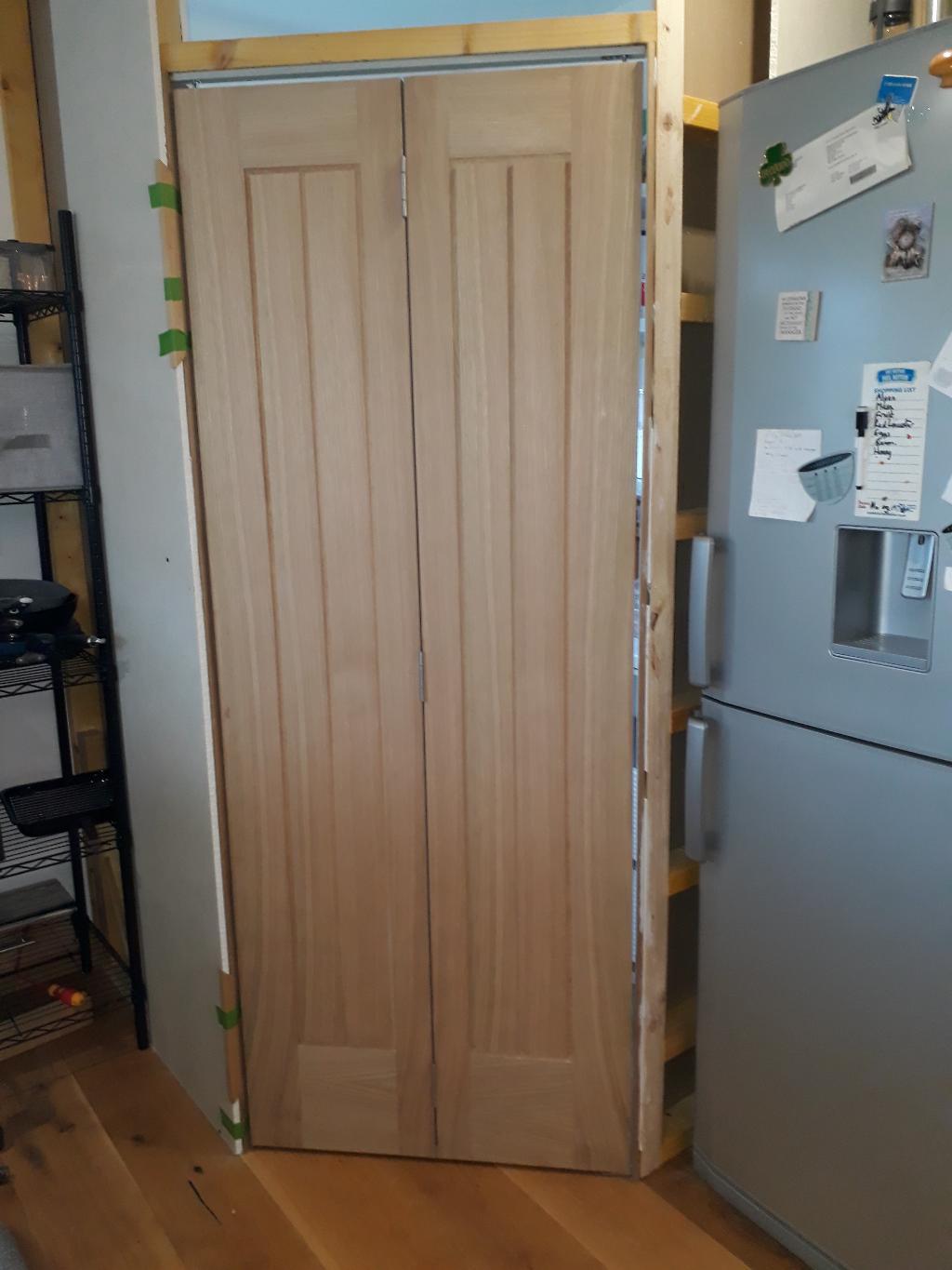
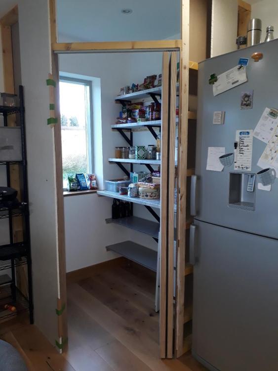
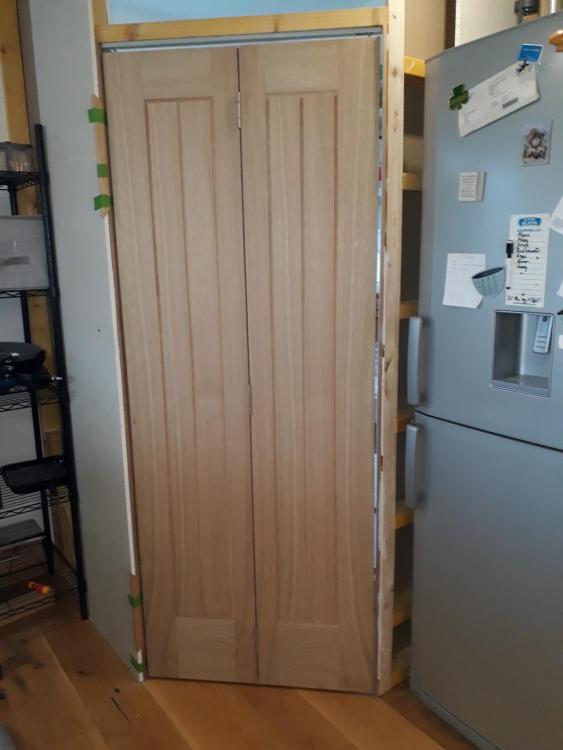
That's the main shelves finished, the bottom stone one now the right size and the two wooden ones at the bottm. And now all the shelves are in, the bifold oak door is fitted with the oak door facings both sides. And with the door shut Outside plasterboard and all the trims around the door opening to fit. That won't happen yet until we know what shelves we are putting on the left wall, as no doubt dwangs will be needed to the frame for those before the outside gets boarded.
-
Can't fix, won't fix...what's the alternative
ProDave replied to Thorfun's topic in Doors & Door Frames
The Scottish system is better, you would not get your building warrant until all such details are properly detailed and agreed and confirmed by BCO to meet building regulations. Then as long as you build to the drawings you should not have issues. -
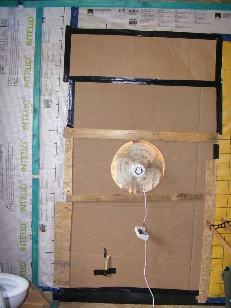
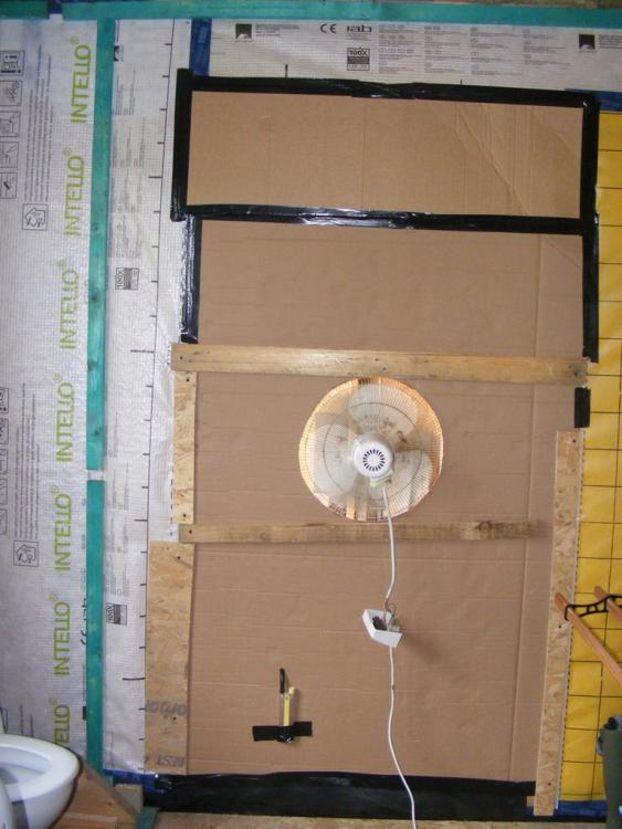
I did similar, a blower door on the door through to the garage, sucking air out of the house. It was very crude, big bits of cardboard, some duct tape, and old office desk fan and some strips of wood to support the fan. With the fan extracting air from the house, you can go round feeling or listening for any signs of air coming in. Also once the fan has been running for a while, a good test is to go and open a window or a door, if you are reasonably air tight, you will get a big whooosh of air enter as you open the door ow window showing the house had depresurised. Getting an actual measure of air tightness would be nigh on impossible as nothing is calibrated, but it gives you an idea of any air leaks you might have.
-
Heat Pumps work when installed correctly...
ProDave replied to Marvin's topic in Air Source Heat Pumps (ASHP)
Or if we still had a UK nuclear industry and we would be building our own designs. -
What's the best location for the plant room?
ProDave replied to LnP's topic in New House & Self Build Design
Like many I started down the "plant room" idea. I soon realised in my case at least it would not work. The only things in my "plant room" now is the MVHR unit, a pump and an expansion vessel for the heating circuit and some of the electrical controls for the ASHP. The ASHP is a monoblock so most of that is just in a box outside. CU is on the wall in the utility room where it is handy. HW cylinder is in an airing cupboard in the corner of a bedroom, positioned for short HW pipe runs i.e. at the centre of the points of use. Kitchen water goes direct from the cylinder, bathrooms (in the opposite direction) have a distribution manifold in the inter floor space again to get the HW runs as short as possible, anywhere else would have made the HW runs longer. There is a trap door in the ceiling of the utility room to access this. I am reminded of my plumber friend that put everything in the plant room and ended up with his hot water tank literally as far from the kitchen as it could possibly be. -
Can't fix, won't fix...what's the alternative
ProDave replied to Thorfun's topic in Doors & Door Frames
What did your plans approved by building control before you started specify? -
Planning application during divorce proceedings.
ProDave replied to albert's topic in Planning Permission
I used that to obtain planning in principle before I bought our present plot. With the agreement of the owner but I still had to serve the correct notice to him. Once PIP was granted we completed the purchase of the plot. -
Can't fix, won't fix...what's the alternative
ProDave replied to Thorfun's topic in Doors & Door Frames
Careful with that idea. Fire doors have to be mounted in fire door liners with intumescent strip in the right places in the door or the frame. I very much doubt a custom made bifold door set would comply. -
Was that a full SAP assesment taking ALL the actual details of the as built house, e,g actual UW values of each window?
-
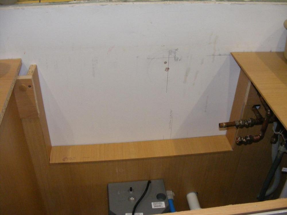
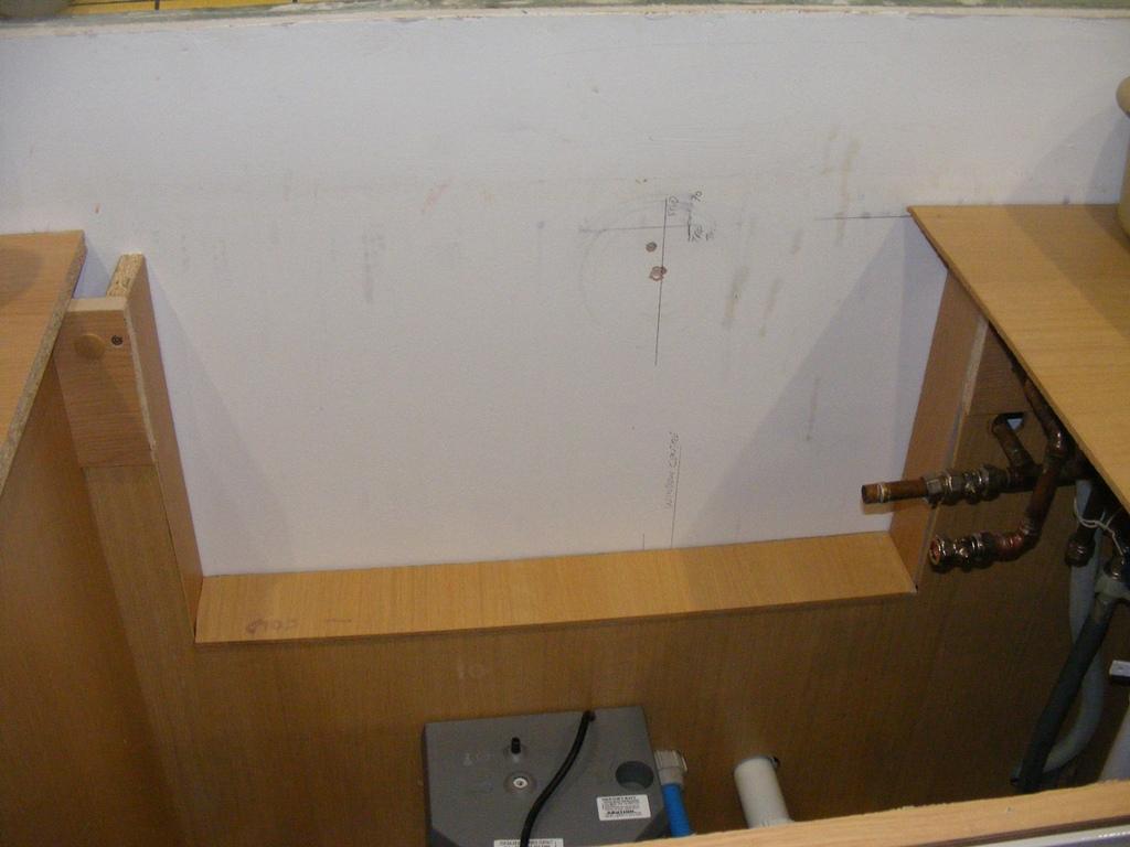
I anticipated the potential difficult access to the kitchen taps, so I butchered the back of the kitchen sink unit to open up a section of the back right back to the plasterboard to make future access easier.