Gus Potter
-
Posts
2342 -
Joined
-
Last visited
-
Days Won
29
Everything posted by Gus Potter
-
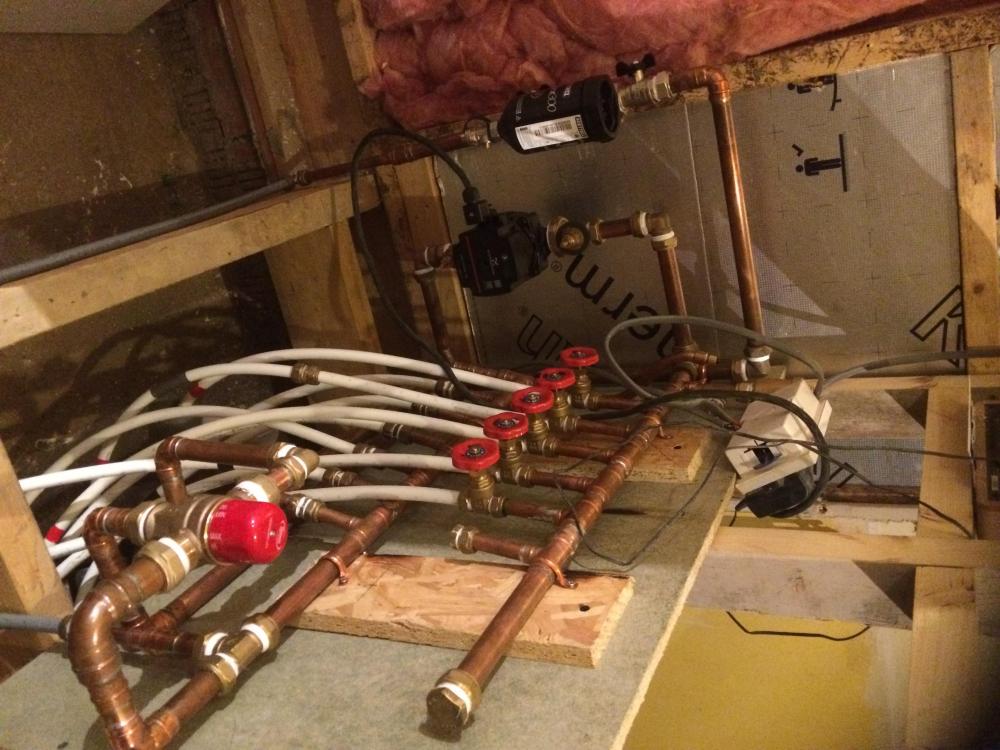
I'll chip in as the Philistine. I've said for years that all these complex controls on UF are a waste of time. They work fine for a few years, break down and then no one can fix then at a sensible cost. After while even the folk that have installed them.. yes even you BH folk then forget how they work and the nuances of your wiring up of the controls. I've designed a few UF systems in the past, always go for the simple stupid. Here is a knock up manifold made on my most recent house (photo is from 2020).. still working and have just extended it. It is a lot bigger now I have added more circuits and some basic controls. Now I know some may say you can't use gate valves.. I say they cost a couple of quid to replace if they start to weep. I know from experience that, as I did the same 20 years ago and times since, that this Flintstone stuff works, and folk can understand it. Lately I've added some extra electronic controls but these are not related to the pipework! Happy to take the pelters for my views.. ! You may think I'm bonkers but it was just something I know would work and made from fitting I had in my plumbing stock box. The biggy though is the blending valve. I have fitted an few of that type for other folk in the past and I know they are reliable. Also It's a 28mm blending valve so oversized to some repsects as it going onto 22mm pipework.. but my thinking is that any gunge will pass though it so I paid more for a bigger 28mm valve. My big mistake was to have some HIVE controls.. little did I know that I would have to keep updating the software and that if I move house I can't take them with me or some other shite like that. I learnt a lesson.. these are fundamental part of the house / structure.. DON'T trust them to third parties.. you could devalue your house a lot. Hi Marka. Before you start mucking about make sure your filters (nowadays mag filters) are clean and working ok. You probably have some kind of gunk / blockage coupled with those controls that we are all told will work for more than 5 years, the life of the system, like I stilll believe in Santa.. You don't want to shift the problem and say block your fancy heat exchanger on your boiler. Just before start to muck about incease the pressure in the boiler circiuit, say to 2.5 bar and operate the safety relief valve to clear that out and give you piece of mind. I would be tempted to isolate the manifold and connect a garden hose to the return (cold) drain cock at the RHS of the manifold, disconnect one loop at a time and back wash it.. You must back wash as if you get this wrong you'll really have a problem on you hands. You'll flush a load of crap out of some of the loops and it will make you feel good. Your average Plumber just can't spend the time to do this... you can! Now a few ball park sums: I think the pump you have can at top end with negligeable flow raise a column of water to about a 6.0m head. 1 bar of water pressure is about a 10.0 m head, thus your pump can deliver about 0.6 bar. As a bad case your hose pipe can deliver about 1.0 bar say.. this is should be enough to push back some of the gunk that you have loitering in the pipes. Try this first as it's a great feeling to see crap coming out the pipes. Connect it up again and see if it works. Now the thing with the hose pipe.. it gives you confidence as you know the pipes runs are clear. I tend when back washing to run the flow into a bucket so I can see how quickly each loop fills the bucket. If you know the loops are clear and now clean.. you have not just narrowed the problem down but given the system a good clean in the process. You can also time each loop to fill the bucket so you can then compare that to the flow meter in qualatiative terms. While you don't know pressure from the garden hose it allows you to compare flow rates against the hose pressure. If you want to get tecky the bucket flows should correlate to the differences in the flow meter readings. The main thing is to keep a note so you can then tie that back to any problematic sticky valves. I have mucked about with loads of these systems you have, flow meters / valves etc, for a few days they work and then break down again.. it will drive you nuts. You need to get it clean, then you can identify the sticky bits / valves which will give you the best chance of a long term fix. I'm sure you can do this .. but you need to be patient, set aside the time to do it and enjoy the investigation process. At the end you'll fix it and have a much better understanding of how it all works. If you are going to take things apart the use a non setting jointing compond to put them back together again. https://www.screwfix.com/p/flomasta-gas-water-jointing-compound-250g/7619J?tc=IT5&ds_rl=1241687&ds_rl=1245250&ds_rl=1249404&gad_source=1&ds_rl=1245250&ds_rl=1247848&ds_rl=1248151&gclid=CjwKCAiAp5qsBhAPEiwAP0qeJgeoDPCPpzi5pclPe4Z7WOvVn2L3w6jg_YEaMtCIxGTkJzNUkg39uxoCZGMQAvD_BwE&gclsrc=aw.ds To conclude.. your system probably has a bit of crap in it, each time you try and tinker you'll probably shift the problem somewhere else. The flow meters and complex controls are probably not playing the game. Clean it out yourself, have fun, and save loads of cash!
-
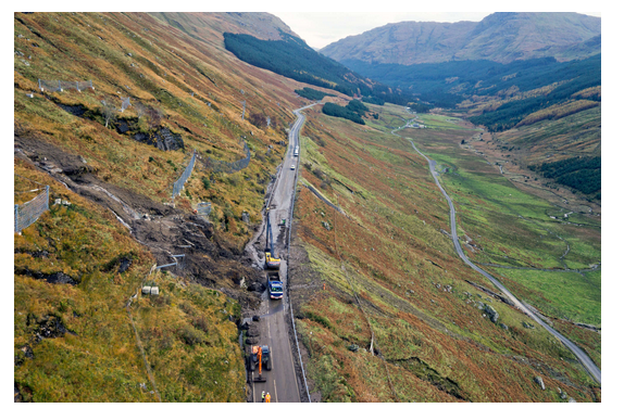
True enough but rights are shared in accordance with the deeds.. between the Highways and the land owner if that is the case. @ETC agree also and not least access and rights can be shared. The Highways may own one part to which you have rights, and you own another part to which they have rights. The main thing is to nip it in the bud early before folk start thinking they have timed out the planning system or start agueing the have some servitude (also called easement in England) rights. In Scotland we have a road, the A83 that has gobbled up tens of millions of pounds due to land slips and the delay has trashed the local economy.. The Scottish, they call themselves a government, read big town council,still have no solution. All the big Engineering Consultancies (some of these are the multi nationals have had a shot at fixing this) .. but see the little road at the bottom and the bit on the other side of the Glen away from the problem.. it belongs to someone who has clout and they are not going to let the amateures in Edinburgh run rough shod over them. @mid-ulster N ire One of the secrets of this is to lay down the markers, reference some research, provide evidence, contradict the evidence submitted by the applicant you are objecting to and then chuck the ball back in the Planner's court.. but essentially always ask for a response and give a dead line. You need to pin them down, make them run up the clock, cost them money and that concentrates the managers of the planners you are having to deal with minds. Make sure you put all this in writing and copy in someone "of standing". An easy way is to just bung you laywer a few quid just to keep the copies of the emails and let the Planners see you are copying them in.
-
Hope this helps. You starting point is the probably the Highways guidance. In Scotland we use the "Designing Streets" document. It's worth looking at this as it will help you navigate the English guidance. Without a detailed drawing it's a bit hard to comment properly but several issues present, I list the ones that spring to mind initially. 1/ Did the applicant miss represent the facts in terms of the drawings and statement of land ownership. 2/ What are the conditions on the approval. 3/ I suspect that they may be relying on achieving a visibility splay over land you own. You could if you wish plant or park something in the layby? I assume the Highways own what would be an extension of the verge, the first metre and you own the rest. Visibility splays often require a 2.0 m set back or a 2.4 m set back from the verge line.. so looks like they will need visibility over land you own. This could put a potential burden on your property in terms of maintaining a clear visibility display. If you don't and there is an accident then you could find yourself liable.. Look VERY closely at the visibilty display requirements. 4/ The two access' seem to be very close together.. normally they are much further apart. Again, this could put a burden on your property, not least in terms of maintenance but keeping say gravel off the highway. If the neighbours don't maintain their "bit" it could spill over and you get the blame too if there is an accident. 5/ If the site behind has potential for further future development potential then you don't want to lose control of the access.. as you could miss out on being able to negotiate a windfall payment or just stop any further development if you so desire. I think it's great idea to get on with your neighbours but the problem often occurs when they move on and you get a plonker moving in. @ToughButterCup did a post recently about what can happen if you don't nip things in the bud early, can be painful. I can't find the link to the post but other folk will know how. It's well worth a read.
-
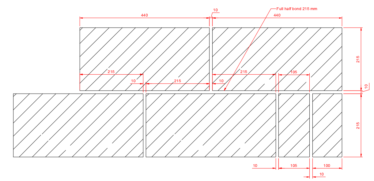
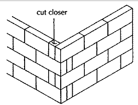
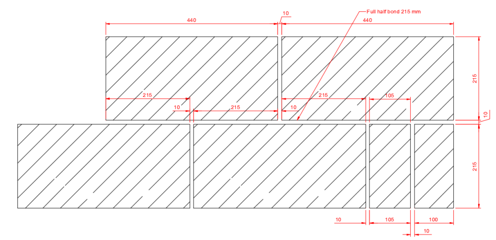
Nearly.. but someone has not planned it out right. My gut feeling is either the Architect or SE has not thought it through, or you have a brickie that it going to swing the lead and be even more lazy later on. Probably all are at fault by not talking to each other. Maybe the Architect, probably the SE by not positioning the movement joints in the right place and then not properly not specifying the bond required, mind you this is covered in parts of the BS 5628 codes, BS 8000 series for good workmanship etc. Blocks behave differently from bricks, bricks are shorter so the bond length is less but you have three brick courses for every on standard block laid on edge thus the bonding effect is enhanced with bricks cf blocks. Lucky you have the benefit of her intuition, I suspect there may be more to this and she has smelt "manure"? The below is the right way of doing it. Corners are essential as they can resist the bending forces in the wall which your SE may have designed for, a well constructed corner saves the day many a time.. but they must be constructed properly. For 100mm block the cut closer will be as below. For 140mm block the cut is a little shorter. The main thing is that you work out from the corners... the strong points of the wall and position any movement joints, debonding ties accordingly. You don't do a rubbish corner and hope the rest hangs in there.
-
Chewing the fat at my end. I like your train thought George. The big problem with big bolted space frame trusses is the bolt slip as the bolt ends up mostly working in shear and the second order effects that they generate. If you weld them then that problem partly goes away. But the cost rockets. Round about Glasgow they have loads of old bolted trusses, got one of these on my books at the moment. I'm trying to tempt you George into PM'ing me on your research and in return I hope to reciprocate. That is my offer, no point in mucking about. Gus.
-
Hi George. Can you let me know any more about this? For all.. when you get into truss design it becomes a very complex animal. Even more complex when you start to use cold formed cee sections. The nature of trusses often suggests long spans. If you have a truss with bolted connections.. these connections can often slip as they tend to work on a 2.0mm oversized holes and in shear rather than tension and shear on say a standard steel portal frame. This can lead to unpredictable behavoir. Once we enter this world as SE's we start to worry about things collapsing with no warning. Buckling of the frame, not just the individual bits but .. rafters / column interaction as a whole becomes a big issue. We call this in plane buckling where the whole structural frame buckles and falls down suddenly. Now this may seem like me being a bit geeky.. but if you are converting a portal frame barn shed in England, I think you call this class Q.. you do want your SE to understand what in plane buckling means? Ask them if they know about it. If they don't then point them to the SCI guidance and start to wonder if they are competant to undertake this kind of design. I have various bits of software to model structures. Some is main stream off the shelf that all SE's use. Some is more bespoke that I use when analysing complex problems. I have some pretty high end stuff for FE modelling, and cold formed steel design, don't often use it these days as my current Client base can't afford to pay for the analysis. It can take at least a week to set up a good FE model that you can present for other Engineers to verify. But always I do some hand calculations to make sure any computer model is on the ball park. You NEVER trust what the computer says and you NEVER trust anyone else's computer model, always check by hand to make sure the forces / stresses and material resistances are within the range you expect. A good SE / Architect / QS etc can look at things and say.. that looks odd.. if it does not look right it probably is not.. only a human can do that... smell the fishy stuff. Now AI is miles off being able to replicate what an SE does, Architect's etc are safe too. SE's, Architects spend many years learning how to make things work.. but a big part of the job is being creative and design things that are buildable.. AI just can't do that as it will always be behind the human curve. It won't know how to make things buildable unless we tell it how.. for every job and every different set of circumstances. Even if we could then market forces.. prices of materials, labour availabilty and local cost. The complexity of programming for a relatively small market I think will make it not viable finacially .. it ain't going to happen any time soon where AI takes over our jobs, mind you it it can make invoicing folk easier.. quite happy with that.
-
Airtightness tips for dormer loft conversion
Gus Potter replied to ectoplasmosis's topic in Heat Insulation
Examine the detail of this closely. It does work and often design this way myself in principle but use PIR between the rafters and an insulated plasterboard under with a vapour control layer. Under the tiles is usually a breathable (wind tightness) membrane, say Tyvek, part of it's function is also to resist wind driven snow. You seem to have that. But note.. the detail shows timber on top of the rafters.. NOT OSB3 for example as it is not vapour permeable enough. Usually I do something like this with a 100mm timber sarking board with a 5.0mm gap between each board. The timber sarking provides stiffness to many of the roofs I do so as it has a structural application anyway. Ideally we want to leave a 15 - 20mm gap between the top of the insulation and the underside of the sarking. This is an unvented space, not like the 50mm vented space you have traditionally. You could partially fill with Dritherm 32 in principle so long as you leave the 15 - 20mm space above it so long as that space is breathable. Don't know how warm it will be though so best check. I would also check the location of the air tightness membrane as you could get condensation on the underside of that... bad news. The bottom of the joists will be cold (they are a repeating bridge) so that is where you'll get bands of condensation. I would put the vapour control layer just above the plasterboard.
-
If you have masonry cavity wall construction then is there any potential for external wall insulation (EWI)? Often the gables are a good target area, lots of exposed masonry, less hard detailng around windows. Just check though that the space between the wall and the boundary will still comply with the regs if you added say 110mm of EWI + render etc. Also you need to check the detailing at the eaves and check it's not going to foul any other ventilation slots, say in a soffit for example. EWI can look unobtrusive if executed well, but if not.. Next would be the attic, lot's of heat lost here, is there enough insulation and can you get more in? I always like to start on the outside and see if there is a good line of first defense against drafts, is the mastic good round the windows for example. What are any soffit vents doing? .. are they venting say the attic as intended or are they encouraging other drafts and convection currents where they are not supposed to. Get up in the attic and check the eaves venting detail. The concept is that each layer of fabric provides layers of resistance to the air flow.. a bit like adding up the cumulative resistances of layers of insulation /materials to get an over all U value. This is a bit of a technicality but on timber suspended floors you need to have external brick vents at 2.0m centres to align with the NHBC requirements. Link is below. https://nhbc-standards.co.uk/5-substructure-ground-floors-drainage-and-basements/5-2-suspended-ground-floors/5-2-10-damp-proofing-and-ventilation/ You live in a windy spot thus a reasoned argument could be made to reduce the effective area of the ventilators. You could consider / experiment by partially blocking off some of the vents on the predominantly windward side. This would tend to reduce the air flow but as the leeward vents are more open it could reduce the air pressure under the floor which would mitigate drafts forcing themselves up through the floor. Now some folk may have a hairy canary at the thought.. but practically.. when we are doing the insulation calcs for suspended floor insulation we take into account exposure, the solum space and so on as the amount of air flow under the floor impacts on the performance of the insulation. You may want to open up again in the spring. Air tighness is a key, partcularly downstairs. But remember the more air tight the more risk of condensation if not controlled. In some ways you need to rule out the things that are not causing a problem. It could take you a bit of time but well worth being forensic. In the round it's worth thinking, cost wise is it easier / cheeper to add things compared with deconstructing parts and then replacing?
-
@George, elegant and practical explanation. As an aside a lecture of mine made his own Glulam beams, think they were curved. He was a keen woodworker and would get big hardwood logs off a Tree Surgeon. He a had one of these big chain saws that ran on a track and would saw them into planks, season them all and so on. I remember he wanted to do a contemporary type oak frame with these curved beams and had got a frightening quote. I would give it a go myself if I had the tooling, space, time and importantly have a use for them. I think there are about three ways off the top of my head of doing it. 1/ Set up a jig and dry fit everything using a long furniture clamps. Pilot drill and counter sink each plank. Then mix up lots of structural glue and put some overalls an a hat on. Lay down the first plank and hold in place. Next secret screw each plank to the next using plenty glue. The screws provide the compression to the glued surfaces. Scrape of the worst of the overspill, clean yourself up and wait. Once all has taken up get the belt sander / electric plane out and start finishing it off. 2/ Dry fit as above but pilot drill each plank as you go for an M12 / M16 rod say spaced at 400 - 600 centres at least the overall final depth of the beam. Here I think you need to use an oversize pilot hole to cope with the curvature , that you won't get right first time. Start fitting it all together. Maybe do 4 planks one day then another set the next day and use the rods and big washers to clamp them. 3/ Go for the more industrial look where you use a steel plate top and bottom to act like a big long washer and try and turn the beam into a steel / timber composite section. You can get standard stock flat plates at 6.0 - 6.1 m so for a long span beam you would need to couple the plates if going for long lengths. Could be a job @Onoff would tackle as he has the cad and fabrication skills? Technically things need to be CE marked for structural steels but as this a bespoke item then there could be room for manoeuvre to deal with the paperwork.
-
Trading off rooflight size vs supporting steel
Gus Potter replied to RatFloofing's topic in Skylights & Roof Windows
Agree with Kelvin, and as you know it could be a stunning space. My first thought was an Orangery type roof using the existing structural opening. This type of option cf a lantern can have particular features if done in timber that can't be so easily achieved with say aluminium profiles. Could fit well with the existing Architecture? There are diferent schools of thought in terms of number of say roof lights. One valid point is if you have a few huge panes of glass and one fails = costly to replace. This is something on my mind for my own house. When you look carefuly many of the glass unit manufactur's only guarentee the units for 7 years. If using the Orangery / pitched roof type lantern you have more scope to get opening roof vents in, not saying you can't get opening flat roof lights mind you. It looks a faily sheltered spot so you should reduce any risk of them leaking when windy after a few years of use. You may find the existing structure is ok, maybe needs a bit of beafing up. Probably the most challenging bit will be to get the flashing details sorted out as you have lots of awkward shapes around the edges of the flat roof. You'll probably be doing this anyway but look at doing the minimum and see if you can leave the existing flat roof as it is, just give it a bit of love. Then work you way up in terms of complexity vs return on appearance / improved insulation. -
Help! I need to Replace my GSHP
Gus Potter replied to Nially's topic in Air Source Heat Pumps (ASHP)
@Nickfromwales Jilly has forgotten more than we both know! -
88 new houses near Cambridge to be demolished.
Gus Potter replied to Temp's topic in General Self Build & DIY Discussion
It's because, I think you have many years experience as a Contracting Engineer, you are widely read, pragmatic, thoughtful but at the same time your head does not zip up the back, just like a lot of folk on BH. I enjoy BH as I would rather spend my time sharing what I know and I do feel that lots of other members feel the same, you give, receive and learn. @Declan pulled me up for putting BH at risk from spammers, I learnt from that. Sometimes it's the small things that matter, maybe the odd kick up the arse at times helps a lot. I'm in a slightly different space. My PI insurance covers me for free advice I give and opinions I express. That allows me to use my own name on Build Hub so long as I'm not daft. That is why I don't have to caveat every post I make. I pay a bit extra for free advice I give in my premium and that includes BH and other social media. I use my own name as I feel that if you can't stand by what you say then zip it. Also if you want to pipe up then expect some folk will disagree with you. If you can't handle that then.. zip it. Many modern journalists are a disgrace to their profession, they have no moral fibre, many are pathetic individuals who will sell themselves to the highest bidder, but we already know that. -
plant room Plant room Design
Gus Potter replied to openthegate's topic in New House & Self Build Design
Hello @openthegate Welcome to Buildhub. I can see you have spent a good bit of time crafting your post, it's appreciated by me. There is loads of info on BH, it's a friendly place. To provide a bit of context and further encouragement. I'm "in the trade" but I always learn something new when I log in. There are a load of other folk that are like minded, we want to share what we know and in return we want folk to reciprocate. This is a good site as folk will tell you.. I did this wrong and here is what went well and this is how I did it. Ok to kick off I've copied and pasted you post and added some initial coment inline with your text. We are still getting plans ready for the planning application. The house is going to be built into the side of a hill (with a gap of around 1.2m between the house and retaining wall.) It works out best for the views (and light) to have an upside down house with bedrooms on the ground floor and living areas on the first floor - where the front door will open out to the roadside. Like the idea of the upside down. The light on the North/West sides is quite limited and it makes sense to put the plant and utility spaces here. Agree but if using ASHP would you get more bang for you buck by facing into the warm prevailing wind from the Southerly direction? You want to extract warm air from outside.. is it a good idea to site it in the coldest spot? Attached is an my initial thought on the layout of the plant/utility space and where to place any ducts - the plan is go for a fabric first approach which includes ensuring all the external connections go through the slab rather through the walls to reduce the cold bridging. In principle I can see what your are doing. But in buildability terms when the pressure is on and the rainjis puring down the less slab penetrations you have the better. My rational for the layout is: ASHP on the north façade - placed the un-vented hot water cylinder much further into the centre of the house so the bath/shower/washing machine are all close to minimise the hot water pipe lengths. By moving this to the Utility space I though it would then be a sensible option to have all the water centric kit (washing machine/dryer/UHC/UFH) separate from the electrical kit. Placed the inverter externally to avoid over heating (as suggested by Jeremy H) - it is not in sun light and there is a cover over as well. If you post some elevations and a few more drawings you'll get a lot more response as it means folk don't have to second guess you.. it's much more efficient this way and then we can get down to the nitty gritty which is chipping to help you achieve a good buildable design at a sensible / affordable cost. In return you need to share what you learn... so all the folk an BH learn, it's not a bad deal and the Mods (who have worn every tea shirt going pretty much) keep everyone on the right track. -
Help! I need to Replace my GSHP
Gus Potter replied to Nially's topic in Air Source Heat Pumps (ASHP)
You're brand new Nick. I was wondering if you could retro fit a two and quarter inch Surrey flange to an unvented buffer tank, but was worried about the immersion fowling a modern coil/ plates My intention was to see what you could do as a stop gap to get @Nially over the Christmas holidays without having to burst the bank, use the existing cylinder and not do something that you can't reverse later.. or may be of use later. I'm still thinking.. you need to know where the coils / plates are inside so you can get the electric element in. Maybe if thing go wrong it would be advisable to order a 2" 1/2" blank plug and pretend it never happened. Fitting a flange of that diameter and getting a good seal I found is tricky. I used to do them when I was young but one mistake on cutting the hole and the cylinder is finished. Also the link I posted has a cork seal..I think. I'm not sure that would work with an unvented cylinder say potentially working up to 3 bar before the relief valve kicks in. Mind you in the old days I used Boss White and horsehair, still do at times (and is in my plumbing box) when working traditionaly on DIY but most now I use a non setting jointing compound for any threaded fittings. Yes I know an electric immersion is not probably cost effective in the long term but in the short.. it (the leccy) is about the cost of a crappy bottle of port in Surrey.. or in Newcastle 6 good sized bottle of Newcastle Brown.. or two bottles of Buckfast tonic wine in Scotland. Now ask do you know how much a stamp costs to send a Christmas card? -
88 new houses near Cambridge to be demolished.
Gus Potter replied to Temp's topic in General Self Build & DIY Discussion
On the upside, the Cambridge neck of the woods have challenging soils, not run of the mill stuff, exciting but you need to have your wits about you when entering this den of underground terrain.. not common bed time reading but for the keen. Cambridge lies roughly on the edge of the Gault CLAY formation. It's a thin band of a particular soil that stretches from Swafham, East of King's Lynn, thickens (on plan) aproaching Cambridge to Oxford, thins out and ends just to the east of Bath. At the Bath end it tends to be a bit less expansive as it is siltier and more sandy... but at the northern end (Cambridge end) is becomes a wolf in sheep's clothes. I'm trying to introduce some drama as it's nearly Santa time. The Gault clay can trip you up as when you dig as it can appear quite firm / hard. But when the weather changes is becomes a highly expansive soil. This can trip builders and designers up. It is quite a unique soil for the UK and in a thin and variable band so not often encountered. I can in some ways see why maybe design changes were possibly made late or on site. Now there may a be a bit more to this as Gault clay can also contain elevated levels of suphuric acid and sulphates that can attack concrete... and all that impacts on any steel rebar reinforcement in terms of rebar cover. It may be that the heave thing is exacerbated by the durability of the concrete and rebar cover. Maybe someone has said.. hey it's not just the heave thing but your cement content in the concrete / rebar cover is under spec for the soil type. Now that would impact on any concrete piling potentially. Anyway. At least no one has got hurt, it has been picked up, a lot of folk will have learnt some lessons.. the insurer's will pick it up and we the punters will pick up the tab one way or another. -
88 new houses near Cambridge to be demolished.
Gus Potter replied to Temp's topic in General Self Build & DIY Discussion
Not too late to become an investigative journalist! -
Help! I need to Replace my GSHP
Gus Potter replied to Nially's topic in Air Source Heat Pumps (ASHP)
Etiquette. -
That's a nasty number! Ok this seems a bit back to front but bear with me. It's a bit of a long read but hopefully you can pick out some bits that help you. You know what you want to build, how big it is as you have the plans. Do you know how you are going to build it? What are you preferred founds? What's the Architect's / your thoughts - strip founds, raft etc? From what you have we can make a quick approximation of the load the house is going to apply to the ground and how.. raft.. low pressure, strip founds a bit higher etc. Next is to go back to the beginning and find out exactly what the planners are asking for (you need to be reasonably confident you'll get planning in the bag before splashing too much cash) and really look closely at the level of information they actually require. On the plus side here there seems to be pattern for your local area.. the planning computer says no unless we can tick the boxes. You may be able access other reports for the area to see what approach does work and then how you tweak that suit you best. Now we look at what we need to know to build the thing in terms of geotechnical information. We have a mining element, will come to that later. Also potential gas from land fill and associated with that is contamination of the ground water. We would also check for Radon as a matter of course. The gas from the landfill. Risks are.. it forms pockets of gas under your house, explodes and blows your house up, asphxiates you in bed or gives you sick building syndrome (high mortgage rates can have the same effect) .. but the land topography and ground may make that impossible. Just because it is 500m on plan may not mean anything. Just say you have a railway cutting or other topographic barrier between you and the land fill.. how is the gas going to get to your house? If you can identify something like this and make a reasoned arguement then no need for gas monitoring? Gas monitoring is tricky to install and needs "monitoring" = cost thus we want to avoid if at all reasonably justifiable. The ground water contamination carries risk. Just say you have some to make a good story! Clearly we need to keep any contamination away from people and animals but also certain types of contamination will drive the selection of the type, grade of concrete and steel reinforcement cover if we are reinforcing the founds. Things like sulphate content, acidity and mobilty of the ground water can drive the concrete design and this would be associated with contamination at a shallow depth. Also, if you have a public water supply the supply pipework needs to be able to resist contaminated water (comes at a cost), and if you are going for a private water supply... well you really do want to know about contamination. I find the mining fascinating. I've done some jobs where we have bored for mine shafts and shallow workings on small sites where the Client was happy to fork out the cash.. the outcome was that we never found many of them.. but that is not to say they weren't there.. all I learnt was they were not where we drilled! I was convinced they were there at times on some sites but unless you absolutely pepper the place you can't be sure. In the round I often made the argument that on balance of probablity there was not a huge void under the structure, made some assumptions about the type and size of void that could reasonably be there and designed the founds for that. The mining. Now on the above we didn't just turn up on the day with a drilling rig. I carried out a really comprehensive (phase one) desk top study and spent at least a day walking over the site, the surrounding area, looking at the trees, the topography of the ground, and chatting to local folk.. who are often really helpful and sometimes will show you old photos they and their family have kept. Next is re examine the mining records (can be hard) and public available borehole records. I try and find any historic books on the area that maybe relate to industrial activity, old geological records. Sometimes you find nothing at all and sometimes you find a nugget of information that can save you thousands. Now you can imagine that I'm not going to do this for free! but there is good reason for this approach, it makes you think and by doing that you manage risk. All of the above gets coupled up with a typical search (historic maps, floor risk area, general mining risk etc) and info from say Ground Sure or other companies that provide these types of online data services. But the value lies in showing (and just knowing in your own mind) that you have followed the correct procedure in terms of identifying risk, what you do know, what you don't, there is the "what we don't know we don't know".. but life is exciting enough as it is. The objective of this is two fold. It allows me to make a list of all the things that need to be considered, then apportion risk and prioritise each of them. It also lets me plan the intrusive (investgative part) of the site investigation and make best use of the funds available to do that. The funds can vary depending on how much the Client is risk averse.. some Clients just don't listen enough to make their own informed decisions and regret later. To come back to the mining risk. As a quick over view there are a few different types of shallow mines you can encounter. Don't forget that more modern mines had ventilation and escape / ventilation shafts. Early mining acts for example 1862 prohibited single shaft mines. As a quick run down. From early times folk just dug up coal where it outcropped from the ground. Then you had say the Monks that dug bell pits, 12th centuary onwards. Ok a lot of these these have probably collapsed / settled a good bit but there are a few examples localish to me where you can see the depression in the ground from collapsed bell pits.. not for building on at sensible cost. Mind you, I have often wondered if I'll find someone who wants to dig it back out and make a bell pit basement. Jumping ahead you had drift mining.. they dug from ground level and followed the coal seam which is usually sloping. Later these were widened using say timber props, you have the pillar and stall method where they would leave pillars of coal, dig out the coal, chuck the spoil into the redundant bits and when they abandonded the mine they removed the pillars and let the thing fall down as they progresssivly left the mine. Laterally in some places they started using a method called long wall mining. Here they used a big machine to excavate the seam and just let it progressivly collapse behind them. This created a rolling wave of soil movement at the surface which damages houses. But the main thing here is this type of ground collapse happens quite quickly.. a few years, a couple of decades to settle in once the mine is fuly abandoned and the ground water recovers, which lubricates the particulates of soil, encouraging settlement. Older types of mining - some can take 100 years or more before they throw in the towel and cause problems at the surface. All the above relates to shallow mining in general. Deep coal mines tend to have many layers of rock over so the tiny extra bit of weight from a house is negligeable. Now the brief history story is nearly over. Next step is to try and identify where the coal is (if in Cornwall say then there is a lot of mineral mining but the same basic rules apply with a few tweaks), the way the rock and coal seams are sloping (they tend not to be flat and level and early miners followed the seams), how thick they may be.. and where the ground water lies. Now the good thing is that in a lot of the UK there is ground water extraction which tends to lower the water table. Many mines have been shut since the 1980's so the pumping has long ceased. Therefore the ground water level we see now is probably lower than what it was historically, give or take. This can give us the "worst case reasonable depth" of some types of mines. What kind of mining has possibly taken place in the past? If we can find a bit about the ground water average level then we could assume the Monks, earlier methods of pillar and stall were no deeper as they didn't have steam pumps say to get the water out. Many millions of years ago the part of the UK below the Highland boundary fault was well south of the equator before it joined up with the top part of Scotland to make the UK.. our island. There is more to it but for another day. The coal was laid down when the bottom part of the UK was tropical / sub tropical. Later though when we all got glued together the magma in the earth forced it's way up to create what we call magma (granite) intrusions / dykes. This hot material burnt the coal measures and these are often marked as "barren coal". In other words it's of little use. It is a wel known fact that barren coal measures were avoided by the miners. In places dykes can be quite closely spaced and are often identified in the records. Mind you you don't want one under half your house as they are nightmare to ecavate and cause hard spot which is problematic, not just for founds but getting drainage routes established.. Now if your site has say a high water table, some granite dykes then we want to look at that as we may be able to say.. hey this coal is barren / high water table so it probaly has not been mined... thus no need to indulge in expensive driling. Just be aware though. It's not just coal. In many parts of the UK they also mined fire clay and other minerals so we would need to watch out for that. All of the above is the phase one investigation, thinking and research. If you assume you are going to get planning approval in one form or another I would be inclined to plan the site investigation around gathering the information we really need to get the house built. I would try and avoid gas monitoring, drilling if possible (make a big saving) and spend a bit of the savings on maybe more trial pits, some porosity testing, gruond water (especially is you have a basement) to make sure you can get rid of the water easily. On the other hand if it turns out you do have a real mining / contamination issue then we need to know that as soon as possible so we can design for it at the outset and manage cost. It may be worth doing both phase one and two (intrusive investigation/ analysis) at the same time. Then tailor a report with plenty technical detail for the planning submission. Say to the planners, if there is anything you disagree with let us know. At the end of the day if we are going to design the structure to be safe and seviceable then surely that should satisfy the planners? I think the planners want to know that what they are giving concent for is not going to create a legacy problem. In some ways you are just a custodian of the house. Hope this helps a bit, keep us updated and all the best.
-
Help! I need to Replace my GSHP
Gus Potter replied to Nially's topic in Air Source Heat Pumps (ASHP)
Hi there. As a stop gap can you fit an Essex Cylinder Flange - 2.1/4" BSP F Brass to your buffer tank near the bottom? see link below: https://www.stevensonplumbing.co.uk/immersion-heater-mechanical-flange.html Then into that fit and electric immersion say 3.0 kW like below with a timer etc. https://www.screwfix.com/p/tesla-titanium-immersion-heater-14-/74662#product_additional_details_container Mind you that all sounds easy on paper but.. you need to know about the tank and in particular where the coil is located inside. Before cutting a hole in the tank I would phone the manufacturer, explain the problem and find out where they install a factory fitted electric immersion.. which they probably do from time to time. Now with a bit of care you can do this yourself.. if you take your time and use the right tools then you can get them to work.. @Nickfromwales could maybe provide some tips. I take it that the buffer tank is unvented thus it is a "pressure vessel" and as such the unvented cylinder regs apply. Anyway I'll let you mull that over, no need to say any more. If you make a good job of it then at least you'll have a backup next time your system breaks down.. merry Xmas ba humbug etc.. just kidding. On the upside if you later fit pv panels you'll have a ready made destination for the electricity you generate.. have a great xmas and remember that every cloud has potentially a silver lining! If you crack on it could alll be up and running ok ish for Santa. -
Any SEs in the forum? Looking for a second opinion
Gus Potter replied to ash_scotland88's topic in General Structural Issues
Thanks Declan, will not repeat error, appreciate the spamming. -
Detailing Wall-plate for 10° Monopitch....
Gus Potter replied to Mulberry View's topic in Insulated Concrete Formwork (ICF)
Hiya folks. I do like the ICF concept but we are self builders here, not McAlpines ect ( major Contrators) who have Engineers on site checking levels etc. It's self building and we have limited resources. Ok a few options considering what you have to work with. First is ICF.. you have been pouring all day..worrying about bracing and burst out, getting the compaction right and the concete coming on time, it may be raining and windy.. by the time you get to the top of the wall everyone is knackered on site.. the last thing you want to do and are just too tired to do is to finish the top off or start thinking about bedding in fixings. Don't even try to do this at the end of the day. I would keep the top of the concrete 0- 10mm low if you want to "go with the computer"... if you want to be pedantic... not my favoured option. You need to tie the roof to the top of the wall. You can use Simpson L brackets for this which are good for uplift and shear loads. For Posi joists you can introduce a vertical noggings /dwangs if not already provided to give you a nail fixing for the brackets. I would keep the concrete 55 + /- 5 mm low and then later bed and tie down at your leisure a traditional timber wall plate 95 x 45 C16 grade timber on that. You can get it level, fix it down easily and then you can get your expensive posi joists spot on level. I may come over as a philistine but I see this all the time where.. the computer drawing says yes.. but on site at the end of the day, messing about with concrete, with local builders the mood music is.. "NO CHANCE MATE" I know you can go on ICF web sites and the posi joist web sites and it all looks sooo easy on the computer.. but on the ground it is not so. The trick is to identify where things go wrong and actually design and plan for the "shit that happens" Cut yourself some slack.. keep the concrete low and introduce a get out of jail free card for youself by way of a traditional timber wall plate as above. This way you actually get more control over the quality between the two interfaces and design packages as you are able to adjust the wall plate height and at a push it's thickness youself.. you get a fresh start with the roof levels. This can be a bit more work but it it can avoid disputes which are really stressful.. you create a zone where you can just "sort it yourself" and you make a clear break point between the roof and wall work packages if need be. This is unique to the self build thing.. we need to often balance personal stress / family pressure vs the build. I see this and have in the past been a self builder so the above is based on my own experience. You know you have the ability so if you can apply that to make a clean break between the work packages / last lot of contractors it can help a lot. Some Contractors are great and you want to keep wqorking with them.. others it a relief to see the back of them (I'm being polite here) -
I think you are approaching this in the wrong way. You are trying to achieve savings buy the division of parts. Lets put this another way.. you can buy a car complete for £Y or the parts and assemble it yourself for £ Y.. but unless you know what you are doing Y will always cost you more than X. Get your SE in now to guide you as to how you marry all this up. I would charge you about £1500 quid to put you on the right track.. sounds a lot but I know I could save you much more and easily cover my fee. I know you may think this is a lot. But a good trademan will cost you £ 1.0 to 1.2k a week, all I need to do is save you a week and a half of labour and I'll have washed my face.. then think about what I could really do for you? I could give you pointers and you can play to your hearts content on your insulation.. we would discuss it all and if I thought you were making an error I would pipe up and say.. hey I think this is wrong .. what about doing it this way..that is good design is all about where we all work together. If you can find a local SE that knows the local contractors. If you have a basement then you are into tricky terratory. You could blow tens of thousands if you make the wrong play.. and that also means if you tell you designers that is what you want.. and if you are too cocky they will just give you what you want as it is your money! I love your space frame concept, @Kelvin has a stunning house with a space frame for example. Your passive house goal.. love that too .. your basement.. that is where it could all go wrong unless you get a handle on the SE design early on. You need an SE for example who is going to stand up to the TF designer, the slab designer and the basement designer on your behalf. What you are doing needs good technical support leaving you to make the fundamental financial and overall design decisions. I know you want to do your own thing.. good for you coming on BH as you'll get loads of free advice from folk that have been there, made mistakes and can tell you.. don't do this! All the best and keep posting.
-
Hi all. Eveyone get a like here. DRM, I like the simplicity of your model and saw your post popping up a few days ago. I've put a few numbers to everyone's suggestions regarding beam depths as a conservative first guess and made a few conservative assumptions (please forgive the typos / grammer as I'm off duty): 1/ You are probably going to put a lot of glass surrounding the courtyard bit and maybe a fair bit along the outside walls. All this means that we need to control deflections so we don't cause glazing problems and if we control the deflections usually the steels and connections will also be fine when we check that it won't fall down or blow over in the wind. 2/ Slab thickness. Concrete slabs are heavy things. Let's run with your slab thickness of 200mm for now. As others have said there are other solutions that may be more economic, provide more service space etc. In the round we will end up with a similar roof weight or a bit less. Budget on the really simple stupid for now and then we refine. It gives the Architect (maybe you) more room to be creative if they know the "worst case" at the conceptual stage. 3/ I'm also going to treat all your roof slabs as spanning in one direction rather than two. One direction span (not the pop group) means that you could use a structural B reinforcing mesh. Main bars in the span direction are thicker, the transverse bars control cracking of the slab and a few other things. We can make slabs thinner later if we make them span in two directions.. but we need to balance the cost / knock on effects if we do this... there is no free lunch in this self build world. 4/ I'm going to treat all the beams as simple supported and see what the later results are. When a beam is continuous over say a central column this support can attract a lot more load due to the beam continuity and that can impact on what happens at the bottom so you end up putting more load down the internal columns (can be up to as much as 40%) and foundation pads. Let's go simple stupid for now and see what happens. anyway very long beams are a hassle as you may need special transport.. and that often costs a lot..and they are heavy.. Always look at the cost in the round of steels.. too heavy.. too long and the cost to get them on site and handle can out weigh any clever SE savings. Also pick steels that everyone stocks off the shelf. 5/ I'm going to rationalise all the steel sizes so we can later see if we can get the best out of the stock lengths easily available. It also simplifies the connection design.. many other things that will drive the build cost down. Be aware that when you have steel beams with thinner webs and flanges it can really drive up the fabrication cost and these beams are not a stock item. Don't try and be clever at this stage loking for the lightest weight of steel as it will trip you up later. 6/ There are load of other things but let's do some sums. I'll work from the top roof covering down. Remember I'm sizing conceptually based on deflections, not strength design. I'm going to split up the loads into two components / calculations: The first are how much the beams etc will bend by when say it snows or folk are working on the roof and you introduce say pv panels.... call this the imposed or live load. The second is to see just how much the beams will bend by when all the self weight of the structure and the live load is applied. Lets look at some loadings you could have on the roof if you say live in England / Northern Ireland and benign parts of Scotland, Wales. I'm not going to touch on wind loads (that push the building sideways) as that is for another day. For all I'm going to work in kilo Newtons (kN) as units. 1.0 kN ~ 100kg to give you a flavour of what things weigh. Live loads on the roof prescribed by the design codes: Say typical snow load in England 0.45 kN/m^2 ( kilo Newtons per square metre of roof when looking on plan, straight down) Roof access load for maintenance 0.6 kN/m^2, in the design codes. The access load is greater than the snow load so I'm not going to consider snow load any more, particularly as the roof is flat and I'm assuming that there are not any higher buildings nearby that could dump snow on the roof. Pv panels.. say you have panels but want to put them on a frame to get the aspect right for best preformance 0.25 kN/m^2 Total live load = 0.6 + 0.25 = just say 0.75 kN/m^2 Live load ~ 75 kg/ m^2. Incedentally this number correlates to some of the old roof design codes. I use this when assessing old roofs for pv panels.. it's a funny world! Dead loads on the beams: Say a PTFE roof covering with some ply on PIR insulation. But we need to create some kind of slope in the roof to let the water drain. I'll play safe here and allow for a concrete screed to create the fall, say a cement screed or something that averages 50mm thick (say max 5400mm span with a 1:80 fall = 5400 / 80 = ~ 70mm of average screed required once you put the bells/ extras on. Average screed density + insulation + waterproof covering = 22 kN/m ^2 thus 0.07m * 22 = 1.54 kN/m^2 say 1.5 kN/m^2 as a ball park figure. Take the concrete slab as 200mm thick as per the sketch up model. The weight of this is the density of a lightly reinforced concrete (I'm avoiding a thin slab with lots of expensive/ complex rebar)* the thickness = 24 kN/m^3 * 0.2m thick = 4.8 kN/m^2. Note: I have not spent much time mucking about with the other loads as the concrete weight really is the dominant component. Now we need to put in a ceiling and some services on the underside. Allow say 25 kg/ m^2 ~ 0.25 kN/m^2 Add up the total loads: 1.5 + 4.8 + 0.25 = 6.55 kN/m^2 say 6.6 kN/m^2 ~ about 650 kg/m^2.. Now that is quite a lot if you compare that to say a timber flat roof with say posi joists which will clock in at a lot less.. but I have a light weight warm roof on part of my house and you can hear the birds trotting about.. and I'm pretty deaf to boot! Ok now we have some loads on the roof split into two components.. the live load and the dead. I'm going to take your longest spanning beam as 5460mm and that it has to support a roof slab width of 6445mm. First calculate the uniformly distributed load on the longest spanning beam. Live load only = 0.75 kN/m^2 * 6.445m /2 = 2.42 kN/m = w1 Total load on beam = 6.6 * 6.445 /2 = 21.27 kN/m =w2 Now let's calcultate the amount of deflection we can expect: Using the formula (assuming all the load is uniformly distributed along the beam) Deflection = 5*w*L^4 / 384 E *I. Lets try a universal UK beam section of 305 (deep) x 165 (flange width) UB 46 kg/m which is a good mid range section, off the shelf and can head off problems (Architectural input) when you come to connection design and the beam twisting / buckling.. for another day. w = the load L = the length of the beam E = is what we call the Young's modulus, the elasticity of the steel I = the second moment of area = a geometric property of the beam For the live load the anticipated deflection mid span will be about 5* 2.42 * 6445^4 / / 384 * 205000 * 9900 * 10^4 = 2.67mm that is not a lot but! For the total load the overall deflection mid span will be about 5* 21.27 * 6445^4 / / 384 * 205000 * 9900 * 10^4 = 23.5mm The 23.5 mm deflection is the key! That is quite a lot for the longest spanning beam to bend, nearly an inch in old money! But here we get a bit more thoughtfull. I know that once we start to stiffen things up and get them all interacting I can reduce the overall defection a good bit. I think I could get this down to under 15mm once I start to value Engineer. The main thing for me is the glazing and how you handle the deflections.. and all that feeds back into the Architectural side.. the detailing, thermal bridging etc.. it gets reallty interesting here. Lets go back to what @George and @saveasteading were advising! Span / 18 and span / 24 @GeorgeMaximum beam span / 24 = 6554 / 24 = 273mm beam depth @saveasteading Maximum beam span / 18 = 6554 / 18 = 364mm beam depth You can see I have picked a UK beam with a slightly wider flange which is smack bang in the middle. In summary George and SaveaSteading are two highly experienced Engineers.. it should come as no surprise that they know their stuff.. all I have done is put some numbers to their experience and picked a beam with a wider flange! My span to depth ratio is 6554/ 305 = 21.4! I'm not shitting you all, I've not manipulated the figures.. I just thought I'll write write this post, do some calcs and if at the end I disagree with the other posters I'll say so and why.. but no need at my end to disagree. @DRM ask this.. now you have comment from three Engineers, an Architect @ETC, professional Contractors, self builders that have been thee and worn the tee shirt and more... time for you to make a donation to BH even if it's a tenner.. it will be good for your sole.
-
Any SEs in the forum? Looking for a second opinion
Gus Potter replied to ash_scotland88's topic in General Structural Issues
Hello there ash. Happy to have a quick chat with you on the phone if only to reassure. You can pm me or give me a Pm for my number, you'll find me on the internet also. I'm based near Glasgow. I hope so! Agree. It's ok to have a quick chat to understand the background but not ok to judge others / criticise their design without letting them know you have been asked to formally review under instruction from the Client. It's not professional and also basically unfair. It's not a big thing.. my designs get reviewed / checked all the time usually by an in house Council Engineer (or they contract out for checking SE services) on domestic projects, on say bigger industrial stuff ( I often work for the Contractor) by the Clients own Consulting SE. It could well be that the Architect, maybe you, did not fullly communicate to the SE what structural envelope was available to them to fit "their stuff into" and they did their best to fix it at a reasonable build cost vs intrusion into the Architectural space? It may be that the Architect did their best to achieve compliance with the building regs and maybe just did not know about these "structural bits" as they are not SE's? -
Does anyone know a Balustrade supplier with this type of fixing?
Gus Potter replied to Mikey's topic in Timber Frame
Yes it can at times, explanation follows. No point in having a fabricated stair if the connections are not considered. Hello all. A quick bit about glass ballustrades, off the shelf steel ones and stair cases. These types of barriers / stairs are designed to resist the prescribed loads in BS 6399 part one and BS 6180 for example. These codes allow for a horizontal load to the top of the hand rail and the infill bit below, could be glass or spindals. There is also a limit on the amount the handrail at the top can deflect horizontally.. serviceability.. so it doesn't "feel insecure". Now in particular the glass balustrade manufacture's need to be competetive so they test (and make public their results) their product on a very stiff and strong test rig that doesn't bend much (twist) at all. This way they get the best performance out of their product, fair enough to them, it's a commercial world. When they use a stiff test rig the distance between the bolt centre and the centre of the effective bearing ( the bit at the track edge) is at it's maximum thus the bolt tension is at it's minimum. If you're fixing your balustrade track to say a well prepared thick concrete slab then this could come close to the stiffness of the test rig. But if fixing to something else, say timber or there is roofing membrane between the track and underlying material then this changes (increases) the forces in the bolt and at the track edge, quite a lot at times as it shortens the effective distance between the bearing surface at the edge of the track and the bolt. What the calculations I posted do is to basically take the horizontal loadings on the balustrade and multiply them by the height at which they act. This gives the bending moment, a rotational force in this case, just like a wheel nut spanner. This rotational force is then worked back the other way to give the tensile force in the bolt. But the tensile force will be different, and the difference can be quite a lot, depending on what you are fixing to. The tensile force in the bolt has to be counteracted by the edge forces on the track. Because the distance between the edge of the track and bolt is small the horizontal forces on the balustrade fixings are very much amplified. If you are fixing into timber or something that is softer than the test bed the timber / something can easily crush near the edge of the track, so you need more timber say which shortens the effective distance between the bolt and counteracting force at the edge of the track. The forces in the bolt are now much more so you need to check the bolt and what you are fixing into to avoid crushing of what you are fixing to at the edge of the track. The calculations are repeated (iterative) until you find the balancing point where the tension force in the bolt is equal to the material pushing back the other way at the track edge. @Alan Ambrose Good spot the shear loading. As this is a side fixed track the vertical shear load comes from the self weight of the balustrade thus I check the bolt for combined tension and shear. This is particularly important if using resin anchors. Now the above may sound like a maths excercise but actually it can avoid disappointment. One example. You fix a typical slender aluminium balustrade track to the timber edge beam of say a stair or balcony. You have a party and a few folk lean against it. In the morning you go out to clean up and find the balustrade feels a bit loose. All it takes is for the timber to crush a little at the very edge of the track and now it feels slack. If you can't access the bolts to give them a tighten up then you often just have to live with it. Best to design it right in the first place. In fairness to the manufacture's they don't know what you are fixing to, the designer of the main structure often does not know what kind of track / balustrade you'll go for at the end of the day so there is this design gap, no man's land where one key part is often not explicitly checked and often overlooked. In Scotland we insist that all parts are checked to ensure everything is safe and serviceable, hence the calculations posted. This also includes fabricate strairs to ensure the loads on the stair are transferred safely to the main structure.