Gus Potter
-
Posts
2340 -
Joined
-
Last visited
-
Days Won
29
Everything posted by Gus Potter
-
For me I would weigh up getting a bit of professional advice (say £300 - £400 + vat) against say a days builder's labour and materials that could prove a waste of time.. or make things worse. I hope the following helps a bit. Take an old building like yours 1920's. Door frames tended to be made out of 6" x 2" timber with bricks over. The bricks and timber interacted a little so developed what we today call composite action.. in those days they knew it kind of worked but could not quantify it. Window frames were more sturdy timbers and these too interacted with the surrounding walls. I see this a lot where folk are making open plan spaces and wonder why I want to introduce wind posts and other stuff. But I point out.. hey you now have PVC windows which are very flexible.. some silicon and plastic DPCs which create slip planes.. so now there is no interaction and things start to bend / protest. For me I go back to the way to when the building was constructed.. try and understand what has changed and when.. then try and work out what to do next.. in a cost effective and buildable way. To do this well you need to examine the whole building to get a feel for it and then look in detal at the windows / doors etc.
-
Any Architects on here?
Gus Potter replied to Mulberry View's topic in General Self Build & DIY Discussion
Hiya. Sorry if I caused a lot loss of sleep, that was not my intention. Indeed, I did not have the full picture as you fed the info in dribs and drabs. For all on BH.. If you have structural concerns then for someone like me to make reasoned comment I need to see where all the loads come from and where they go. If I can't see enough I need to be very cautious.. and this may seem heavy handed at times. @Mulberry View I've copied and pasted some of you text and comment in line. "Is directly from Pasquill's design, which has been agreed with my engineer. The whole of the first floor is in the same principle. Are Pasquill's design engineers not capable of engineering this? " Yes they are. In fact Pasquill's started out just down the road from where I live and I used to work with them on and off. Their lead Engineer was very talented, the owner a talented business person. As I understand they merged with one of the big outfits. If they have the same quality of design team and leadership then they are more than capable. But just to be sure, my SE spec'd 195x47 for the Ledgers for the first-floor joists after examining the scheme before it was signed off. The same principle was used for the roof ledgers, so they are probably overkill. Not looked at that at my end. If I deviate from their designed scheme, will they underwrite it? If you were the engineer here, would you underwrite it if it hadn't been installed as designed? No. But.. in the heat of battle on site sometimes the builder needs to adapt. A good one will often get it right.. often over compensate. Just because there may be a deviation from the design doesn't always mean disaster. The main thing is to spot any deviation early.. check to see if it is ok, if not fix it.. often a belt and braces solution is adopted. Everyone is happy and it all gets signed off. I think you know the answer to that, so for that reason, I have installed it to the absolute letter. So what could I have done differently? Questioned Pasquill? Questioned my SE? I am a ruthless worrier, so I have done both and both times the same verdict was returned. For all. If you have any doubts then ask questions. The easy way is to send photos to the design team and say.. am I doing this correctly? This is the safe and cost efective way of doing things. Fun Fact - My First Floor has been engineered using predominantly top-chord hung Posis and cleared for the 750kg loading needed for a large bath upstairs, along with a 2.3m high 2.6m wide 3-sided triple-glazed Oriel Window. I can't imagine what that will weigh. You can work it out pretty quickly to get a ball park figure. All the best with the project. -
Any Architects on here?
Gus Potter replied to Mulberry View's topic in General Self Build & DIY Discussion
@ETC good detail. The vertical strut at the joist end seems to be missing from @Mulberry View? This omission of this dramatically changes the forces in the metal web for example. Best just to seek clarification. -
Any Architects on here?
Gus Potter replied to Mulberry View's topic in General Self Build & DIY Discussion
I was bit more diplomatic as I used the word "improvised" @Dave Jones was maybe a bit more forthwrite. @Mulberry View I don't doubt you have done your best and am sure you have not cut corners. However I can tell you as I do this as a day job.. each of the designers may have done a great job.. and you installing it as per the drawings etc. But one of the things I do is to coordinated designs SE wise.. to pick up on the little but important bits that get missed. I often see things like this so don't feel bad. It looks to me that the top flange of your joist is carrying all the shear load on a small bearing area. Think about it.. you have all that floor load and a bit of tying all ending up on the top flange of the joist.. it just looks questionable to me. When I see something like that I always ask.. is this ok? I'm happy to be proved wrong.. I just suck it up.. but if I'm right.. which I am from time to time then it saves a lot of folks bacon. It cost nothing to ask the question, the only cost can be your pride. Please get your design team to review this as if I'm right this is a tiny but major flaw and needs sorted for safety.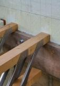
-
Any Architects on here?
Gus Potter replied to Mulberry View's topic in General Self Build & DIY Discussion
I got timed out. don't panic about the joists as by the looks of things it can be easily fixed if need be. But you need to get it checked. -
Any Architects on here?
Gus Potter replied to Mulberry View's topic in General Self Build & DIY Discussion
Sorry to say but I think you need to get your metal web joists supports checked not least. I had a quick scant at the photo at the start of your post and it is flagging stuff up at my end as an SE. The ledger piece that has the bolts into .. ICF, I have concerns about that. The method of supporting the metal web joists.. I suspect someone has had a "butcher" at them. I don't say this lightly so please take my observations on board and do something about it. I think you need to get an SE in here as I suspect that your builder may have been "improvising". Next @ETC has been chipping in.. his knowledge of construction details and even more importantly his knowledge of practical construction details seems to me to be exemplary.. my opinion is.. ignore his advice at you peril and have a look at his sugestions seriously. Also appreciate (I do) what ETC is sketching out. It a great demonstration of skill and practical experience, takes many years to perfect and demonstrates how you communicate an idea quickly and effectively. -
Fire protection of steels and this example?
Gus Potter replied to Alan Ambrose's topic in Building Regulations
Thank you for meeting me half way on this, much appreciated. -
Fire protection of steels and this example?
Gus Potter replied to Alan Ambrose's topic in Building Regulations
Ok to go back to the OP. I'll try and expand. Yes I should have clarified... but it should be clear even to you @DevilDamo that this is a bit of an unusual design and can could give ordinary folk on BH working off a budget a false impression. If you know about the regulations then we can cut to the chase? There are a number of cases how this can work. I'm going to keep this basic and generalise. If you want to discuss this more @DevilDamo then I will be happy to engage with you and have a techincal discussion. I would like it if you did engage as it would be healthy / a bit of a learning curve for BH members and for myself as I could get your take on the regs and SE / structural theory that lies behind all of that. Cases are: 1/ If it only carries a roof load.. then we can let the roof collapse provided if does not pull down the other parts of the structure that require a higher level of fire protection. 2/ There are cases when you actually don't need to fire protect beams at all to get your 30 minutes. In fact it is often beneficial to let the light weight part of the structure to burn away quickly leaving the main and heavy parts of the building intact. We take advantage of this approach when designing industrial buildings. What the OP has posted tends to apply in domestic applications.. UC sections can be used that have a low heated perimeter over area ratio thus you can have beams as maybe shown in the OP's post, I suspect they have dropped a bollock on this! I thought I had cut to the chase when Alan pointed out that there was load from above.. and thus we were not talking about a roof load only in terms of the building regs. @DevilDamoAnyway no harm done. But if you want to have a more of a blether about this then please be a devils advocate. At the end of the day I'm happy to share what I know and in doing so I'll probably learn a bit more from you and folk on BH can do so too. -
Truly DIY SIP construction…
Gus Potter replied to G and J's topic in Structural Insulated Panels (SIPs)
Maybe @Gus Potter Thank you for referencing me. I can chip in but my take on it and the potential solution is long as there are so many aspects to balance... it's late here so maybe for another day. The bit that is hard to do is not actually the cladding spec but how you fire protect the cavity but still allow for ventilation of the cavity. -
Fire protection of steels and this example?
Gus Potter replied to Alan Ambrose's topic in Building Regulations
The starting point here is to actually understand how the structure works. Only then can you come to an informed view. Every design if different. Now it gets technical as while it may not be carrying any vertical load it may be contributing to the stability of another element that requires a higher level of fire protection. Yes this is a slightly different part of the regs.. fire spread. Clearly what @Alan Ambrose has posted is a habitable space.. but not an apartment i.e a bedroom. Agree. Yes some of the stuff you see is complete bollocks and not compliant. My summary for folk on BH.. Use your common sense if starting out on the self building journey. If you want to refine you BC and SE design then great.. we call that value Engineering. But for fire.. be safe folks as there is often no second chance. I'm an SE / Designer and we often design for folk and builders doing daft things, we call this robustness and alternative load paths. This means that if sometihng fails you will see the building protesting.. cracking and groaning so you will get yourself and your family out in time. That is why in the UK we don't read about lots of folk getting hurt due to structural failures. But fire.. look at Grenfell and if you read the local papers you'll see that lots more folk die just in their "wee houses".. many more than Grenfell every year. My advice.. don't cut corners on fire design and safety. For a bit of insight. The fire regs are intended to meet these basic but not all criteria. 1/ They are intended to allow folk to escape from a building. 2/ They are intended not to put the fire fighter's lives at risk.and their families that they support financially. 3/ They are intended to not set light to surrounding buildings and this part of the regs dates back to the fire of London. 4/ They are not intended to allow you to save money and put other folk at risk. This means that if you cock up you may be asked to prove that you were not at fault.. you may have to fight a publically funded body not least to prove you were not at fault ..and could lose your shirt.. everything. My advice folks. If in any doubt play safe and don't cut corners on fire safety.. as if your house does go on fire and if you have taken the piss out the regs (have a mercenary streak) your insurer may not also pay out. There is a bit in the building regs in Scotland that says even if you get regs approval the liability lies with the designer. In summary there is a lot of good comments on BH about this.. but every project is different so please do your research. Good research can save you a lot of money and you can still be safe.. but it takes time and effort. There are no short cuts. -
Balcony leading to flat roof....does it need fall protection?
Gus Potter replied to Thorfun's topic in Flat Roofs
@GeorgeI am signed up to CROSS and an SCROSS so get all the notifications.. surely you don't think I'm not keeping up? No.. George.. I'm not going to tell you any more about your request to "ooh tell us more" but I can tell you this.. you are barking up the wrong tree.. I use my own name on BH.. would you care to expand on your statement and clarify? Some of the software you use may.. I may have had a hand in the engineering development.. I used to spend loads of time writing pops up notes for general SE's (maybe like you) saying.. hey unless you really know your stuff then don't change the default values. I have worked for well known SE Consultancies in the past and know how they can drop the ball. I can give you plenty examples of SE's who have failed and sometimes dangerously. I'm not going to do that in a Public forum. Let's leave it George and stick to having fun sharing what we know on BH and ecouraging young folk. -
Fabric and ventilation heat loss calculator
Gus Potter replied to Jeremy Harris's topic in Heat Insulation
Hiya all. I totally get your enthusiasm. But you are all spending a lot of time an effort juggling numbers, could be the JH spread sheet could be some nice high end software.. I too have some fancy software in my office but recognise that it's just a tool to give you a heads up. Some folk on BH actually think this will happpen in real life for no extra cost and you will be able to russle up a builder who will play the game.. you are living cloud cuckoo land. The reality is that you need to be able to get a local builder to execute your output and get material off the shelf.. Honestly as a self builder if you get so anal at this stage you have little chance of making your self build a success. I have self built my self and also built houses for othe self builders.. My advice is to use your calculations as a concept model and then adapt to what can be built at a reasonable cost to your specification. A good 50% of the above looks good on paper but is complete bollock in real life. If anyone has a problem with this then you can find my mobile number on my web site or just give me a call on 0771 308 1597.- 204 replies
-
- 1
-

-
- heat loss
- ventilation
- (and 4 more)
-
Balcony leading to flat roof....does it need fall protection?
Gus Potter replied to Thorfun's topic in Flat Roofs
Thank you for the kind words. I'm an SE and an Architectural deisgner as the day job. @PNAmble that is the kind of SE you need on a self build. SE's know a lot of stuff about other stuff and some of us will chip in to make sure you get looked after. Caution: Not all SE's are like this.. some.. I would never have anywhere near my projects.. I sometimes work as an SE on behalf of Contractors. I have a job on my books and the response from the main SE is bordering on me reporting him to the IStructE for negligance... but the Client will probably do this first. .. not all SE's are angels, some have an attitude problem. -
Balcony leading to flat roof....does it need fall protection?
Gus Potter replied to Thorfun's topic in Flat Roofs
That is me appealing to the refined..hey you can just go out with a cup of tea and hopefully have some pants on so as not to offend. Yes it is. For all on BH you may wonder if I'm having a laugh saying I would estimate an SE design fee of £1200.00 maybe plus vat. The actual SE work maybe only accounts for 50- 60% of the above fee. I know from experience that I could spend at least a day, maybe two trying to elicit the information and drawings from a Client / Builder so I can design the fixings and get the appearance / buildability right. If you want to get the best out of an SE give them the best info you have.. the more you make them guess the more expensive it becomes. -
Balcony leading to flat roof....does it need fall protection?
Gus Potter replied to Thorfun's topic in Flat Roofs
Hiya. Been busy with the day job but saw this post. Here are my thoughts.. It's got to start with the Architectural appearance.. I think when you look out the doors you need to see something slender on elevation. In other words you don't want to be seeing a heavy top hand rail on elevation or heavy ballusters. I thought.. try horizontal tension wires for the ballusters.. but they are climbable for kids.. rule that for now.. but look on the internet how pubs etc do it where they have a heavy handrail and cantilever it in to make it difficult to climb. Structurally I would look at taking some pretty slender corner posts up from the side walls (to the left and right of the doors at the green roof end) say 50 x 50 mm box section as it allows you more scope for fixing them through the cladding at the bottom. I would then form a standard welded guard rail / balusters with a bottom runner, maybe 20mm box section as ballusters and a top rail of your choice. This will be pretty stiff and will carry lots of load along it's plane. Normally we design these things to resist load perpendicular to the hand rail. We still do this but do some extra checks to get the hand rails to deliver more. This is the key as now you have something cup the side to the left and right of the doors that will stop the section parallel to the green roof form moving towards or away from the doors. To design the bit that separates the green roof from the balcony I would do the same as above but make the top rail out of.. (I'm guessing here as don't know the length) say 180 x10mm steel flat plate. This on elevation is a thin profile and would also give you a shelf you can sit you morning coffee and croissant on.. or whatever. To design this structurally it's quite complicated as you need to know about fixings and stiffness of a typical hand rail / balluster assembly. One secret is to avoid bending forces in and around the fixing location and convert all the forces to shear forces that better suit fixings. Proving it takes a bit of effort. Design cost say two and a half days to; draw it Architecturally and get the look right, do the calculations including fixing design, do a steel fab drawing and explain to others what they should be doing and answer any later questions that folk phone you up about and a bit of a hassle factor. Call that £1200 ex vat.. seems a lot but you pay for the expertise and knowledge. You can save the vat if you find an SE / designer that sticks below the vat threshold. Mind you you could easily blow much more than my budget design fee if you get it wrong.. also you'll have to live with it if it looks rough. Think of slender, breakfast or some G&T on a nice night sitting on that flat handrail plate.. no worries about puncturing the roof and it leaking in the winter! -
How likely is an auction item to work at all / well?
Gus Potter replied to saveasteading's topic in Barn Conversions
That's a good summary in terms of machinery. On the other hand if they are selling off timber or say insulation then it can be a good option. That said I used to buy lots of ducks and poultry from the Lanark auction mart.. no complaints.. -
EPCs are complete bo**ocks
Gus Potter replied to pulhamdown's topic in Energy Efficient & Sustainable Design Concepts
I feel for you.. but for £180.00 what did you expect? You are asking for professional advice. I've just paid for a washing machine engineer for a call out.. cost me 50.00 for an hour. I'm an SE that works for myself at home in my wee office. My rate varies from £35.00 per hour for say knocking out some TF panels to £275 - 300/ hour when I'm say doing high end stuff, fighting big claims against say the NHBC or fixing a big structural problem. In the round I have a mix of bread and butter jobs; small, medium and the high end stuff. My rates reflect my skills, experience, the risk I have to carry and the fact that I like to have a mix of work that I enjoy. But for £180.00 the assessor can't really spend that much time. I do some heat loss calcs and can tell you that in your case I would be looking for some thing in the region of £1000 - 1500 and then be able to justify that by the savings I would make you. Yes you are right the system is a lot of bollocks. I think you will find a more informed accessor but you'll need to pay accordingly as above. -
Good post. A few observations...may or may not help. I've got two particular contractors on my books that are good old school, do a quality job and reliable. One is handing over the business to their daughter the other to their son. Both can stick build TF's and prettty quickly. They are straight up and believe in a fair days work for a fair days pay. I've said to both the younger ones who are very competant.. keep the family ethos and I'll shove as much work as you need your way. Just don't take the piss.. stick to your family values and you will make a good living out of it, I've got plenty Clients that are prepared to pay for a fair days work etc. Their dad's are not scaping the barrel here financially by the way and have a long list of satisfied customers. I say to the youngsters.. yes you will need to compete for the work.. but when you lose a job I'll tell you where you went wrong. Also I'll do a bit of pre vetting on the Clients so it reduces the risk of you getting ripped off so that can make you even more competetive. To be blunt if I think a Clinet is a bit ropey then there is no way I'll expose the builders I trust without warning them. The rest of the chancers can swim with the sharks. That said I'm always happy to meet you Contractors that are up and coming and will often give them a chance as I was given when I started out as a young Contractor. It will take to time to find these types of reliable folk.. they are not the cheapest but in the round what you lose on the swings you get back on the roundabouts and often more.. like thousands! I've made other posts on stick frames.. explore the cost and savings, a couple of good joiners and a labourer can build you a cracking quality timber frame. That's how I used to do it and most of the Contractors I work with on extensions and self builds do it this way.. because it tends to be cheaper and that is how we all win the work.. I advocate organisation, simplicity and cost. In the old days we had a rough spec from the SE and Architect re the timber frame and just got on with it. Now I'm an SE I go out and inspect TF by some of the big suppliers and find so much wrong with them I wonder.. why are folk paying for this as self builders? In summary try and find a local firm that can knock up a TF and a designer that will do what I do.. You'll need to pay more for someone like me.. but the savings I can make far outweight the fee I charge. See what that cost is for the bare frame knocked up on site if you buy the materials.. not the nails and the gas for the nail gun etc and then compare what say MBC or Scot Frame are offering. Now you have a base price then you can see what you need to pay as an extra to get a more "packaged design" and make sure that any reduction in the lenght of build time is really worth the extra cost. Now when you weigh up the above you can maybe see how just a masonry cavity wall construction is appealing. It's got less to do with the materials and more to do with the hassle! But get it right and a TF is just as attractive.
-
Yes good link.. have had a quick look but they don't seem to cover water starvation and soil aeration. This is stuff that the arboriculturalist will cover in a speclist report.. which you may need to allow you to plan an economic design. If you get standard advice say NHBC etc then you could lose a lot of cash by being too conservative and even then you could damage the trees .. you will have wasted your money. For me I think that our heritage requires at times that we should keep established trees and we should be designing for this. A cracking tree can add value to your property so bear that in mind, don't always assume that the tree is a problem! Also, if you live in the South it can provide natural shading and light in the winter as is a deciduous tree.. if you are designing for a lot of glass then work with that when considering over heating in the summer? Now that could save you a lot of cash or get you out of a heat / gain thermal calculation problem when selecting your glazing!
-
Ok I've posted a bit about this before.. here is something similar. In the past I used to be a Contractor who site built a lot of Tfs. Now from time to time I design them as an SE and produce the panel drawings for others to knock up on site. Yes a site built kit can be top quality and also it gives you more flexibility if you want to make design changes. I can see that for folk on BH it's very hard to compare like with like when getting prices for TF's.. If you go to folk like MBC or say Scotframe in Scotland then you need to ask: 1/ What is the price for the bare timber frame walls.. in other words the studs, sheeting, lintels and floor joists. 2/ What is the price for the roof.. could be trusses or a loose cut roof. 3/ What is the erection price. Now you have itemised and costed the structural frame. Next you have the rest.. insulation.. vapour barriers, fire stopping,plasterboard, door frames etc .. every quote you get will throw a spanner in the works so you can't compare.. it's apples with oranges... this is deliberate as the real profit( the cream) for the TF folk lies in not in the simple TF but elsewhere. They also play about with the U values and chuck in assumptions.. like say windows with a U value of X of a floor insulation of Y and things like to be "specified by the SE". You may think that your self build is a big money job.. but the thing that really keeps the TF and roof truss companies ticking over is the volume market. Your self build is just a bit of PR and a chance to make a whacking profit. Also, as they are dealing with novices (mostly self builders) they factor in the hassle factor.. which us folk that do this as a day job don't give them. As a designer I say to my Clients.. we can go to a local joiner who can do your frame on site .. but for comparison you can go to the likes of MBC. Now when we get the prices back let's weigh all this up. The outcome on a self build is usually the folk I recommend get the job doing it as a site built frame / making it in a local barn. Of course it takes a bit longer to build a kit on site but you cut out a whole load of hassle, the design can be alterered easily.. avoids delay etc. Some Clients just want that big name.. it is all just done fast.. but once I start checking that all the interfaces are compatible.. often folk wish.. hey we should have gone the whole hog and site built the frame. Also the beauty of stick building it is that you don't need to pay an unsecured amount of money up front to TF folk. You buy the timber and pay a joiner to cut and nail it together. This can be handy when borrowing money.. My gut feeling is go for a site built TF by a local joiner and then package up the insualtion all the way through to the door sets / finishes etc in different ways and get prices from the mechants big and small. Most of the TF guys that stick build for me have served part of their time with the big builders anyway so it just a case of you ordering the material and letting them get on with it.. you cut out the middle man and from time to time you may want to make a cash donation for their kids charity run.
-
This is a big subject.. and I'm still learning about this as every day is a school day. About 15 -20 years ago I designed a training Gym for a well known London football club, they made the film Chariots of Fire there and when we were doing the work we found the long jump pit in the film.. made my year really.. what an exciting life you can live as an SE! .. it was a bit of nostalgia for me.. but very important to community. Anyway, as you can see in the film there are a lot of iconic trees, classic British refinement, elegance.. the council and local community were crawling all over us which I totally appreciated. The Client was less inclined to see things the way everyone else did. But I explained that as I'm primarily trained as a Civil Engineer (work for the community) then unless they engaged in a Civil manner there would be no new training Gym .. or they could sack me .. play hard ball.. but the council and community had them over a barrel. At the end of the day it was only a few weeks wages for one or two of their mid range players. Now we all talk about on BH about heave, soil shrinking and swelling but when near big trees we also need to think about water starvation of the root system. You don't want a big tree dying and falling on your house, also if under a TPO.. you will be liable if you cause it to die say a few years down the line because you starved it of water. On the Charoits of fire job I ran the roof water drainage back under the building.. but now I know what I know I may have starved the soil from worms and oxygen.. who knows? This is a great point from Jilly although she has not explicitly stated it. A tree needs structural roots to stop it falling over and roots that seek out water and nutrients. @Bluebaron yes you can build close to big trees but you'll need to spend time to understand how the tree is living as you could waste a lot of money just following general guidelines. In the round I think that we should be able to design to live with big old trees and as an SE / past builder/ into the country side this is something that intrests me. The big challenge is to convince others in an evidenced based way. That costs money which is not something that BH folk tend to have.. unless they put in time to learn! Folks there is no free lunch to self building.. it is hard work but very rewarding. When I finished my first self build I though.. add you own comments.. how good did you feel.. there are few folk that can do it! Post a bit more info and if you make an effort the folks like myself and others may chip in with a bit more detailed advice and a few pointers for free.
-
Hiya Nailbiter.. good choice of name for this situation. Good general advice from @George For all.. a few of my thoughts.. in no particular order.. If you are a self builder and newish to the game (say have self built less than a couple of houses that have basements) then it can be a challenge to get your head around each part of the design.. say basement and superstructure. A key feature here is to recognise that the bit that goes on top (the top bit) can have a big influence on how the basement (call this the bottom bit) is designed and how much cost that will attract if you don't recognise that the top bit and bottom bit don't interact. There are big savings to be made here. Self building tends to drive you down the road where you want to spend as little on say an SE / Architect etc as possible. You tend to split things up into different work packages.. it's the only way you can (with limited experience) to see conceptually how the finances will work. I've no problem with that, I've been a self builder in the past.. before I was an SE / Designer so can see both sides of the coin and I have myself isolated each work package... and thought.. I can steamline later I'll make a saving? I didn't but at least I still kept my shirt but I was younger then... too cocky! Every site is different. The design decisions you make are driven by many things. Say you are planning a self build with a full basement, have one on my books at the moment. My scope of works could be to act as an independant consultant who keeps a brief on how we are developing the early design. The other part of my brief is to design the bits that no one wants to. These tend to be the nasty bits and relate to the common practice of say TF suppliers / basement designers shedding off design liability to the Client. The main thing here is that we recognise that the actual concrete box basement could be braced by the floor at ground level.. here lies big savings! Also it there is a flotation risk ( as it's a full basement) and we are getting our heads round how we deal with that. The actual basement design and tanking system is driven by for example the ground conditions, water table and how we are going to get rid of the foul and surface water... you don't want you sewage running back towards your basement which is an inviting sump! We are spending time understanding this. The Client has spent targeted money on a site investigation.. they got me in early to comment on the scope of the SI so we have been able to discuss / plan together. Now we are getting close to being able to give the specialist basement designer a better quality of information which includes the Clients specific requirements which they have spent a lot of time putting on their wish list which needs to be met. All that saves money / time and hassle. To summarise.. my Client and I have not yet decided what type of water proofing we are going to adopt and in what combination. We know we will get something to work but can't do so until we have got lots of the drainage etc conceptually nutted out. @NailBiter I think you need to get a handle on the ground conditions, drainage before you can take a view on what Nadura et al are saying? In fairness to them they can only give general advice. If you want a bit of general advice post more info on your site. Do you have a full basement or a partial one for example where you can let any ground water out at the low end?
-
You've nailed it. Sometimes I make note on my drawings to say why I want a something to be the way it is. I made one today.. "we need this small timber strut to stop a big steel beam from twisting" it's £1.00 bit of wood but is essential to make the design economic. Now for the purist I'm deviating from the BS method of detailing. But after 40 years in this game I feel.. why not just put a few extra notes on the drawings to help folk that may not be aware of the pitfalls? In the last few years I've just started writing this stuff on my drawings in plain English rather than being a smart arse and making folk jump though hoops. Contractors, Architect's et al and have a hard enough job as it is. Why do I do this plain English thing.. short story. I had a dispute with the NHBC (not the first or last time) .. big claim several hundred thousand which I won on behalf of the Client. NHBC sent Professor Barry Hasseltine up to Scotland to investigate. Prof Hasseletine wrote a lot of the books that we as SE's use and also had a hand in the design codes we use. The Prof and I agreed and the claim was paid. His report astounded me.. a teenager could have understood what he had written.. his English was very basic but very elegant.. he told a captivating story... evidence based... but at the end he included his qualifications and experience just in case a dafty though his plain English indicated a lack comprehension of the problem.. wow! What a skill and craftmanship in report writing he demonstrated.. that is one of the main reasons I try and write the way I do on this forum... keep it simple and use plain English. Raft slabs, ground bearing slabs, how we insulate them and move more towards making the Passive slab affordable are the things of the future. I got into this about 15 years ago.. it's exciting and I'm still learning.. I've got a grasp of the SE design but still trying to find a way to make it affordable for common constuction. I've got a few local builders getting into it now so the wagon seems to be rolling. I can tell you when and where you need to reinforce slabs on EPS, but I've spent 15 years learning how to do this; firstly in a commercial environment, cold stores and in the very competetive cold formed steel industrial shed market (take this as 700 buildings a year all over the UK!) and much of this happened long before the self build folk caught onto it. Yes.. lots of SE's take fright when faced with this kind of thing.. but many Clients want to have their cake and eat it.. in terms of long term service and risk. SE's are an easy target as lots of folk know we carry high levels of PI insurance. The easy way to explain this.. we as SE's that carry the PI insurance (the important bit) need to make things safe so they won't fall down and kill folk. If things start to bend a bit and your windows, doors, roof, basement starts leaking after say ten years then so long as you the Client accept this (serviceability) risk then we can progress. A big changed happened with the adoption of the Eurocodes which let us "negotiate" the serviceability so long as it does not compromise safety. Clever eh? but for the less "open" type of designer. a way to win your design brief! But for the average self build on BH that needs lending it doesn't fly as you can't negotiate the serviceabilty. The SE needs to make the design compatible with the mortgage lender criteria. @saveasteadingThat is why you may be correct on over designed slabs etc but it just does not fly for the average member on BH.
-
Slab/Raft Foundation - Steel Reinforcement Question
Gus Potter replied to TonyE's topic in Foundations
And a Hi from me too! Hope this helps a bit although a bit long winded. I'll assume this is some kind of reinforced concrete raft rather than a basic ground bearing slab ... yes.. may be stating the obvious and that we are talking about a self build rather than say a tightly controlled and site managed design where you have professional staff on site most of the time. My starting point when designing anything like this is to look at what resources the Client has availabe to "manage" the construction and control the quality of the work. Do they want to use general builders and thus say be able to obtain more quotes or do they want to go for specialists for each work package and thus limit the spread. There is no free lunch here.. it's about getting the right balance that will work on your project for you and that takes a bit of work.. but get it right and you can save a lot of money. Ok say we have identified they way you are set up.. the time you have available and your budget. If I have this information I start by looking at how flat and level we can get the medium under the concrete slab and what that will cost in terms of labour and expertise on behalf of the Contractor. This could be type one with a bit of blinding or your insulation. Remember the sheets of insulation are not perfectly flat.. and can take a fair bit of weight to make them so! Don't believe me.. go and ask the insulation supplier how flat their insulation is... not the thickness variation! I'll often specify what is directly under the slab with a level tolerance of say +0.0mm to -15mm (half an inch in old money). What I don't want to have is a lot of really low spots.. the slab needs to shrink as it cures / dries out so massive thick bits of slab are not good as they lock the slab to the ground and promote cracking. @saveasteading et al have a more nuanced take on this slab shrinkage which we have discussed but stick to the basics for now. By setting a limit of +0.0mm I can then be sure that the slab is not going to be thinned out from below and compromise the cover to the reinforcement and what we call the effective depth. The effective depth is used when we design the slab for stength for example. But if you are a contractor any low spots .. needs extra concrete and that has to be factored into the cost. Next I look at what is going to go on top of the slab.. how flat ( low and high spots) and level (measured over set datums) do we need it to be? There are common industry standards for this.. I'll not post now as it's lengthy although have posted info on this in the past. Anyway we need to know the tolerances of the top of the slab. Say you get your slab laid an you have low spots.. now your cover could be 10mm? Once I know the top and bottom limits / tolerances I can get on with designing the slab itself so it will carry the loads require of it.. There tends to be some intial criteria here..for small DIY self build designs and I make some comment: 1/ Ok don't be clever at this stage.. there will be plenty time to get smart later.. fix problems that will arise during construction..when the rain is pouring down say and folk don't turn up.. go simple stupid for now. 2/ You want to be able to get everything off the shelf. Your A393 mesh is.. harder to get flying end mesh in small quantities. You can convert a mesh to a flying end on site by cutting it with a Sthil saw / angle grinder. For another day but plenty of folks on BH have done this and can tell you how to do it as do the builders I work with. 3/ It looks like your slab has some loading that causes a downwards and upwards bending force as you move along the slab.. hence the reinforcement in the top and bottom. Your SE has identified this and maybe made a judgement to go for a thicker slab and stuck to a standard off the shelf mesh. Ok some folk may disagree with the thicker looking slab.. but in the round I'm guessing it looks a good play if you take into account the buildability and top / bottom tolerances as above. 4/ There are load of folk on BH that say.. hey we didn't have to use this or that. There is a fundamental misunderstanding that can arise here. A true ground bearing slab is NOT a reinforced concrete slab but what you have looks like a reinforced concrete member.. just like you would see in a multi storey carpark. When we design reinforced concrete there is a bit in the design codes that require a minimum percentage of steel.. often this minimum percentage steel works for most of the raft type things. Summary.. It looks to me that this a slab that could be justified on cost based on a DIY job.. but ask ten folk like me and you'll get ten different answers! But here is the where I think you will struggle and find it very difficult to set out the mesh and get it compliant with the design. yIt may look great on the drawing but any bent rebar comes with a bending tolerance as does the mesh. I don't think your designer has taken this into account and the site circumstances. I feel your 30mm cover is too ambitious for this type of project.. you are making a rod for your own back and I would not design it this way for that reason. The U bars don't in real life come like this.. there are bend radius tolerances and length tolerances. You can find this on the rebar suppliers web sites and also in BS 8666, etc for those that want to check. In other words I think you cover is going to make this very hard for you and you will struggle to execute this. Recomendations: 1/ List how you are going to do this part of the work.. the sequencing and what the skills are of the Contractors you have in mind. This will help as if you can explain this to yourself then you can explain to others. 2/ Go back to your SE and ask if you can increase the cover. They may say yes but there may be some local areas of the slab where we need some extra lose rebar.. say under walls or columns. Fine.. Travis Perkins et al do 3.0m bars off the shelf and you can chuck them in where the stress in the concrete is higher.. but your SE may need to do a bit extra work. 3/ If your SE protests then ask.. hey I told you this was a self build.. you tell me how I can reasonable achieve a 30mm cover without breaking the bank! @TonyE hope this helps and all the best.. -
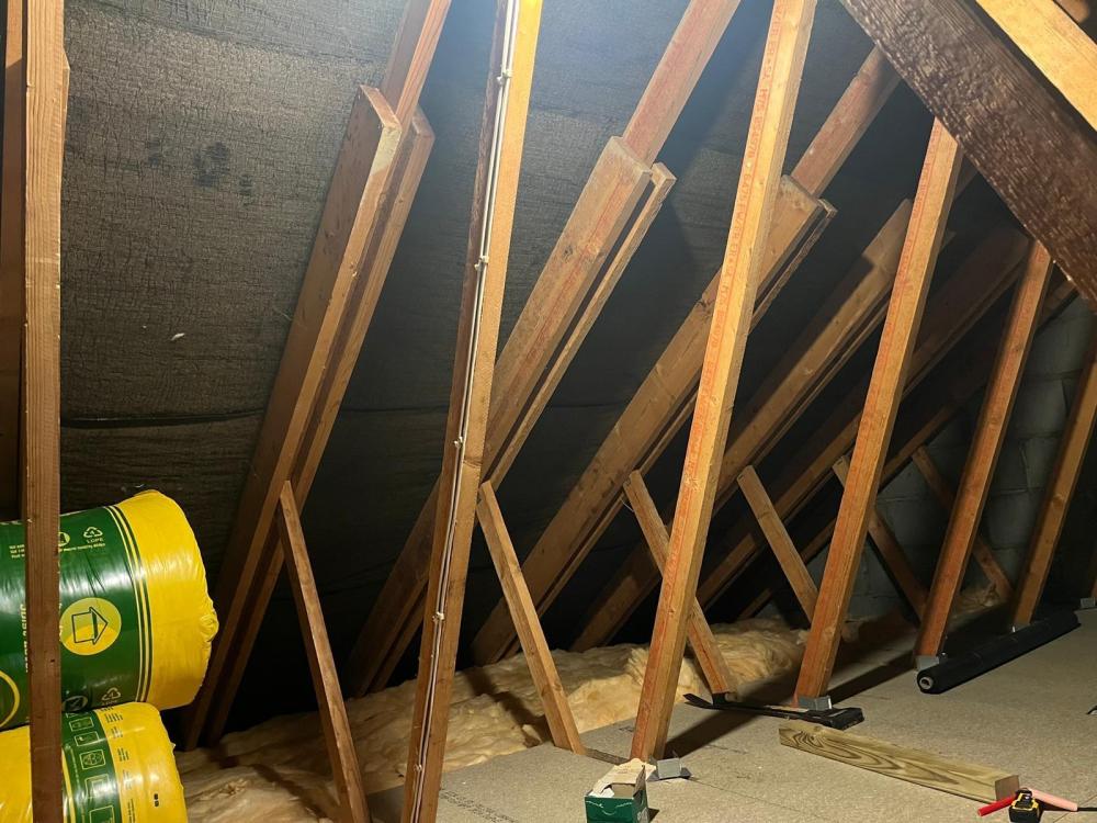
When we design prefabricated roof trusses we sometimes use a thing called a "superchord" which is basically a sistering thing which strengthens the rafter locally. If you look at the stamping on the timber main truss rafter in the photo copied below, the web, rafter and sistering.. all have similar markings in terms of print colour and text layout. What you see may be part of the original truss. The timber use for a trussed rafter in the UK is not that available "off the shelf".. usually a UK truss timber grade is TR26. Thus it's not a common timber that you would use to alter a roof. It may well be that what you see (sistering each side of the rafters) is part of the original truss and that could be assocaited with say an extended eaves or a series of point loads say from another roof framing into it as other have mentioned I would go back an look carefully at the timber stamping and the eaves detail etc before jumping to a conclusion that says the previous owners have been mucking about with it.