


Olf
-
Posts
315 -
Joined
-
Last visited
Everything posted by Olf
-
I've drawn the layout and calculated number of boards assuming that because they are tongue & groove (and boneded with foaming glue) it does not matter where they meet. However reading now advanced fitting guide it states: All short end joints should always fall on the centre of a secured joist including perimeter edges. Is that the case in practice? Of course in my refurb joist spacing appears to be random, if I was to follow that rule, instead of 3 boards per row (7m internal width, 3x2.4m boards should do it) I probably need another one for each row, if the previous 3 are chopped to match the joists. And is square edge sitting on the joist more rigid than suspended glued tongue & groove?
-
Do you have a proper design of the raft (by a structural engineer)? It's hard to do precise figures based on vague assumptions Can you not get lorryloads of hardcore? Why use binding concrete under concrete raft? Sounds a lot, especially for an average. That feeds 6-8 people, I'm not sure if there is enough room for them not to bump into one another. Saying that, this is surely the are where biggest savings can be achieved, search for many stories of those that had fun with diggers on their builds
-
Now I get it, somehow missed the fact that underscore is not an emphasis, but a link Regarding the venting, no I was lucky to not to have to research it, but feels like the obvious thing to do: - typically one uses stock vents above ground level (airbricks) - if levels are off, you use telescopic version of that - if a wall obstructed (eg by an extension), then run piped connection from existing airbricks to a new wall - if that cannot be done (and it seems to be your case) the only way is up... Whatever you'll do, it looks like to be of non-standard approach, so run it with your BC to make sure they're happy.
-
Is there any specific problem with suspended timber floor, that prompts you to lift up a slab? If venting under the timber is an issue and you have all this challenges at the back (slab, ground level) have you though about venting at roof level ? That will likely involve boxing of pipes, but will still be much quicker and cheaper, with better effect (due to 'chinmney' action).
-
You remove (from heat loss at least, but to large extent physically) one wall of W width and replace it with a new one of W width (back wall), 2 side walls of L length and floor and roof of WxL area. So assuming your extension is a cube (the optimal shape from efficiency perspective), the losses through each of your new surfaces must be 1/5 of the existing one - and that's the best case. You assume Victorian = Very bad, but do check the numbers Yes, there are plenty of online U calculators to get idea of your current wall performance, search here of 'Jeremy Harris spreadsheet' to get new figures I did something similar and ended up with a situation, where rads (existing building) typically call for heat for longer than the new UFH. So the UFH became a new 'radiator', than 'opens' (via pump rather than TRV) and shares circuit with the rest. So I did rely on the existing single stat in the old house, with UFH wiring centre completely independent. I replaced it now with a stat linked to the wiring centre, occasional cases where UFH calls for heat mean that rads heat as well, but the net result is only change in timing, rather than extra unnecessary output (and rads have TRVs, so would close if too hot). How you want to link and program your heat emiters is down to your preference of heating: stable temperature all day long on one end vs some rooms warmer and some colder over specific periods. It is specified on the valve and adjusted by the user to the required temperature. Typically they come in 35-70 flavour, in low heat buildings those blending down to 25 (or lower) are recommended though. 'Required' is combination of many factors: floor surface (some have limits), rate of temperature rise, risk of heat source short cycling etc.
-
I think there really are only 2 thresholds: building regs and passive house. BR condition to meet specific value may result in need to have more than 'standard' (like in JohnMo's case), and for PH to have whatever makes the building 'net zero'. There might be 3rd condition, cases with UFH and specific floor finishes, where losses downwards are expected to be large if not tackled by extra insutation. But in principle, based on maths explained here, it makes little sense to voluntarily improve above BR requirements, as payback time is too long to justify. Though this reduces quickly: I checked recently and the same board at the same supplier costs the same as when I bough last year, but energy price is now 3x more - and so the payback time reduced 3x. But that calculation is based on insulation material price only, you rightly mentioned that it may be necessary to dig space for it as well, handling thicker material has also extra associated cost.
-
Spiral or serpentine UFH layout - which is better?
Olf replied to low_and_there's topic in Underfloor Heating
Define 'better' and then you have the answer Spiral: more uniform floor temperature, harder to plan laying but easier to execute (no 180deg bends except the very centre), and because of that lower flow resisitance Serpentine: gradient of floor temperature as the water gets colder, not much thinking of the layout but fight with the ends to not to kink the pipe and stop it from raising. The gradient is not necessarily bad thing, if the house requires low heat output (so what floor can give is not a limiting factor), having cold end of a loop running along the walls further reduces heat losses. And there is a 'better' of overlay boards: serpentine have constant spacing of linear channels, so you can have them ready made. Spiral requires constatly changing radius, so it would have to be custom Generally MVHR moves less heat than UFH can produce, so don't count on that -
If you can have a slab, then go for it: no bounce and cheaper to make. And if you have a choice of screed on insulation on slab vs structural slab, always take the latter. Why do you want higher floor thermal mass in an extension? Floor volume is relatively smaller to the overal volume (driven by at least 3 walls) than in case of the main building, so any difference here will be proportionally smaller.
-
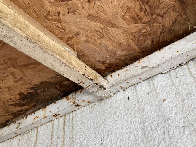
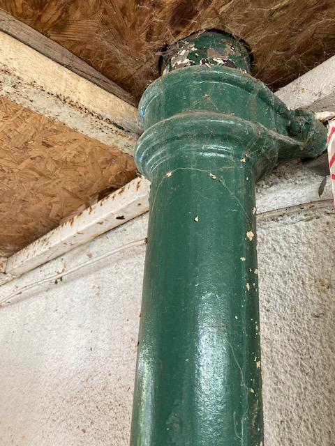
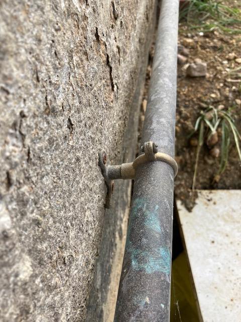
Planning for installation of EWI, but have existing amenities in place: 1. Carport roof structure - I'd be ok to leave it attached to the wall, my thinking is that if to remove it and then rebuild, extra pillars to support it off the ground would be needed - or am I wrong and there is still a way to hang it on/through EPS? Assuming it stays bolted to the wall, the crossmembers are cold bridging - is there any high shear low conductivity material so I cut the section the box profile and slot in (and/or around) to create a thermal break? 2. Drain pipe - I'd love to hide it and not see anymore, any issues with that? It is vented to atmosphere, is additional 90 deg elbow at the top enough to breathe outside of EWI? 3. Gas pipe - I suspect it needs some freedom for thermal expansion, but otherwise is there anything against being hidden in a channel made in EPS? I realise channeling/cutting around these obstacles adds complexity to the installation and sightly reduces performance of the insulation, but still may be more beneficial (less hassle than moving the obstacles) and provide visual benefits of hiding the pipes.
-
I'm not sure if Thermoblock would be ok for mounting TF to, but moot point if out of budget. Second best option to mitigate bridging would be perimeter insulation using phenolic.
-
It's outside of insulation envelope, having the best insulator thee will do nothing (or close to nothing). Instead I'd think hard how to replace the kickerblock to avoid cold bridge there (and still be able to mount TF well)
-
SF60 has 120mm thickness, so that would be equivalent to lambda (or K) of 0.29 - pretty realistic. What is not realistic is that you pay over £21/m2 for that performance (https://www.wickes.co.uk/SuperFOIL-SF60FR-Multifoil-Insulation-Roll-1500mm-x-8m/p/237123) so roughly 6 times more than wool https://www.wickes.co.uk/Knauf-Insulation-Space-Standard-Top-Up-170mm-Loft-Roll---6-47m²/p/109450 Even after adding reflective VLC (like https://passivehousesystems.co.uk/product/phs-hi-thermia-reflective-membrane/) there is a lot of change left. There are caveats to that performance though: - the quoted R takes into account surfaces and continuity of the material, the core itself is probably on par with wool at between 0.3 and 0.4 - it is reduced to 0 where attached to rafters, so with 600mm centres and 75mm wide rafter effective R drops close to 3, and probably more as it takes some distance to expand from 0 to 120, and compression reduces performance Big worry is also that their BBA certificate has been suspended https://www.bbacerts.co.uk/2022/01/07/december-2021-new-withdrawn-certificates/ Be careful, as your statement is as misleading as salesman talk: R value is not meaningless without thickness. Thermal resistance of a surface is non-zero, yet its thickness is. And even for those cases that indeed can be calculated by the equation above, R can still be better, if k changes with thickness - which frankly is the case for most of the commonly used materials: PIR and phenolic lambda improve with sheet thickness, wool performance drops.
-
Parasitic upstairs heating is possible, but be careful here: - you seem to have large floor area and relatively small stairs opening for convection - assuming MVHR is present it will help transferring some heat - if upstairs floor is well insulated acoustically (as it should), it will block conduction - depending on what is above (you mention attic, so should be ok) you may still lose more through the roof than is delivered from the ground floor
-
Are you planning to use any government scheme for ASHP installation, where you are at mercy of the supplier with them working hard to maximise their benefit? If not, are you planning to keep the gas or rip it out? If the former, then you have a backup and can optimise the ASHP size even better.
-
This looks like lazy approach of the designer, just letting loopcad spit something out in no time I would: - put at least kitchen manifold (if not both) in boot room - boot room and entrance heated by runs to the other rooms only, likely still requires insulating most of the pipes (especially hot legs) - too many loops: study 1 should be enough, kitchen & living 2 - fewer loops (I ended up with 8)= shorter manifold, you may be able to reduce to 1 manifold only with simplification of supply plumbing and controls - consider spiral loops in most of the rooms: more even heat delivery, easier to lay, lower flow resistance. - as mentioned earlier no pipes under any fixed units and anywhere near the fridge in the kitchen, nor in the places in the WC (as explained earlier). The loss of heat delivery there will be compensated by towel rail. Tbh I'd run one loop for WC (hot leg incoming here) and utility, passing under the wall is not a big deal: just insulate the pipes
-
CLS have standard (albeit Canadian) dimensions, if you fit door frame that makes a bit easier to find a matching kit.
- 1 reply
-
- 1
-

-
UFH pipes in concrete slab, on insulation or tied to mesh
Olf replied to Chanmenie's topic in Foundations
It may be, but you need a tool and extra spend on clips. Also it would have to be planned carefully to not to collide with the chairs for rebar, so I think tying to the mesh is the way to go. Not sure about your shoe size, but 15cm between the bars is enough to put a foot on 2 adjacent, you can easily go forwards and sideways, bigger issue is reversing and not stepping on the pipes Irrelevant, flow temperatures are the same. Saying that, my thinking is that rebar would help to transfer heat from the pipes attached to it initially. Mind that with pipes at insulation level, the same will happen once the heat reaches the mesh above, and considering UFH heating is all about slow and steady, it should not matter in the end. Also my thinking is that UFH pipes at mesh level should result with slightly lower losses: at 35°C flow temperature I get 25°C surface temperature. With pipes roughly in the middle of the slab I'd expect bottom of it (where it touches insulation) will also be at ~ 25°C. Pipes attached directly to the insulation means something close to the flow temperature is reached there, and so higher heat flow happens downwards. You need another layer of membrane (thinnest DPM you can find) on Celotex to stop reaction of aluminium facing with concrete, also prevent any leaks between the panels (just in case, even if foamed). As mentioned earlier, apart from compression lagging around, do install perimeter insulation to prevent bridging to the walls. Put it between DPM and the 2nd membrane, otherwise it will float away. I've seen opinions that EPS is 'soft' enough to act as both, though PIR will have better properties. Also all the services going through the slab will benefit from being wrapped in lagging And last but not least make expansion joint in any doorways, otherwise they'll form naturally. Through those places make sure UFH pipes are bent (even forcing S shape) and covered in pipe insulation, so they can move a bit within once the slab is settling. -
Beamshield requires void underneath, as it is beam&block system, just EPS block. The greatest drawback is need for protection from damage during further stages of the build. From other practical issues it may be the supply: finding local casting company that collaborates with them (though there are similar alternative systems), volume required (whole house is more likely to succeed, my extension failed to fill an artic) and competition from volume builders if present around (one of the companies I talked with at some stage pulled out, as their whole output was sucked by major developer). But in principle yes, it's a no brainer. Though so is single skin externally insulated wall as used throughout Europe, yet cavity rules
-
Yeah, I figured that! Hence I'm thinking about employing shmbo to do the levelling, and from that perspective a roller on a stick is more manageable.
-
Is it worth investing in spiked roller, or will any agitation (trowel?) be sufficient to keep the self levelling goo awake enough so it settles dead flat? The biggest room is 30sqm for the sake of argument, it needs to compensate for up to (down to?) 10mm depressions.
-
Is my house suitable?
Olf replied to jayc89's topic in Mechanical Ventilation with Heat Recovery (MVHR)
I say yes, as that's what I did before: I ran MVHR ducts only where I could. Building airtightness was poor, but it nevertheless brought noticeable difference to air quality inside. The reason is it provides/extract air where you want and how much you want, natural draughts are temperature and pressure dependant. You loose a lot of heat recovery component, so go with as cheap unit as it gets, as efficiency (long term economy) will be of less importance vs upfront purchase cost. -
That will be it, I had the same issue. Do triple check the settings for scaling when exporting - when printed from CAD itself it knows what to do, but PDF viewer (my LA uses Foxit, you can download it for free to test) will scale to the tags experted
-
Surface/rainwater drainage design for extension
Olf replied to Alex3012's topic in House Extensions & Conservatories
Nope: water companies 'adopted' what got defined as public (shared) drains in 2011. These drains can run in the gardens and Wessex Water have no idea where - the map only shows what they build, so likely only pre-2011 along the roads. -
Engineered oak over UFH glue or float an which underlay?
Olf replied to Barryscotland's topic in Wood & Laminate Flooring
Any recommendation for the glue to be used, especially with UFH in mind (thermal properties)? -
Surface/rainwater drainage design for extension
Olf replied to Alex3012's topic in House Extensions & Conservatories
Do not assume that currently there is a soakaway serving the house. Dig up and follow the rwp and see where it gets to. Mine led to a storm sewer running shallow right under the planned extension, but I learnt that only when digging for foundation trenches exposed it... You need to keep specific distances from the boundaries to build a soakaway to start with (2.5m from boundaries, 5m from the nearest building as far as I remember), so you may end up with that already being a limitation. If still lucky, your percolation test may fail. If there is a rainwater sewer around (must be) you'll end up negotiating connection with water supply company, otherwise some clever water attenuation solutions would have to be the way to go.
