
Leaderboard


Popular Content
Showing content with the highest reputation on 01/22/18 in all areas
-
On the last one I fitted 25mm celotex with 50mm screws and some penny washers. Just sink them so the washer pulls in and bingo. Use the foam to fill the gaps around the perimeter, and foil tape the butt joints. 8 or 9 fixing per sheet is ample, but remember NOT to leave any screws proud or they'll hold the OSB proud.2 points
-
Just a heads up to anybody planning on doing some site clearance, or tree/shrub removal make sure you have put the wheels in motion to get it done before bird nesting starts, usually March the 1st if you are going to be using any mechanical means of removal. Ive just had the lads in with a big flail to smash all the hedges back, even though we are still in discussions with the planners, the last thing you want is to get consent and not be able to proceed because of a bit of hedge in your way.1 point
-
Alternatively offer to pay your builder outstanding invoices from his suppliers with your credit card.1 point
-
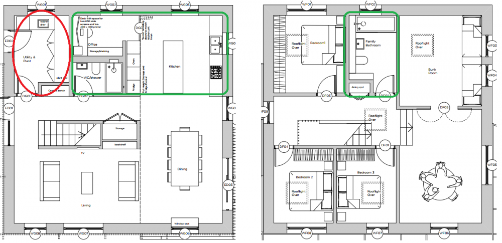
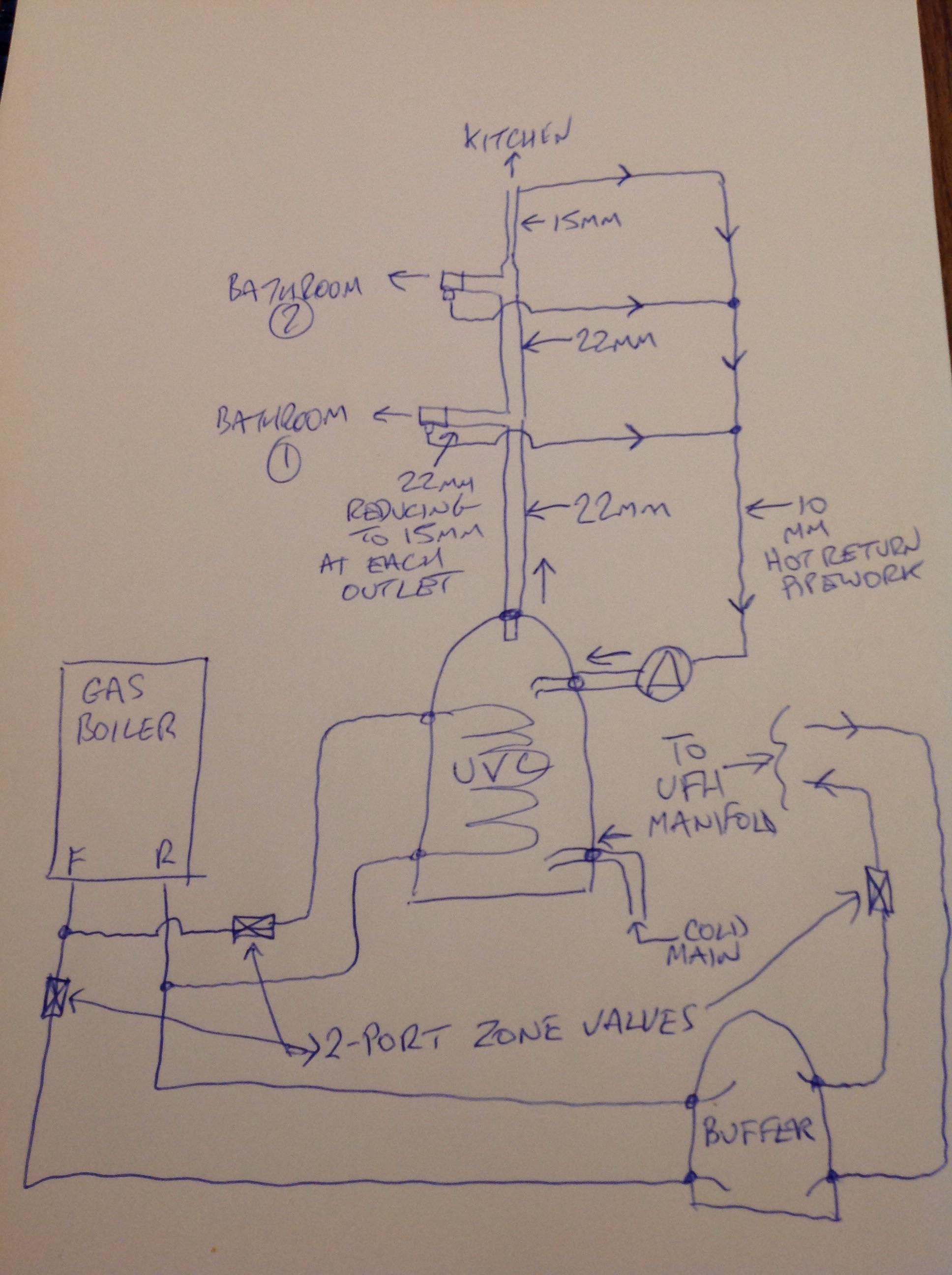
Awesome feedback, thanks all! Thank goodness it's early days and I've got time to spend on this learning curve... I have decided with the good wisdom of you all not to poison the family with the UFH using wholesome water! The SO will be proud! Thanks for pointing that out, I've fixed the original post It's just Watts, so that'd 50.4 kWh/day, or ~1512 kWh/month. That's worst case however. On average it'd be about a 3rd lower, at about 32 kWh/day, or 950 kWh/month. Agreed, I got ahead of myself. It was useful to think about the pluming but it is clear I need to settle on the principle systems None as of yet. We've got nothing but the land so far, foundation is going in march, so it's a blank slate thankfully. No limitations at present! Good point. The system wont be centrally mounted (utility room in red), however the majority of the runs will be under 4m in the areas I've highlighted green. Only exception will be the Kitchen sink which will be about a 10m run. LHS Ground, RHS First Floor: Great diagram @Nickfromwales, I believe I get what a hot return is now. Given that I'm still getting my head around much of the terminology here, I'll summarize for myself: a hot return is basically a loop with a pump that constantly recycles the hot water feed. This eliminates the water from getting cold prior to the outlets, thus reducing the amount of time waiting for the water to get warm when you turn on the tap? Ultimately it looks like the gas UVC is here to stay, ASHP is out, and PV is a maybe (the capital costs may push it back to some years after the build is done!). The Sunamp heat battery comes up a lot on the forum, so I'll have to do a bit more reading into it - I take it they have to be combined with PV to enable you to forfeit the boiler? I know Andy from Sunamp will be at the NSBRC convention this weekend, so I'll update my design following everyone's input and shall see what he thinks.
 1 point
 -
How about spray adhesive? Surprisingly sticky! https://www.screwfix.com/p/no-nonsense-contact-adhesive-natural-500ml/32657 Failing that a "grab" adhesive. Whatever's cheapest I reckon.1 point
-
@readiescards, you can run that stuff between Dover and Calais without a single worry. Perfect for your wet gate duct imo.1 point
-
Spec APPLICATIONS OVERVIEW Our H07RN-F is a heavy-duty rubber flexible trailing cable for power supply with a voltage rating of 450/750V designed to provide high flexibility and to withstand chemical, mechanical and thermal stresses. It is suitable for applications such as handling equipment, mobile power supplies, worksites, stage and audio visual equipment, port areas and dams. As part of Eland Cables' portfolio of rubber flexible cables, the tough rubber sheath also makes this cable suitable for use in drainage and water treatment, cold or refrigerated environments, and severe industrial environments. And yes, he is paranoid1 point
-
It can give you quite a headache, this plumbing lark...... Excellent real life figures there. Theres also still the Heat battery ( like a Sunamp ) to consider. No boiler, no ASHP, and almost zero maintenance / moving parts etc but also with near zero latent losses too. Im currently specifying one with 18kw/hr of Sunamp heat battery, and have steered away from the originally assumed ASHP altogether. PV will feature but with enough capacity to be recharged every evening on E7 /E10, its a VERY slick installation with masses of DHW available that could easily be used without PV. Grid electricity will fortify any short fall / provide boost for higher occupancy ( guests ). I'm awaiting @AndyT to update on things 'up and coming' before going into more depth on that setup.1 point
-
I would say not so clear-cut and if I had the choice I would stick with gas. Here is a posting I made a while ago illustrating the options, though I did not factor in RHI payments. The cost of installation is likely to be higher for a certified install ("RHI premium"). Do note that standard ASHP is only really good for water at 50 or 55C - to raise it beyond that you either have a 2-stage ASHP or direct electrical heating. Gas offers higher temperatures so you could get away with a smaller DHW cylinder. I also came across this article from a few years ago. Not sure how accurate it is, but I lean towards the same conclusion. http://www.narecde.co.uk/air-source-heat-pumps-vs-gas-boilers/ A lot will depend on your overall system efficiency. Our ASHP system is giving a whole system coefficient of >4 in a mixed DHW + space heating scenario, even in Dec and so far also Jan. This is for whole system energy so includes pumps, valves etc. Not the same as a COP. So factor in PV and I think this is a great combination financially. But mains gas without PV would save you £7k (ish) in capital costs and seems a more compelling case.1 point
-
Having moved into our dream in Oct 2016 I am now turning my mind to regular maintenance needs - what is essential / planned and what can be left to fix when it breaks? My initial thoughts... ASHP comes with a 5 year warranty, and there is a list of checks in the manual e.g. electrical, pressure, valves etc. Would I benefit from an annual inspection? I cleaned out the in-line strainer after 1 year, it had a layer of very fine grey powder in it. Filled with Sentinel X100 soon after commissioning. UVC tundish are visible and I can check for drips periodically - anything else? UFH? Just been keeping an eye on water pressure, I spotted a pressure drop in Dec and found a small leak, fixed. Water softener has a Clack valve, which can display error codes. inclined to run it until I get an error? MVHR I have been checking / replacing air filters and washed out the heat exchanger last summer. Solar PV and inverter. Apart from checking for mould on panels, anything else? Structure - MBC timberframe and ICF basement? Boiling tap, check tundish and change filter. External finishes are designed to be as low maintenance as possible, so don't think anything is required here other than keeping an eye out for damage. Render on board, brick slips, Lindab steel guttering and downpipes, Al clad windows, clay roof tiles, Cembonit through-coloured soffits and fascias, untreated Canadian western red cedar, steel garage doors, block paving. We also have some raised beds made from timber (i.e. modern railway sleepers). Inclined to leave them until they fall apart?1 point
-
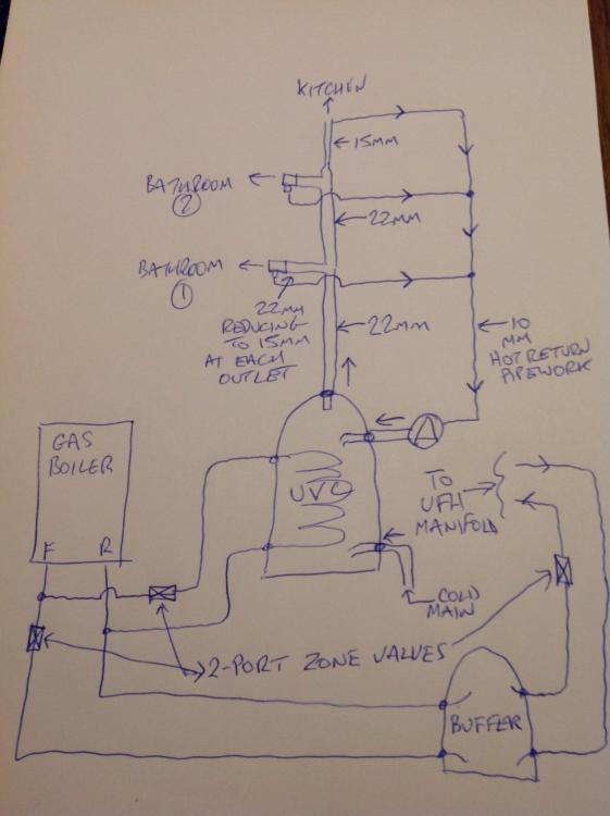
@Visti Just as a reality check, that having a flue penetration in the wall of the house is of very little consequence. You can still make it airtight and you can fill the sleeve ( duct ) with intumescent expanding foam for a bit of insulation. Yes it'll be a slight cold bridge, but the latent loss off the boiler will offset that by a huge factor. ASHP or gas boiler ? GAS BOILER! Smaller tanks, less installation complexity, no antifreeze, common and simpler controls ( so setting up and operating it is childs play ) and still a reasonable unit running cost per kWh. What boiler do you have now? Do you need to replace / upsize ? The 'beauty' of the manifold setup only comes into play if it's centrally mounted and sees short-ish runs from the manifold to the hot outlets. ( the cold is not an issue ). If the plant room is off side and leaves you long runs to two or more outlets then it may be a candidate for a standard series plumbed configuration, and the introduction of a hot return circuit and pump. I agree, if you have mixer taps then the secondary TMV is a luxury item that can be dropped from the design, but as they're so bloody cheap I choose to install where possible as a comfort measure as much as for safety. If there are a house full of little ones who will grow up there, it's a no brainer. Fwiw, the image where you see two TMVs is one where a TS has been fitted, so comes factory supplied with a TMV to cap the output temp ( usually 50-55oC ) as a measure for anti scald and to mitigate any excess energy wastage. A TS will typically store water ( primary heating grade water ) at a much higher temperature conmpared to an UVC so these are two different beasts with two entirely different uses and installation requirements. An UVC is full of drinking quality potable water, stored ready to be drawn off at the tap, and a TS is full of non potable ( primary heating grade ) water which has an instantaneous DHW coil sat in the water which instantly converts incoming cold water to hot DHW, so basically a giant combi that uses heated water instead of gas as the energy medium. An UVC does not require the primary TMV, in fact it requires no TMV at all. If you decide on the hot return and series plumbing you definitely want the UVC, sized between 250L - 300L ( 300L better if you ever decide on solar pv ( NOT solar thermal )) and to order the UVC with a hot return tapping to accept the pumped DHW return. As I know you'll be wondering what the hot return is all about : Lol. Another way of doing things
 1 point
 -
some slight developments in that I went out for quotes for the roof structure just incase they were reasonable. its roughly 200m2 30k including Spanish slate, or 23k if I provide my own... that 30k would cover sarking, membrane, slating/ridge and leadwork.. but not include the two small sarnafil catslides. 30k!... wow. anyway I've cracked on with a slight dislike for roofing companies I've purchased my own slates, 16x8 (400 x 200) welsh purple slates, reclaimed from the local (ish) prison that was knocked down. fantastic condition, straight and flat. 90p a slate. ( In need circa 6000) they are being delivered on wednesday 30k... honestly... I'm in the wrong job.1 point
-
Insulated pipe work for a Monobloc ashp can leave the thermal envelope through the floor slab. If the alternative is a flue from a gas boiler then I reckon in terms of heat loss the ashp would be preferred. With regard to noise, have you looked at a split type ASHP? Where the external condenser and internal compressor are separated. This gives you the option of placing the condenser around 30m away. I think you need to decide how you are going to power your systems before getting into the detail of design.1 point
-
That limit only applies when you are out and about.1 point
-
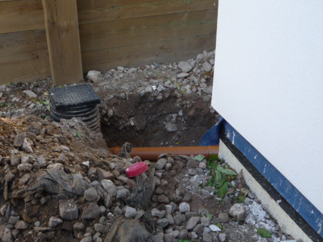
Imho any underground duct might be subject to condensation internally, more so if the cables run a bit warm. This could conceivably pool at any low point in the duct and affect and cable laying in it. I imagine this is one reason why any cable in a duct should be "duct rated". Paranoia? The regs touch on the issue of condensation, protection against moisture etc. The last bit of duct I ran I even considered running a length of aquarium tube in there so I could periodically pump out whatever, if anything, got in there. I even considered punching some drain holes mid point in the duct, wrapping in landscape fabric and packing gravel around it before concreting. Of course then I worried about the water table etc so in the end did nothing! I just ran everything in 20mm conduit and kept those together with some black dowpipe for neatness when concreting. Just noted that photo was taken in June 2014 @readiescards and it's still not finished! Tell your missus1 point
-
You have mixed potable (drinking) with non-potable (not drinking) water! The way you have it the boiler heats the UVC via a coil (Primary water non-potable), what is in the UVC is potable and supplies you domestic outlets. The UFH system is non-potable so cannot be run directly off the UVC you need a buffer tank as @Nickfromwales diagram shows. Alternatively if you want to run one tank then it would need to be a Thermal STore (TS) type where you heat the TS directly from the water (TS contains primary water), you take a tapping for the UFH from the TS (usually middle) and use Coils/Heat Exchanger for Domestic Hot Water (DHW). These have their drawbacks (heat loss). As you have a boiler the simplest is to add a buffer and plumb the UFH (upsize boiler if required). If you want an ASHP, then again it needs a separate buffer (though you can potentially not have one) and you should consider DHW pre-heat to take advantage of the high COP of ASHP at 40oC, however you system will be infinitely more complex (for a normal plumber). If you want to run the ASHP overnight for E7 then you will definitely need a descent buffer, to store adequate heat for the day (and DHW pre-heat if you go that route).1 point
-
/allegedly.1 point
-
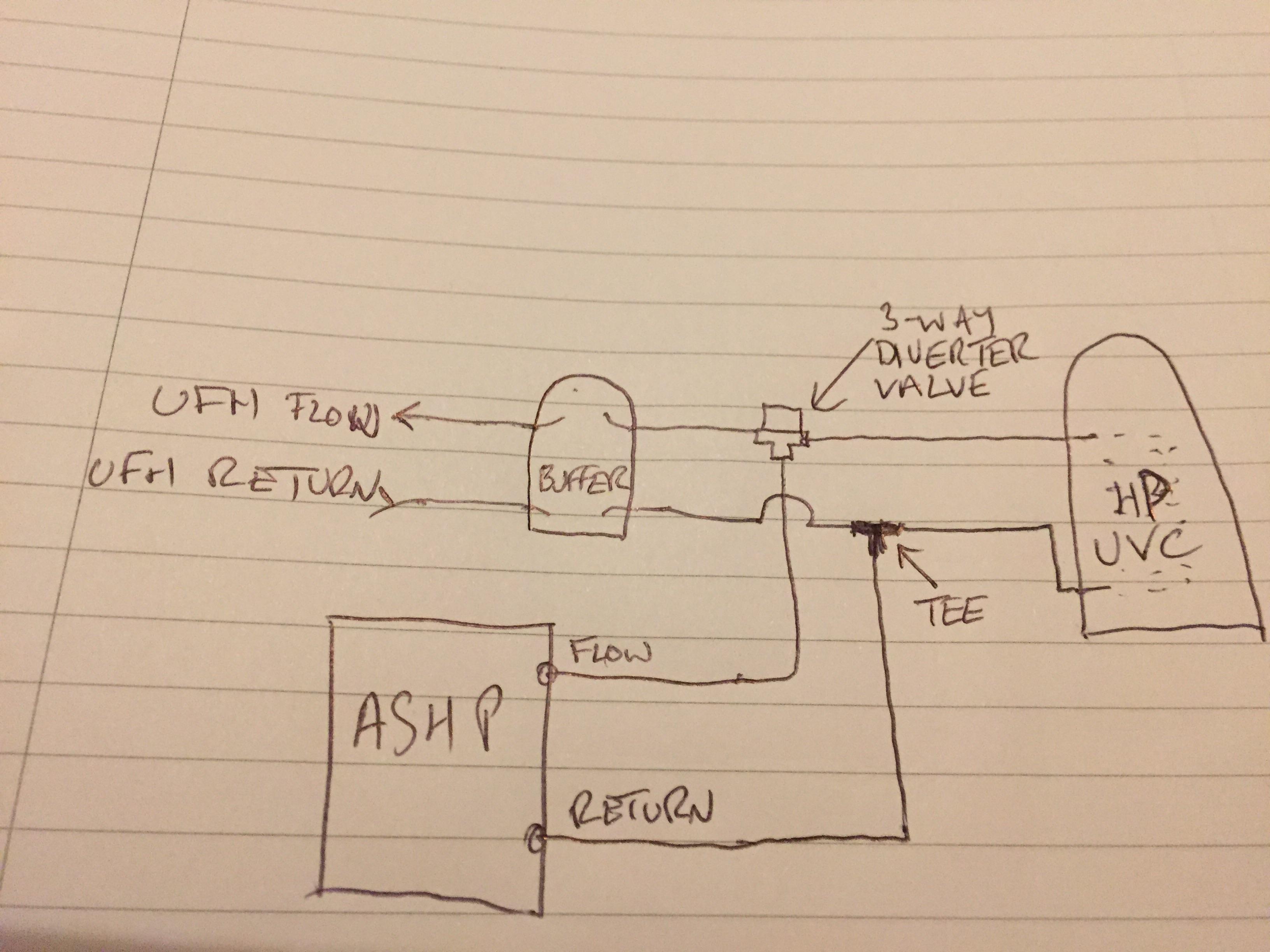
@Visti Rough as toast sketch. You can omit the buffer but its its better to have it in to help regulate the delivery from the HP and mitigate against short cycling when the house is up to temp.
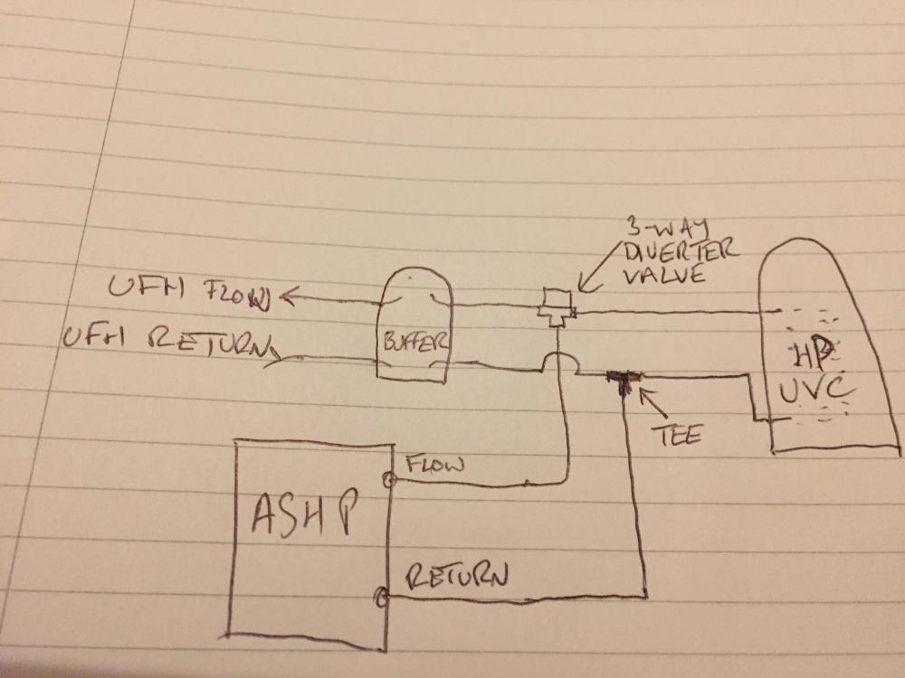 1 point
 -
@Visti UFH doesn’t work like that - it needs a 3 way valve and would be connected to the boiler if that is an unvented cylinder. You also don’t need an anti vacuum valve on an unvented cylinder - only used on gravity cylinders with high pressure pumps.1 point
-
I agree however packing behind those two hangers may be the only option to stop it twisting - you could do this with timber or even a split block but attaching that into a gap isn't going to be easy ! If that is a Wolf System or similar joist system floor then the trimmer should be the depth of the posijoist and the hangers should also be the same depth as the trimmers (if they are Simpson or Cullen) otherwise you will get the lower chord not being supported properly.1 point
-
Backing block is missing out of the trimmer where it meets the joists either side. Looks like the joists may have been installed back to front - usually there is a solid backer for the trimmer to sit against in the posijoist where the hanger goes. Without it, the trimmer will twist - doesn’t look to be double thickness either - and the centre posijoists will move. You could take the flooring up in front of the chimney section upstairs and do two things - pack behind the trimmer with a solid timber the full depth of the ceiling void - concrete screw through the trimmer to the chimney blocks behind. This would stop the trimmer twisting and give it some lateral strength.1 point
-
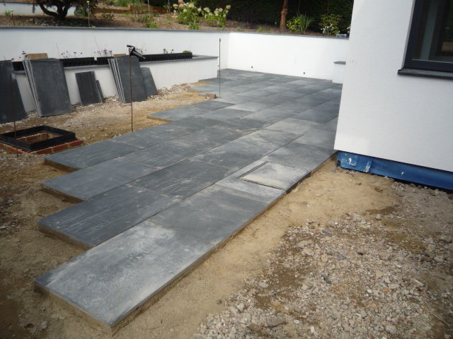
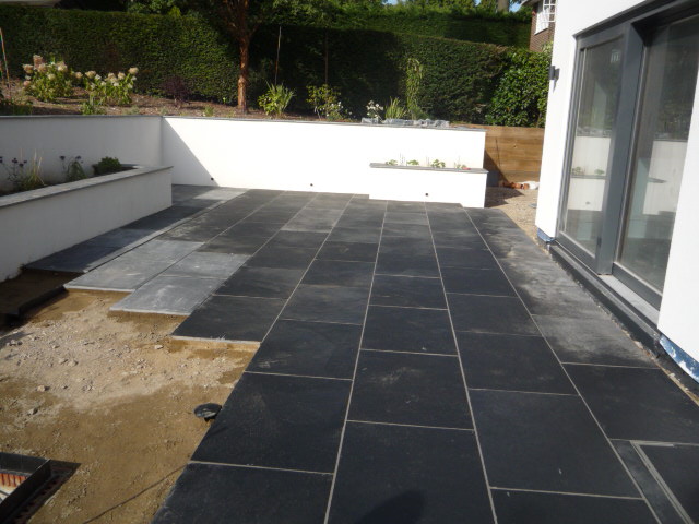
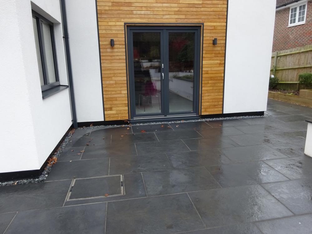
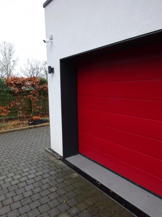
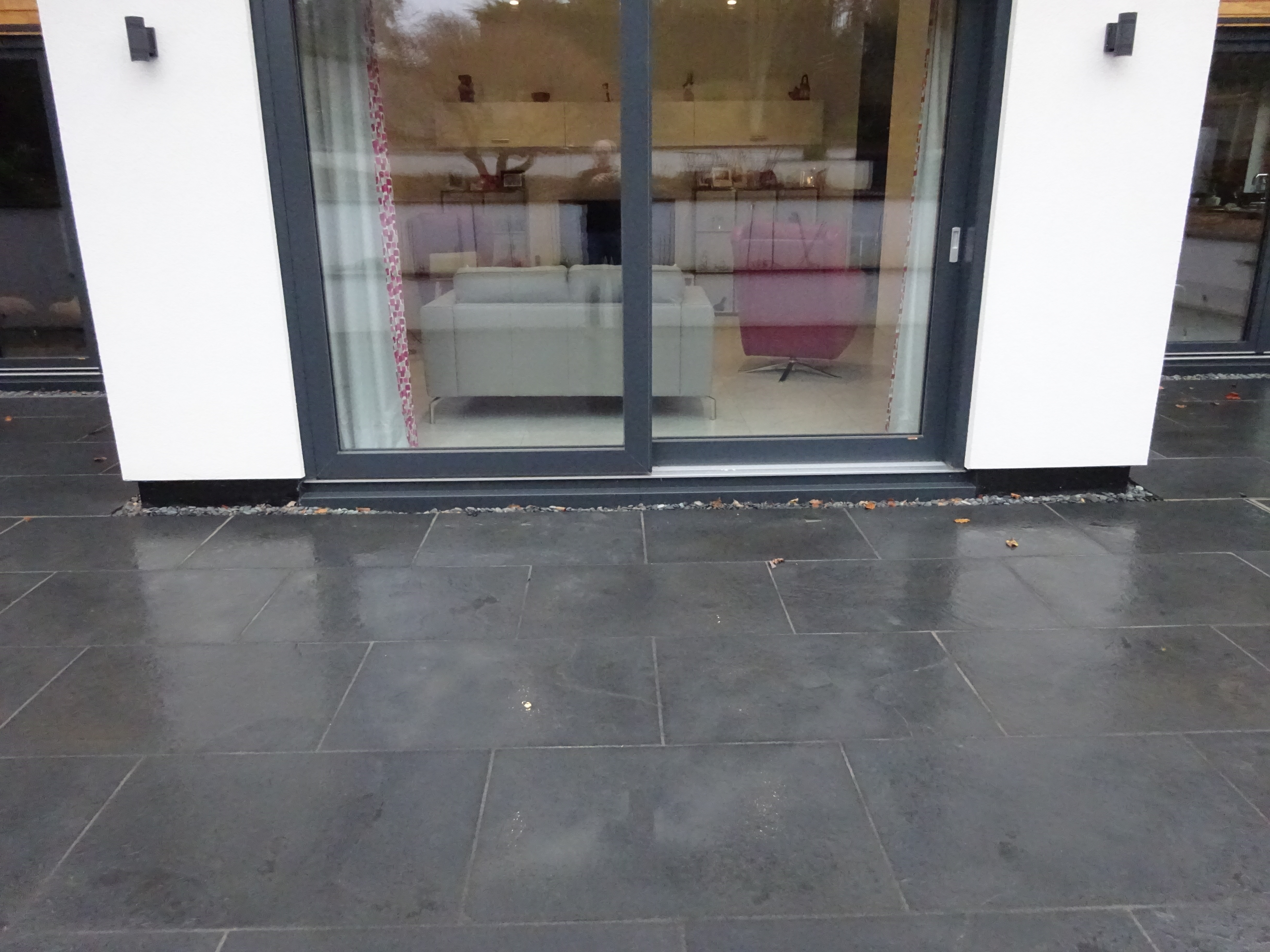
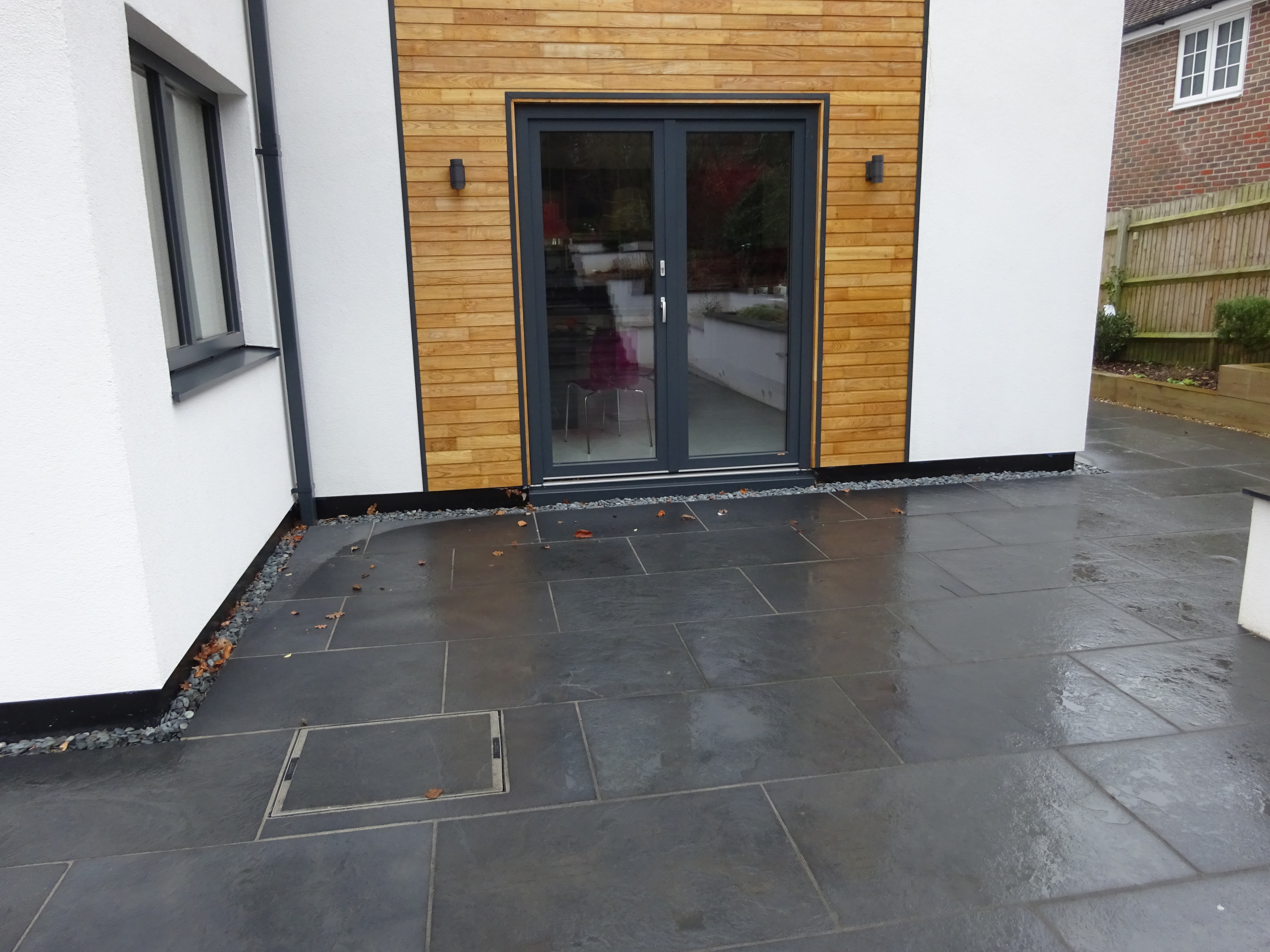
Great job -this is a very well considered detail and I wish I had seen it a couple of years ago when I was building my MBC house. I did ask around at the time and received various ideas. In the end I developed my own approach as follows: I installed an 300mm alumium flashing, it was actually the black powder coated aluminium roll used for seamless gutters but rolled as straight pieces with a seam rolled seam for strength. It seems to have worked out well - it is screwed and stuck to the EPS It was installed to form a flashing from underneath the external rendered finish , going across the soles plate and over the EPS to well below the nominal DPC level at which the extermal paving is installed. See the phot os attached, which should give you an idea. I had this flashiing made by the company that supplied and installed my seamless gutters, but they seem to be no longer installing seamless gutters and are concentrating on aluminium pressings , etc. I had some special aluminium flashings, coated to match the window frames, made for below the french windows/doors, ariund the garage doors etc. I attach some photos, during construction (though it at that stage still covered/protected by the blue external wrapping sheath used by MBC to keep render and other rubbish off the coating the flashing) and some taken today, to show the finished look. T

 1 point
 -
I know EXACTLY how hard it is to get good and reliable information on borehole and well systems here in the UK, as I really struggled with ours. I found that every single company that I spoke with, or used, except one, had some degree on incompetence, despite being supposedly experts. The one exception was a borehole guy who came out on site, had a very good look at what we needed, and what the hydrogeologist had recommended, chatted for about an hour or so and then was honest enough to say that really his expertise was mainly with boreholes in chalk, not gault and greensand and that although he'd be willing to have a go, he didn't think it was fair on us to use him when he lacked experience of drilling in this particular type of ground. We had endless problems with our borehole; the whole saga is in our blog, in several entries, but this will give a flavour of some of it: http://www.mayfly.eu/2015/08/part-thirty-seven-a-long-tale-about-water-and-life/ The treatment system design changed a fair bit after that, but that article probably highlights why I spent a lot of time learning about boreholes, drilling, pumps, water treatment etc! If you can take some photos then that would help a great deal. Most borehole stuff is made in Italy or Poland, with the very best pumps being made in Denmark, but they are expensive. Our Grundfos SQ 1-65 pump cost well over £600, which is a great deal more than the pretty decent IBO Polish borehole pumps that can be had for around £120 or so. As a near-zero cost experiment, you could, perhaps, just temporarily relocate the pressure vessel and filtration you have from down at the lower pump house to the upper one, replace the pump pressure switch with the one I suggested (you don't have to do this, but the optical ones are really nice and easy to adjust, and well worth the £20 cost!). You will also need to fit a non return valve down at the lower pump house, just as a backup, but for an experiment you can do without, as it's only really there to take the load off the pump intake valve, which may or may not be designed to take a continuous high back pressure (some are some aren't - our Polish pump definitely needs a non return valve on the outlet, the Grundfos definitely doesn't). The pipe lay out, from the bottom up, would then be: Pump riser pipe from the borehole to the surface (hopefully coming through a sanitary borehole cap, with screened breather vent) Optional non-return valve Tee piece with a 1/4" BSP female thread in the side port, for the pressure switch/gauge Optional drain cock Optional second non-return valve for servicing purposes only (see ** below) Pipe run up to upper pump house Pressure vessel installed in upper pump house, with a tee to the pipe feeding the filters. The filtration system you have (presumably a couple of jumbos - if they are not jumbos then you may want to think about changing them - see **** below for the difference). Output of filtration across to the house mains feed. When setting this up, to allow for the ~1 bar head loss between the house and the lower pump house, the pressure switch needs to be set 1 bar higher than the pressure at the house. I would advise setting the cut in pressure to 3 bar and the cut out pressure to 4 bar. That will then give you a range of 2 bar to 3 bar at the house, which is a reasonably good range of working pressure to have, and should give you a decent flow rate. One issue with the pressure switch is that it comes pre-fitted with two short 3 core cables. This makes installing it awkward, as they are rarely long enough to connect to whatever termination boxes you have (one for the pump switched power feed, on for the incoming power supply). My solution was to buy two pairs of these: https://www.tlc-direct.co.uk/Products/TLRC3.html fitted so that the plug is on the incoming power cable of the switch, and the socket on the outgoing feed to the pump, with suitable cables connecting another socket to the mains feed (make sure the power is isolated and checked to be dead before doing this) and a plug to the cable from the pump. This then makes life easier, as you can fit and tighten the gauge/pressure switch to the tee, then just plug the connections together. It's foolproof, as the connections will only go one way. Additionally, if you want to just quickly test the pump without the pressure switch (not recommended unless the pipe is open to flow water somewhere) then you can directly connect the pump cable to the power cable and switch on the isolating switch to check that the pump runs OK. As I mentioned above, this system also makes it easier to change the pressure switch if it ever fails, too. ** The idea here is to allow the short length of pipe between the second non-return valve and the first non-return valve (or direct to the pump) easy to drain down, without a flood. What this means is that you can turn off the power to the pump, open the drain valve to empty that short length of pipe, and change the pressure switch, or haul up the pump to change that, whilst the house still has a small reserve of pressurised water from the pressure vessel. It's a convenience feature, really, but for the relatively low cost of a drain valve and non-return valve worth it, IMHO, although I have to add that my view is coloured by having drained our system a couple of dozen times when I was battling to get it to work properly! **** The difference between standard 10" filters, long 20" filters and jumbo filters is very significant, both in terms of flow rate and filter longevity. Jumbos have a much lower pressure loss, and a greater filtration capacity and are just as easy to change. Here are photos that show what each looks like: These are the long and short jumbo housings, the canister part is around 140mm in diameter. They come in either 10" or 20" lengths, like the standard smaller filters. This is a standard 10" filter housing, it's around 90mm in diameter. This is a standard 20" filter housing. It's the same diameter as the 10" one, just twice as long. It doesn't have a significantly greater flow rate than the 10" standard filter, as it's quite restricted by the size of the head, but it does have around double the filtration life, from the bigger filter cartridge. We have two standard (10" high) jumbo filters. One is a 5µ pleated washable filter, the other is a carbon block filter. I've found that there's no noticeable pressure drop at all across these two filters, whereas when we had two standard 10" filters the pressure would noticeable drop when a couple of taps were opened at the same time. Hope the above helps, Jeremy1 point
-
That's useful, so you're losing at least 1 bar of head between the lower pump house and the house ground floor, perhaps 1.5 bar or so at the first floor of the house. The borehole is about the same depth as ours (ours is 53m) but what matters is how deep the water surface level is below the ground, as that determines how hard the pump has to work. In our borehole the water surface varies from between 4.5m below ground level to about 11m below ground level after I've had the pump on continuously at around 30 litres per minute, for a couple of days, to clean the borehole out. I have a beep tester (easy to make) that I periodically lower down the borehole to check the water depth, and every time I've checked it's been around 4.5 to 5m down. I don't bother checking now, as I'm pretty confident that the water level is always stable at around that depth. I did allow for it dropping to 11m below the surface when sizing things, just in case. If you can relocate the pressure vessel nearer the house, and adjust the pressure switch to get around 3 bar at the house ground floor level, then that should give you a fair bit better flow. I suspect the variation you may have seen has been a combination of filters getting clogged and maybe the pressure switch being adjusted for around 3 bar cut off down at the pump house. If the pressure at the pump house was adjusted up to around 4 bar cut off (raising the cut in pressure to suit) then that would give you 3 bar at the house, which is a pretty reasonable pressure. It's not too hard to set a basic system up, but it depends what you want to do, and how old the existing equipment is. You mention that the pressure vessel is horizontal, which isn't ideal, but is a configuration that is often used for low capacity combined pump sets. These rarely have a very large pressure vessel, usually around 50 to 100 litres (so about half that in terms of stored water under pressure) and often have a pump mounted on top. If the water level in the borehole is not far down (less than about 6m) then one of these pump sets will suck the water up from that depth, so there's nothing more than a suction pipe going down the borehole. Sometimes, a pressure set like this can be configured as a jet pump (a very common set up in the USA) where the surface mounted pump is manually primed when first installed, and has two pipes going down the borehole. One delivers a low volume, high pressure, supply to the jet pump, the other is the outlet from the jet pump. Jet pumps are eductors, with no moving parts, which is one reason that have been popular, but they aren't very efficient, and will rarely deliver a very high pressure and flow rate. Nowadays it wouldn't be usual to fit a set up like this, with a jet pump, as there are plenty of reasonably priced and reliable submersible pumps around. If you have one of these then the give away will be a cable going down the borehole alongside the pipe that delivers water, plus (I hope!) a safety rope to prevent the pump falling down the borehole (it does happen.........). If it were me, and I wanted a more stable supply at the house with a better flow rate, then I'd look at fitting a pressure vessel of around 300 to 500 litres capacity at the house end, perhaps in the old pump house. I'd also fit the filters at this end, too, after the pressure vessel and before the house supply. At the borehole end I'd fit a non-return valve (in case the pump one fails - they do, and it then causes the pipe to drain back slowly) and then an optical pressure switch. I've found a very affordable Chinese made unit is very good indeed. It has a pressure gauge, with two movable pointers that are set by screws to the cut out and cut in pressure. They are so cheap that I bought two, and fitted them with three pin plugs and sockets (the ones used for extension leads for garden tools) so that I can quickly change them over if I ever get a fault. They are sold via Ebay, and these are the ones I have: http://www.ebay.co.uk/itm/151020-Automatic-Water-Pump-Pressure-Controller-Electronic-Adjustable-Switch/272751286212?epid=703592864&hash=item3f813e57c4:g:GCIAAOSwRvdZZOae They have a standard 1/4" BSP male threaded port at the bottom, with an O ring seal, so are easy to fit in place of the spring controlled ones. They also have the advantage that they don't freeze up in cold weather, unlike the spring ones.1 point


This leaderboard is set to London/GMT+01:00