
ProDave
-
Posts
30857 -
Joined
-
Last visited
-
Days Won
427
Everything posted by ProDave
-
I must admit I was thinking copper for the 10mm run, no restrictions at joints (soldered) High mains pressure so I expect the hot water to be running at 3 bar from the PRV.
-
What thickness of EWI? My house is clad in 100mm thick wood fibre, and the standard Rationel cills work by putting the window frames half in the timber frame of the house, and half sticking out to then be encased in the wood fibre board. P.S I think the fitting of the cills is the one "bad" feature of the Rationel windows. They fit by being "pressed" into a slot in the bottom of the window frame. The builders didn't want to fit the cills to the windows before fitting them as most of them went in from the inside and the cill would be in the way to do that. So it was down to us to fit them from the outside afterwards. One of them in particular took some serious hammering with a hammer and block of wood to get it to go in. Nervous moments hitting the bottom of the window frame (in effect) very hard with a hammer.
-
I would say a SE is needed if there is a retaining element. I am building my house on strip foundations. One of my design briefs to the SE and architectural technician was I wanted "simplified" foundations. A lot of timber frame companies will design a house that uses thin joists on the ground floor and then a lot of intermediate sleeper walls to support them. I took the view that I need thick joists anyway to get enough insulation in (I am using 300mm JJI joist) and the first floor joists (posi joists in my case) are capable of spanning the distances in one go, so there is no reason the ground floor ones can't also span the same distance without intermediate sleeper walls. One thing others will warn you about is what happens if the timber frame arrives and it does not fit? Who is responsible? I solved that problem by contracting one building firm to build the foundations, and construct and errect the timber frame. If it didn't fit, it was entirely their problem to solve. As it happened, the joiners came to measure the foundations before building the frame just to make sure the ground workers had got it right.
-
I will be doing the same, 16mm leftover bits of UFH pipe from the last house, using the 16 to 16mm adapters at each end. The flexible pipe will wind its way through the posi joists, converting back to copper in some accessible point for the final conections. I don't want any hidden joints. I doubt I will actually use a true manifold. The objective will be the absolute shortest possibler route from hot tank to hot taps, and I doubt that will be achieved with a manifold, rather just branches off a backbone pipe with individual isolators. For the long run to the kitchen tap, I am going to install a parallel 10mm pipe. Only when I try it will I find out if the 10mm pipe delivers enough hot water flow to the kitchen tap. If it works, that's a lot of wasted volume saved. If not the 16mm pipe will be there to swap over.
-
I don't understand that "borehole view" on that geology map. Can you explain why there are a lot of "boreholes" all along the A9 road, where there are no houses? And the one real borehole that I know of nearby is not on the map. One of the estates in town appears to have about 100 boreholes, yet is on mains water. It doesn't make sense.
-

A Timber framed house with external wall insulation
ProDave replied to ProDave's topic in Timber Frame
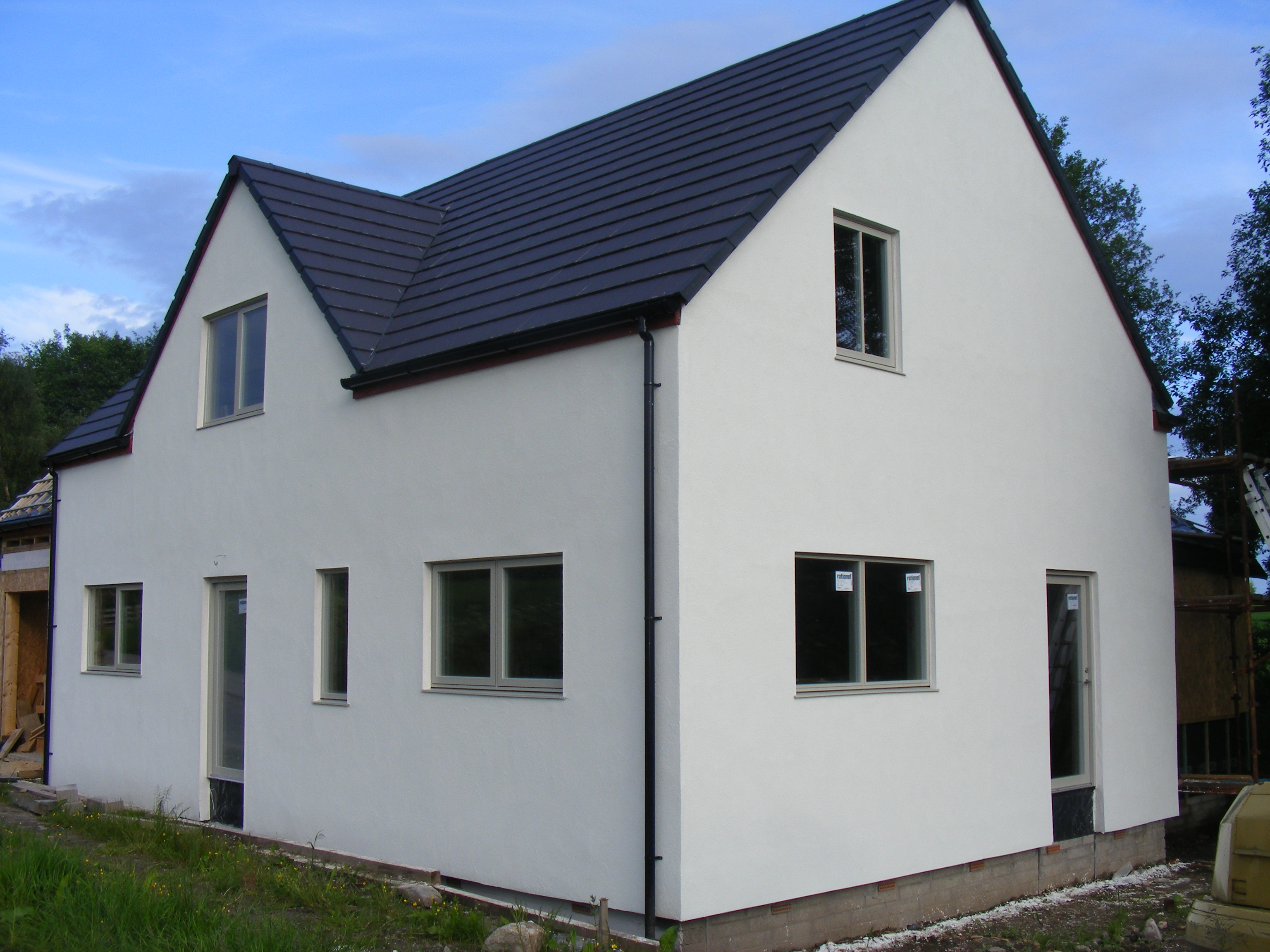
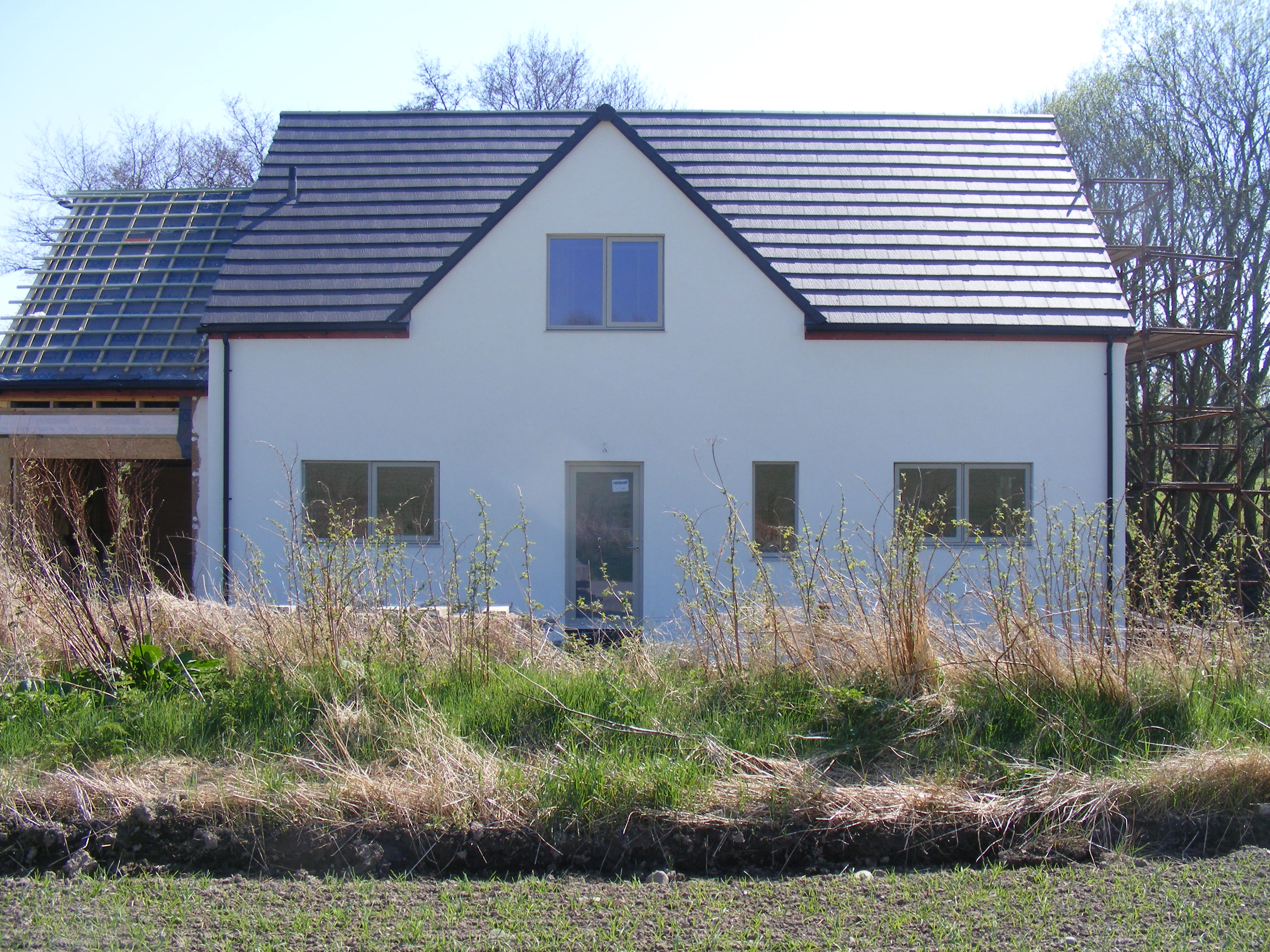
Another wall has been rendered, and it's really starting to look like a house now. More on my blog at www.willowburn.net, look for the blog entry "More cladding and rendering"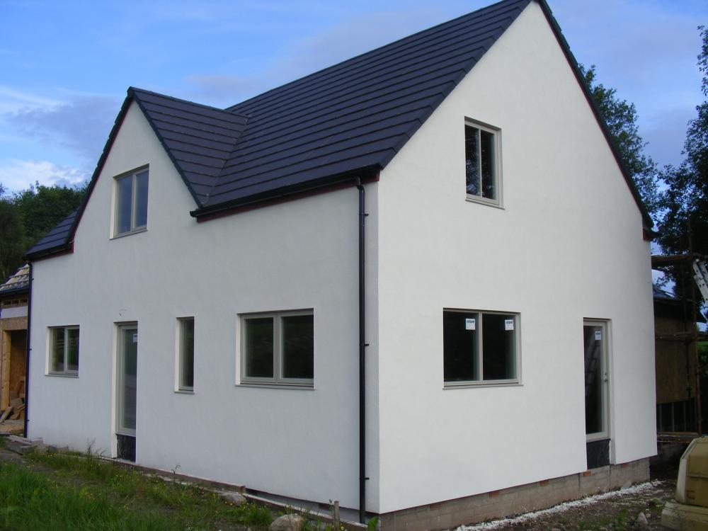
-
I think that's a good machine. I haven't used one myself, but a local ground works contractor has one, and it was used to dig the foundations of my present house. It is currently sat in next door's garden having installed his treatment plant earlier in the week. I would go and have a look, make sure it runs okay, check for leaks, check how much play there is in all the joints etc. The only difference is the one my local contractor has is on rubber tracks. That one is on steel tracks so it's probably older. Steel tracks last longer and seem to be harder to throw a track off, but they are somewhat unkind if you want to travel along a tarmac road in anything other than a straight line. My little 3 tonner has steel tracks so I wouldn't let that put you off.
-
Your second link is the type supplied as standard by Rationel.
-
Size of Minidigger to remove Treestumps
ProDave replied to Ferdinand's topic in Landscaping, Decking & Patios
This was the largest tree I removed: The one on the right. the trunk was about 18" diameter. It was very hard going with my 3ton digger. I had cut it off about 4ft above ground so I had a good stump to work with. It still took a lot of digging and pushing and pulling. I found the maximum "push" was achieved by positioning the bucket then pushing by tracking the machine forwards. That seemed to give more force than just trying to push it with the boom. Your difficulty is going to be the short stumps, so it will be more a case of dig them out rather than the brute force of push the stump over.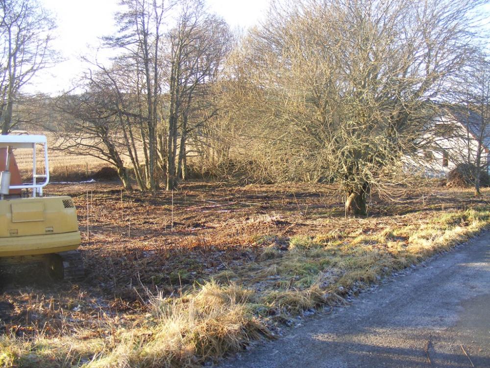
-
There's actually something cute about that little bungalow, almost a shame to knock it down. Before I bought my first house, there was an opportunity like that, a tiny little wooden bungallow with PP to knock it down and rebuild. It had an external brick chimney that was leaning away from the rest of the house. That was when my bubble was burst as everywhere I tried said they would lend money to build a house, but I could not find anybody that would lend the money to buy the site. Hence it was almost 20 years before I got to do any of this self build stuff.
-
Fred Dibnah did this. He dug a ventilation shaft the "old way" building a brick wall round it as he went. Dig a bit more out then lay another few rings of bricks underneath what was there, then dig more etc. Re Dowsing. I beg to differ. Have you tried it? I was your average skeptic until I tried it when visiting my BIL at his farm. He gave me his dowsing rods and said "walk across that yard" and part way across the two rods swung together. "That's a water pipe" says BIL. I got to try it in anger for my water conection. The contractor couldn't find the water main, it was further into the field than the plans showed. They were on the point of giving up so I went and got my dowsing rods and walked slowly into the field. About 1 metre further than they had dug the rods swung together and when they extended the trench there was the water main. If you actually hold a set of rods and try making them come together, you have to tilt them quite a long way, so you can't "trick" it. When they do "detect" something, they come together without you moving them. Like I say I don't even begin to understand it, I just know it works. Re the blindfold thing, perhaps you need to see for it to work? A friend of my BIL says he can see underground springs as a green hue on the ground and thought everybody can see the same as him.
-
Our well was about 20 feet deep. I never saw the water lower than 15 feet below the surface. If I dug one here i wouldn't need to go any more than 6 deet deep, even in summer. I once went down the well to drill the holes for the garage rainwater pipes from the inside. Just lowered my aluminium ladder down and descended it, complete with electric drill and an extension lead and drilled the hole. Someone afterwards told me that was a very stupid thing to do for a number of reaons.
-
Are you suggesting you dig a well or borehole as being a cheaper option than fixing the leaking main pipe? My previous house, a 1930's semi had a well. It was only a shallow well and it drew water from the water table. It was no longer in use being on mains water by the time we bought it, but local knowledge said the well in our garden fed 4 houses and the pub across the road. Water being drawn up by a hand pump in the scullery. The number of pipes leaving the well bore that out. It was very interesting to look down it at different times of year and see how the water table had risen or fallen. I did install a pump down it and used that for watering the garden. Later when I built a garage, I piped the rainwater from the garage into it as a handy soakaway. I wonder if that was SUDS compliant? If you want to know about dowsing, ask. I found I can do it. Please don't ask me HOW it works, but it does.
-
When I was down south and we had an extension built (of masonry) it was normal pratice there to bed a wallplate on mortar, so it was fully supported. Up here sole plates and wall plates are fitted "dry" to the top of the wall / Foundation. I wonder why?
-
We had a "similar" issue. but it wasn't because the foundation walls were not flat, it was the timber for the sole plate came from the merchant warped. The builders bolted it down as hard as they could and still it was clear of the wall in places. It wasn't until it had more weight from the frame on it that it finally "bent" itself flat. Timber, don't you just love it as a building material?
-
Council tax valuation bandings
ProDave replied to Calvinmiddle's topic in General Self Build & DIY Discussion
Ours was quite simple. I submitted my appeal, having found a number of similar sized houses for sale that were two bands lower, so a 2 band reduction is what I asked for. The council did not agree so it was set to go to a hearing, where I would be given the opportinity to present my case as to why I thought it should be lower, and they would present their case as to why it was the band the originally set. The day before the hearing I received a phone call offering not to go to the hearing and they would reduce it by one band, which I accepted. -
For a temporary fixing of the bottom of the membrane, don't nail it directly, fix it down with a batten nailed through and leave the nail heads a bit proud so you can pull them out.
-
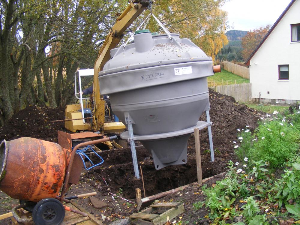
The issue of "anchoring down" the tank was one thing that made me chose the Conder. It has built in legs and the ring around the bottom. So it sits unaided in the hole while you pour enough concrete to encase that ring to anchor it down. Some of tha alternatives that had various anchor kits, seem to involve someone going down into the hole to fix parts of the anchor kit, which frankly sounds a VERY dangerous exercise.
-
When I tried Sketchup I just found I had no idea of scale, I didn't know if I was drawing a microdot, or something the size of the moon. And trying to draw two lines that touched but not overlapped seemed beyond the wit of man. I use ORCAD, which is an electical circuit CAD program. I have been using it in one form or another for more than 20 years, originally runing under DOS and when it migrated to Windows kept pretty much the same look and feel. I guess the difference is I know it inside out. In my last job, just before I left, they switched to an electrical cad program based on an add on to autocad. I HATED it. Everything was so clumsy and imprecise, just moving a few wires around was a chore. And that's how I found Sketchup. Orcad is pretty lousy for ordinary drawings, but at least I can do something in it very quickly.
-
I tried Sketchup, I just could not drive the damn thing. Nothing at all about it was the least bit intuitive and I just couldn't get it to do anything sensible. Perhaps I should try harder? Or I'm to old and set in my ways.
-
The start of the renovation story.
ProDave commented on TheMitchells's blog entry in Scooby Cottage renovation.
If you have to replace the floor joists, is there any merit in using steel? You can get the strength you need in a much smaller thickness. A nearby pub is doing this where they need to lower the floor level of a bar they are renovating to enable wheelchair access. Lowering it and keeping wooden joists would result in insufficient headroom in the cellar. So instead they are installing a set of steel floor joists that lower the floor level while still keeping enough headroom in the cellar. I take it the second picture shows a single storey rear extension to your house that takes up all but 6" of your back garden? -
Yes that's about it. What are you using to draw that sketch to do it so quickly? TP sell those eaves trays dirt cheap if there is one near you? (don't think there is much "near" you)
-
Yes I admit the picture might be hard to understand. Start with a sloping roof with your cross battens on to support the box profile. your bottom batten say 6" up from the bottom of the roof slope. Now lay something down the roof to represent the box profile roofing. Offer up your fascia board, with a vent strip on top of it and set it at a heght that almost touches the underside of the roof sheeting (small gap to allow for the infill piece) Your fascia board will of course now be higher that the bottom of the slope. This is where the eaves tray comes in. The eaves tray fixes to the top of your fascia and creates the kick up slope to meet the main slope of the roof. This tray is made of plastic, and the joint between the fixing and the main part of the tray, is scored, so you can pre bend it to match the angle it has to be at. Once you have done that mock up you take it all apart, lay the eaves tray first, then the membrane which now kicks up on the tray and over the edge. then fix the vent strip to also fix the bottom end of the membrane, then fix your battens and counter battens. Making any sense yet? If it wasn't hissing down I would go and try to get a better picture.
-
What is wrong with the way I am doing it, in post #6? the bottom horizontal batten is only about 6" up roof so I don't think it will leave much flapping in the wind. Your roof is going to be so high compared to the gutter, I would be worrided the water might miss the gutter.
-
Old (~1970) black MDPE water supply - which connectors?
ProDave replied to DavidWright's topic in General Plumbing
There's this at toolstation, http://www.toolstation.com/shop/Plumbing/d20/MDPE/sd2729/Metric+to+Imp+Conversion+Kit/p51455 Looks like a replacement set of inserts to convert a metric fitting to take imperial pipe. Use two of those and a metric tee and your new branch will come out at metric size mdpe. Buy the fittings and check again with your vernier that it is the right size before cutting the old pipe. If you later want to disconnect the original supply point, either fit a stop end plug into the tee, or replce the tee with an elbow fitting.