ProDave
-
Posts
30680 -
Joined
-
Last visited
-
Days Won
424
Everything posted by ProDave
-
I don't like the earth wire under a fixing screw, should have used the Banjo's and nut and bolted the earth through those.
-
Dirty water submirsible pump. If there are ANY stones, get one with a stainless steel impellor, not plastic/
-
Mount a steel adaptable box immediately under the CU. Gland the SWA into that, bring the inner cores into the CU along with the earth tail from the glanded SWA in the metal box.
-
Which is why in my case they had really wanted their cable under my garden and that is what they offered, I would not have signed.
-

Converting an internal cavity wall to single skinned
ProDave replied to david86's topic in Building Regulations
Devil's advocate here, but it is only the first 2 or at most 3 joists that get intermediate support from that small wall. The rest of that room the joists span all the way with no intermediate support. I am willing to bet you could take that little wall down completely and all would be fine, but best to get a SE just to make sure there is not something silly like a joint in a joist on top of that wall. -
I was approached by a wind farm about laying an underground cable across my garden. I played along for a short while more curious to see what level of payment they might offer. But I really sis not want a 33KV underground cable across my garden imposing restrictions on what I could do with that bit of garden unless they offered a high figure. I got as far as letting one of their surveyors measure the garden and they concluded as I had, it was not the easiest or best route. I understand that cable is now going under my neighbours garden alongside another one laid 10 or more years ago. From what I gather from him the payment is "not a lot"
-
Single fixed output temperature, unit only advertised for HW production. It would probably take some bodging to make it work with space heating as well and the fixed output temperature would be too high for UFH. And no mention of soft start or inverter so assume not.
-
I would run a mile from that one. Very cheap very basic unit likely to disappoint.
-
New circuit? old circuit? Do "real" high power loads work or do they trip as well?
-
Just started a self-build in Dorset. Exciting times!
ProDave replied to NailBiter's topic in Introduce Yourself
5ACH is poor. You should be targeting less than 1ACH and MVHR should be considered a must have. If your architect does not understand MVHR you need to find someone that does. -
Just started a self-build in Dorset. Exciting times!
ProDave replied to NailBiter's topic in Introduce Yourself
Am I reading that right? 114 panels each rated at 600W. If so that is a total peak output of 68 kW That like everything on this build is 10 times what could be considered "normal" First best of luck in getting the DNO to allow a 68kW grid tied solar PV system on a domestic connection. Then just how do you propose to self use anything other than a tiny portion of that in the summer? -
I am just exploring ideas to overcome what appears to me to be a stupid rule. Leave a gap (nothing to say how big the gap is) and it is a side extension only. Dare to join it to the back of the garage and suddenly the 8M limit kicks in. Stupid idea no 2: Build a very small PD rear extension on the back of the old garage just enough to provide the new access passage. Then adjacent, but not touching that build your side extension for the rest of the build. Because it does not touch it is only a side extension and the silly 8M limit does not kick in.
-
Okay so you are being hit by this clause: ? If your side extension did NOT join the back of the garage, but left a very small gap (I see no floorplan reason that it must actually join the former garage) then it would be JUST a side extension and you would get the 10 metres you want.

-
OK I keep coming back to this, as I am interpreting this very different to most people. All comments re wanting a 10M extension but only just being able to squeeze to 8M under certain circumstances, says you are treating this as a REAR extension built onto the back of the original garage. If that is how you interpret it then indeed you would be right. However to be it looks obviously like a SIDE extension built onto the SIDE of the existing house. Yes that als means the right had side of the extension also touches the back of the garage. In the case of a SIDE extension, it's depth (how far you can build out from the existing side wall) is limited to half the width of the original house. Your drawing suggests you are within that, but it might be marginal. So first go and accurately measure the width of the existing house where you are joining on to it, halve that figure, and ensure your side extension is no more than half the original width. You might have to make a small compromise the depth to ensure it is no more than half. Any such compromise would ease the pinch point at the boundary. Treating it as a SIDE extension, i see no limitation on the width of the extension (the 10M figure) as long as the extension does not project beyond the end wall of the house. The only PD limit I can see that will bother you is you will be building withing 2M of the boundary so will be subject to an eaves height of 3M. That might be challenging, but certainly worth looking to see if you can find a solution. As I see it, persisting in making it comply with PD removes the planning scrutiny from the narrow boundary gap issue. The crux of the matter hinges on this being an extension that fits into a corner, so is is a side extension, or is it a rear extension? Which set of rules takes precedence and why?
-
I don't think the 10M length is a problem. The limits on a side extension under PD appear to be the width, which is up to half the original width of the house. However the issue I see is the proximity to the boundary fence. I think that could be a big issue for planning. With no dimensions it is just a guess but it looks to me the gap between the extension and the boundary fence is tapered and very thin at the bottom end in that drawing. I see an issue with how do you build it, and how do you get access to maintain it. Planners might not be happy with that situation.
-
Ask on TEF? The founder SBS Dave sold the business some years ago, so it looks like the new owner has thrown the towel in.
-
It would help of the OP provided a sketch. My guess is he is converting an existing attached garage on the side of the house, and building an extension behind the garage the same width of the garage. That ought to be PD within some limits so what makes him think it is not?
-
That switch has a reed switch. It would not be my first choice. Though it does say it is rated for 3A which ought to be enough, and the usual trouble with reed switches if you overload them is the contacts weld shut.
-
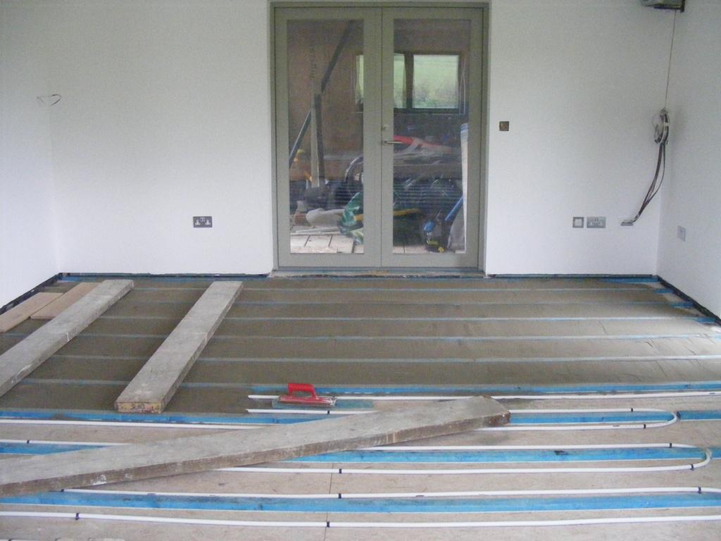
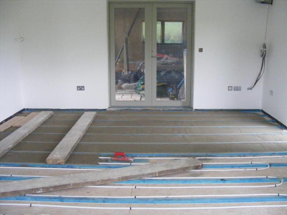
Yes to support the pug mix and to fix the UFH pipes to.
-
You should not be dropping 20V across the switch. I suspect a wiring / measuring error somewhere. Especially as you are getting similar volt drop with the new switch. Post some pictures of where you are taking your measurements and with what. Is it a real flow switch (I have seen some strange setups with a thermostat acting as a flow switch)
-
Do you really mean a 10M wide side extension? That is wider than most houses?
-
I used 300mm I joists. 300mm Frametherm 35 between the joists. Then air tight membrane taped and sealed to the building walls. 12mm OSB. Battens following line of joists. UFH pipes between battens, dry pug mix for heat dispersal, then finished floor (engineered Oak) Design joists for the extra dead load of the pug mix and allow for the height build up.
-
Rendering over Knauf external insultation
ProDave replied to Walshie's topic in Plastering & Rendering
What type of insulation is it (link?) -
I read the issue as lack of sufficiently talented people. He might be a brilliant joiner, but to design it such that to replace a switch you have to remove the whole think is just lousy design. I am sure you electrician could have designed the location of the switches better than that, but he is not a joiner and not making the cabinet. And this is the problem when you ask 2 different trades to contribute to one finished product. When there is a problem, they will each blame the other and you will get no satisfactory resolution. I know on this job your expectations and standards are high, there is nothing wrong with that, and sadly it seems they have been unable to meet those standards. The only way to determine if it is an installation problem (the "bodged" joint) or an equipment problem (either a dodgy switch or a dodgy LED strip) is by substitution. I bet nobody is offering to do that? In a perfect world you would have been able to get the cabinet, with lights fitted, supplied and installed by one person with a performance guarantee on the end result. And there is you lack of skilled people because nobody would offer that. I am in fact doing this with a neighbour. He has a brilliant German cabinet maker building the shelving unit and I am installing the lighting. We are of course testing the lights are up to expectation before installing them.
-
I am not convinced the issue is the soldered connections instead of a plug in connector. Before installing and connecting the strips I would have given them a dry run on their own to make sure the light they give and the startup characteristics are to your satisfaction before fitting them into the cabinet.