


Gus Potter
-
Posts
2310 -
Joined
-
Last visited
-
Days Won
29
Everything posted by Gus Potter
-
Hello Tammie. Good post. My view is that to get the best out of this site you maybe want to provide a bit more basic information. For example is it a new build? Is it a timber framed house or a more traditional type of construction.. your survey /home report / sales brochure may help here in that it may tell you what kind of house you have. If you wish you can give a bit more detail, where you are located in the country and just some back ground information. Try if you can to describe the symptoms in more detail. I think if you do this there are a lot of folk on this site that will chip in and help. I learn something new all the time here.
-
What type of joists?
Gus Potter replied to osmononame's topic in Mechanical Ventilation with Heat Recovery (MVHR)
Hope this helps when choosing your joists, maybe thinking about deflection / strength of floors / cost and engineered type joists or solid timber. Roughly, if you weigh 100kg the joists will bend by X amount when you stand on them. If you put on a 50kg rucksack they will bend by about 1.5 times X roughly 50 % more. Remember that they will have bent a bit during construction due to their own weight and the floor / ceiling / services you install hence my approximation. But very roughly if you have joists at 600mm spacing and you reduce the spacing to say 300mm you will reduce the extra deflection due to walking about and so on by about half. The cost will increase as you need more of them and possibly more strutting / bracing etc. To get the best out of things.. Imagine you are working in the pricing depatment of a timber frame outfit. You may do tens and more quotes a day, many of them small and with not much financial motivation. You could get a bit bored after quoting the tenth domestic floor job? However, if someone gets in touch that has clearly put a bit of effort into understanding what they think they might need, phones up and says they need help but have tried their best to get to this point, then often the flood gates will open and you will get a lot of help, maybe a better price too! We are all human after all. For the very keen.. Maybe think about the benefits of having a slightly thicker floor in terms of cost and practical space to get all your services in. As an alternative you can increase the depth of the engineered joists / or thickness of the flanges and this too reduces deflection. All other things being equal you can do a qualatative analysis just to give you a feel for things. You don't need to know / calculate the loads etc you just need to know what is called the second moment of area of the joist. You can often find this in the manufacture's property tables for engineered joists. The second moment of area (units often mm^4 / cm^4 or m^4, does not matter so long as you compare like with like) is partly a function of the depth of the joist.You will be able to see how it rapidly it increases with a small increase in joist depth or introducing a thicker flange on an engineered joist. The higher the second moment of area roughly the less the deflection. There is another kind of deflection called shear deflection but we are just trying to get a rough feel for things at the start. If you are looking at the tables just make sure you have the axes correct. Under the British Standard notation the value you want is the Ixx direction. Under the Eurocodes which most data is now presented in the vertical direction is called the Iyy direction. Again and roughly if you increase the second moment of area by say 20% you will reduce the deflection proportionally . There a few other things to consider but at the early concept stage this can be a very useful tool to give you a feel for things. -
What type of joists?
Gus Potter replied to osmononame's topic in Mechanical Ventilation with Heat Recovery (MVHR)
Hi all. For the self builder here are a few practical observtions. Can anyone else chip in? If you are self building your frame will often be out in the rain a lot longer. Engineered joists require a lot of other stuff to make them work and you need to know how you supervise that to ensure you have all the other bits that make a long span Engineered Joist work. One reason they are cheep in terms of spanning is that they they are working a lot harder / efficiently, they rely much on bracing, stiffeners and so on. In summary, they are very much less forgiving than a solid bit of timber. There is a big difference between the self build and the major house market. If you are self building it maybe takes you longer. Also, you could be employing a general local builder rather than an experienced specialist kit erector with all the site / quality controls in place... yes there are many large house builders that don't deliver on this. Say you have an Engineered joist where the web is glued to the flange... then although the manufacture's say they use water proof glue they caveat this a lot in terms of what you need to do to look after them during construction. Perhaps take a 1.0m length off cut of a glued Engineered Joist, soak it in a barrel a few times to reflect a self build application, take it out and hit it with a hammer... then decide if that is the right thing for your application. You may find that the flanges separate from the web pretty easily. The ones with the metal webs are essentially mechanically fixed and seem to be a bit more forgiving in terms of the self build where things might be out in the rain longer. Russell makes a good point on the deflection /vibration so consider his advice. A 10.0m span is not small so be very careful! In summary, sometimes for the self builder perhaps look at your own circumstances in terms of budget, programme and then match the materials to give you the best outcome and reduce your financial risk? -
Worth a thought..great stuff from "self build on Skye" They are nearly finished and already enjoying life. I built the garage first with a shower, bog etc and old second/ third hand kitchen that someone was chucking out. Slept in a 14 foot caravan next to it so planners didn't boot us out.. going back a bit now . Installed the bath well before the first fix, a cylinder with an electric heater, just a wind and water tight shell. Still remember having the first proper bath in the dark in my own home...and I needed it! It's these wee things that keep you motivated and your head up!
-
I need to go to spec savers. Can't see the generator.
-
Yes you are not far off the mark that is is a steep learning curve. We all make mistakes, even the "pro's". When you do, prepare to pick your self up and march on. It will be hard at times and every project is differant. If you put in the work things will go better at times than you expect, so look forward to that also. We talk about luck? Seems to me that the folk that put in the work into the research and consider advice seem to be a bit more lucky in general..just and observation. There is however a another bonus in this. You tend to get a home or say an extension that belongs to you, no one else has the same! Maybe adapt what you read here and make it your own. There are a lot of folk on this site that have extensive knowledge and experience so they can really help you form a balanced view. When you get stuck they will make time to help you. Remember, it's your project and your decision so you maybe want to take as many views as you can, and make what is called an "informed client decision" This is still one of the few sites that are not commecially driven (at least I think this for now). The "structural side" of this is my thing and I try, if I can, to chip in. Make the best you can of this site. Digest the information you get here and make your own informed decision. Take that approach and it will serve you well. All the best. Gus.
-
Well done. Try and find some time out to be proud of and reflect on your achievement. That will be hard to find as by now you'll have realised that island living is very rewarding, socialble and a great place to bring up kids. All the best.
-
For the DIY er that wants to build say a small wrap around extension, dodging away at the weekend and wants to keep hire costs and trips back and forward to the hire shop down. Thanks Tonyshouse. To quote Tony. "A piece of orange string, set out front of building first then the critical side square to it then c/l of trenches then the rest of it I mostly used ancient Egyptians 345 and double checked by measuring the diagonals os any rectangle" Levelling. What about a water level. Get a garden hose & some clear plastic tubing say 2.0m long from the DIY store. Couple 1.0m of the plastic tube to each end of the hose. Get some food dye. Choose your own colour – just make sure it is a darkish one so you can see the water in the clear tube. Get ALL the air out the hose. Calibrate it by putting the two tubes together – the water in each should be at the same height. Jiggle / shoogle / do something to it and check again. Pin one end of the clear tube to something and take the other end to where you want, just make sure the water does not spill out. Mark the levels of the water to the bottom of the meniscus. Now you have a datum and you can measure up or down from that. Change the tube ends round and check again to give you confidence it works. Lastly, when you are finished plug the ends of the tube to preserve the coloured water. The great thing about this is that it goes round corners and as many as you like. A laser beam goes in a straight line unless you can apply some physics I think. You can take it into the house to check the floor levels to tie say an extension in... probably plug the ends first in case you get dye on the carpets. No points for that! Setting out dimensions For smallish stuff invest in a good steel tape, fabric ones stretch very easily without you knowing. If measuring over a distance use blocks, wood or something to support the tape frequently so it does not sag and try and keep the same tension on the tape each time you take a measurement. Set out and double, triple check. If you take your time you’ll get will within the tolerance a bricklayer can build to. You can use Pythagoras (3,4, 5 triangles to get a right angle) there lots of school maths formulae you can use to calculate the sizes say if you know the length say two sides of a triangle and the angle between them. Hope someone has fun with this and saves a few quid.
-
hyload or 'normal' (eg visqueen)... whats the difference?
Gus Potter replied to sean1933's topic in Damp & DPCs
Hi Sean. All Engineers make mistakes from time to time, leave something off a drawing, a small note for example... say your DPC. They are all human! Give your Engineer a call, most are happy to have a Client that has actually has taken the time to study their drawings. A lot of Engineers spend a lot of time thinking before they produce the drawings. Lots of folk don't appreciate that. If you phone them up and talk to them you will probably get a good response and some extra free and cost effective advice! -
Hi Joe. In reverse order. To quote you “with regards solar panels they must be “fit for purpose” so the wind load calcs must have been done, different if you just did a DIY job.” I think you have touched on a good point. I agree with you in terms of the “fit for purpose”, not so sure that a DIY person should settle for something less though. Now the “fit for purpose” you mention. I raised this as I’m not so sure about how the manufacturers of solar panels are approaching wind loading. Yes, they may be designing their panels to take the odd heavy fall of snow, say two or three feet every 20/ 50 years, but what if you live in a rural area where the wind will bend them significantly every few months in the winter say? Over to the experts? I have been wondering if the manufacture’s address this more frequent bending of solar panels under wind loading, I struggle to see them doing this as the wind loading varies significantly depending on where you place the panels on the roof. Forgive my naivety but it seems to me that if you keep bending a solar panel it will break sooner than you think? Hopefully some of the roof / solar experts will chip in with their advice and clear the air on wind loading regarding Joe’s reasonable statement that they should be “fit for purpose”. Joe’s chimney brace! I appreciated your photo and description of what a chimney brace looks like. You explained that well and succinctly, the old skills, knowledge and experience seem to be neglected at times, your comment is refreshing and straight to the point. Thank you for that. The technical side is for another day. Thanks again Joe.
-
hyload or 'normal' (eg visqueen)... whats the difference?
Gus Potter replied to sean1933's topic in Damp & DPCs
I would check with your Engineer what you propose to use. It may be that the Engineer has specified a DPC that acts like a mortar bed rather than just something that will carry a vertical load. If so this could really impact on the stability of the wall and other parts the building. I would check just to make sure before you substitute materials. -
Yes Joe90 is bang on. But to dig a bit deeper and this leads into solar panels. Lots of chimney braces are say 1 a half inches wide x say 1/4 to / 3/8 inch thick in old money so the they work in mostly tension if they are long. In other words they act like a bit of rope. Good for tension “pulling on the rope” but have you tried standing on the end of a bit of rope? Thus putting it into compression? Never mind, Joe90 is pretty close I think so no need to split hairs. One reason I picked up on this is that I ask.. is it akin to when you stick something on a roof like a solar panel? Is a solar panel subject to wind load? Will the wind either push the panel into the roof or more importantly suck the panel off the roof. Or damage the panel it’s self? Do we just trust the manufacturer of the panel that it will all be all right on a windy night? Yes, the supporting brackets for solar panels are designed to carry the weight of the panel and any snow that falls on it but does anyone know how you deal effectively with the wind loads on solar panels etc. Question for the experts? How much can a panel bend before it stops working? If you live in Scotland say at a higher altitude and in the UK generally the wind can be pretty severe to say the least. So can the wind loads not outweigh the snow loads from time to time? If you live in Scotland/ Wales and parts of England the snow loads can be pretty severe but so is the wind. Can anyone give advice on buying solar panels for windy places too? Input on this would be much appreciated. Any advice from the solar experts or anyone really would be much appreciated. Every day is a school day!
-
How Long Should Structural Calcs Take
Gus Potter replied to SteveMack's topic in General Structural Issues
Good advice from the sole in my view. -
Thanks Joe90. Simple, elegant? and proven to work..but how? Seems to me it mostly works in tension to stop the chimney falling towards the side of the roof we can see as we look at the photo rather than the other way? Anyone here know why?
-
How Long Should Structural Calcs Take
Gus Potter replied to SteveMack's topic in General Structural Issues
Hi Steve. It’s a shame to see your and other posts on this and I understand the frustration. Vijay mentions two years. All other things being equal and without knowing the background you could conclude that this is unacceptable, but it could be a simple communication issue? Turning back to Steve. You mention that it’s not panning out how you would hope, disappointing. Dealing with the builder first. It’s reasonable that they are not committing to a price as the devil is in the detail. However, the spans you describe and the fact that you are taking a chunk out the corner of the building introduces a lot of complexity into the design. You’ll read lots of stuff about beam sizes and depths. A beam on its own is often simple to design. You’ll see prices banded about for beam design at £100.00! But that is only the beam in isolation. Yes, you may be able to buy a heart valve off the internet for that but it’s the connections / the opening up/ propping and insertion not least that require skill and knowledge. When you take chunks out of a building you start to lose the parts that stop the building also moving sideways when say the wind blows. The biggest challenge is how you tie / connect the steelwork into the existing structure so that it does it's job of both holding something up and stopping the building moving sideways. You need to produce a lot of good details (not generic copy and pasted details) that work. Every house is different. This can take a lot of calculation and drawing effort to communicate this information to the builder who is pricing. Steve. Can I suggest you contact your Engineer again and ask what they think is required and what level of detail they expect to provide.. You mention May, I assume it is this year? Many Engineers like so many other people have been impacted by the current COVID situation so good communication is the key in my view. Ask again and hopefully you will start to move forwards. All the best. -
Great idea and all very doable. They make fantastic spaces / volume at a realistic cost. Couple of points or so. A steel portal frame is a different animal from standard domestic construction. They tend to sway about more. When the wind blows on the side of the building it sways sideways. When you get heavy snow the roof flexes downwards. This is called horizontal and vertical deflection respectively. Very generally on an agricultural type portal frame the limits Engineers set on deflection are slacker than those used when you have finishes on the inside that are attached to the frame or brickwork say on the outside. Some cladding manufactures also specify deflection limits for cladding as if the structural frame bends too much it over stresses the cladding fixings, your roof leaks and voids the warranty on the cladding. For example on an agricultural building with a column height of 5.0m you could set a limit of column height / 100 = 50mm allowable sway under the design loads. If you have a house you probably want to reduce this to below column height /300 or column height/ 500 which is ~ 10 – 16mm. Much better for your internal finishes. If you are having one end as a barn (agricultural use and the other end as a house then you either need to decouple the two or maybe consider designing it all for the more onerous deflection limits. If you are comparing prices for portal frames always ask what deflection limits the frame is designed to. Legally all frames need to be safe (not fall down and kill people / animals) but the deflection limits are more flexible. If you ask for this information you can compare apples with apples in terms of cost.
-
Overkill spec on reinforcement- suspended slab, basement wall
Gus Potter replied to Tony C's topic in Foundations
Hope all goes well / has done with your zoom meeting. Most Engineer's are delighted to be asked how something works and will often be very helpful and keen to explain to an enthusiastic Client. The motto is don't be afraid to ask how for a layman's explanation of how their design works. As an aside, if you have a basement that is going say 3.0 m into the ground you need to know what is under the basement floor a good bit below. If you are doing trial pits an average JCB will go down say 3.5 m tops and you can’t get in the hole safely to inspect the ground in situ in its undisturbed state. Once the soil is out the ground it’s disturbed. I’m not referring to the music scene here and the band Disturbed.. You can investigate deeper by using a technique called “window sampling” – tubes knocked into the ground to collect samples. You can find out more on the internet. So don’t always assume you need a big drilling rig to do boreholes. Window sampling can be cost effective in the right, but not all types of ground. Food for thought. -
Ground bearing or Raft? (Insulated foundation - Kore)
Gus Potter replied to SuperJohnG's topic in Foundations
Hello all. Rafts. To quote Peter W “EPS isn’t fully waterproof as there are potentially thin capillary gaps between the EPS blocks. Not unusual to see radon or other thick barriers added as BCOs “expect” to see them” I’m just getting the hang of this so not sure on the etiquette; how to quote others etc, compliment , reference others, length of response and so on. Any guidance will be much appreciated. Peter - Good point. To compliment you points (please feel free to add or question, again not yet sure of etiquette). DPM - It’s not just a bit of plastic and should it be more appreciated? The DPM on top of the insulation stops any concrete directly laid on top of the insulation from bleeding water/ the fine content of the concrete down into the gaps or forcing the insulation apart and potentially creating thermal bridges. Your concrete (assuming ready mix rather than hand batched) is mixed assuming a certain amount of water content, so maybe you don’t want to lose it into the gaps as it can make not least hard to float / polish off, especially on a hot day and when you have run out of steam after a hard day. The water is also required for the curing process as the batching plant measure this very carefully. Don’t be tempted to add water to a ready mix concrete, your won’t need to if you plan and you prepare for the pour. That includes food, coffee etc, leave the Sherry / Buckfast tonic wine (choose your region / tipple) for later when you have finished and cleaned up. Concrete slab design is still very much an art, although there has been some progress in terms of analysis, but we are talking about domestic projects here. In that vein one of the keys is to control cracking in the slab as it cures and then dries out. You don’t want to lose your wallet / money container into the cracks. What you often look to do is to allow the slab to shrink and you then dictate (with a fair wind) where you want this movement to take place. The DPM acts as a slip membrane so when the slab shrinks it slides on the plastic. If you have gaps the DPM sinks into these and starts creating keys which grip the slab, a bit cautious to be honest but more importantly if you have a badly prepared substrate this can lead to problems. Take your time and prepare well what is going under the slab / insulation. If your sub base (type one etc) is all wavy (flatness) and not level (there is a difference between flatness and level funnily... for another day, but worth finding out a bit more about so that you don’t have an issue with your flooring etc later) then you are inviting problems. Essentially if you have not prepared the surface the slab sits on properly then slab starts to “get a grip of the ground” and this causes unwelcome stresses which exacerbate the cracking, if your substrate is too high then your slab will be too thin in places and this too will cause problems. Take your time. Last but not least the DPM can be designed to work in both directions. The one we think about most is to stop water coming up from the ground. It can also work the other way. Very broadly speaking (comments welcome ) on a hot day the house gets warm, you do some cooking say and the moisture content in the air rises further. We know water vapour condenses on cold surfaces. You have a nice cool slab so it starts to attract moisture. It may start to raise the moisture content in the slab. Fine it will dry out but you don’t want it to go further and start forming puddles under the insulation. That is one good reason for considering putting the DPM on top of the insulation and under the concrete as it work in reverse as a vapour barrier. Next time you buy a roll of DPM and maybe feel and you paid a tenner too much look at what it may be doing for you. Perhaps there is a free lunch after all! The dreaded raft foundation? Again to quote (sorry) Peter W “A raft is normally a thickened edge with steel etc that is designed to work as a stressed member. An insulated slab is just that - a slab of concrete with mesh in it and pretty much that’s it.” Good summary. To expand a bit, some food for thought and a bit of background. Start with a light domestic strip foundation. This is usually a strip of concrete laid in the ground with some light steel mesh in it. The mesh is really intended to control cracking rather that to turn the strip of concrete into a reinforced concrete beam which is a different animal. You may see this type of light crack control mesh mentioned as an A142 sometimes A193 mesh. Often the house walls will sit over the centre of the strip foundations unless there is a significant mismatch between the load on the outer and inner leaf. Remember we are dealing with domestic projects here so perhaps look at the practical and buildability side of things to suit your circumstances. All other things being equal the pressure the strip found puts on the ground is fairly even. If you locate the wall at the edge of a strip foundation then it puts more weight on one side This can cause the foundation to overstress the soil (formation) on one side and the foundation can start to rotate/ twist (settle on one side!) more than you want. There are lots of ways of designing a raft /basement structure but in the spirit of things I’ll continue with one option. You can have what (depending on where you live ect) is called an edge thickened raft as Peter describes. One way of making this work (broadly) is to put heavier (more than that usually required for simple crack control) steel reinforcement in the top of the slab all the way to the edge. The edge of the slab is thicker (thickened edge) and can if need be designed to act as a beam if you have concentrated loads say each side of a big set of bifold doors or under a column. The steel in the top of the slab stops the foundation rotating but often it needs to be heavier (thicker bars) than that required just for the crack control. But how? The detailed explanation is very lengthy and best left for now. Essentially you decouple the two forces – the downward load is resisted by the soil under the thickened edge (just the same as a strip foundation) and you use the slab and it's top steel to stop the foundation from rotating. Essentially this part of the slab works a bit like a cantilever beam, like a balcony on a building (being very simplistic). Often you can use the same techniques when designing a basement. Real life and rafts? If you’re a self builder, extending or just doing some stuff then is there not merit in keeping it simple, easily buildable and approaching the structural type work pragmatically? Discussions can revolve around a few millimetres of slab thickness (an inch or two) , quantity of rebar and so on as that is something that is more easily quantifiable an easy to price when you are doing it yourself. You can nail the material costs to a good extent but the labour costs are more flexible. Thinner more heavily reinforced slabs are harder to do (conjested reinforcement etc) and pour and compact properly hence the labour cost goes up if you want the same quality of workmanship? What about the unknowns such as variable ground conditions that Peter mentions? Is it worth while starting with the “simple stupid” but proven to work type of design and work up from there? You reduce the risk perhaps and that allows you to spend money on the exciting things like heat recovery systems, kitchens and the things that float your boat? After all once it's all finished you don't see the "structural" design" unless it's a feature of the build. One pragmatic solution to rafts whether you are self building or extending etc is to look at the worst layer of ground, below the hard core, look at the thickness and depth of this layer and decide if you want to design for that. The zone of pressure that a raft type foundation imposes on the ground often goes much deeper (well beyond the standard 150mm hard core layer) than a strip foundation anyway. If you have a simple design you will probably get more realistic quotes. More builders will have the capability to take on the job as they will be in their comfort zone. Perhaps you will feel better able to manage your project. Maybe it’s worth maybe sacrificing a bit of extra concrete here and there? How common is it for a builder to look at a set of drawings and think.. that looks hard so I’ll bung on 50 – 100 % and if I get the job then I’ll then work out how to do it as I’ll be well covered anyway? In the interests of fairness that last comment was slanted. There are lots of very experienced builders about who have spent many years learning their craft and will give good sound advice on the dreaded rafts and point out that while the material cost may be a bit more the reduction in labour cost for the" simple stupid" will more than offset the material savings. -
Drainage lintel strength and bearing
Gus Potter replied to MortarThePoint's topic in RSJs, Lintels & Steelwork
I would give them a quick call just to check. -
Drainage lintel strength and bearing
Gus Potter replied to MortarThePoint's topic in RSJs, Lintels & Steelwork
I think the Naylor P215 lintel is still only 65mm deep. I would run it by your Engineer just to be sure. It should just be a quick phone call. All the best. -
Drainage lintel strength and bearing
Gus Potter replied to MortarThePoint's topic in RSJs, Lintels & Steelwork
Hope this helps. Lintel sizing. Engineering units an explanation and how to get a rough gut feel for how heavy / how much load a simple wall for example imposes or a beam / lintel. Keeping it simple if you weigh 15 stones this is roughly 100 kilograms. An old Volvo was commonly referred to (reputably) as weighing 1 Tonne = 1000 kg. You may wish to take this as an Imperial Ton but let’s not split hairs! UK Engineers tend to work in units of load called Newtons (N). Often seen in structural calculations is the abbreviation kN = kilo Newtons thus 1 kN = 1000 Newtons (N). To convert kilograms to Newtons you multiply kg by gravitational acceleration which can be rounded for most practical purposes to 9.81m/s^2 (metres per second squared) when producing the calculations. To get a feel for things just say this is 10 m/s^2. Now 100 kg x 10 m/s^2 = 1000 Newtons (N) = 1.0 kN. If you weigh 15 stones in Engineering parlance the load on the ground when you are standing still is ~ 1.0 kN. An old Volvo weighs about 10.0 kN ~ a tonne. What about the lintel? Dense concrete block wall (block compressive strength 7.0 N/mm^2) weighs round about about 20 kN/ cubic metre (density) including the mortar to stick it together, (ref: Structural Engineers Pocket Book. F. Cobb). If you have a wall 3.0m high you have a load per metre run of wall of 20 (density) x 0.1(thickness) x 3.0(height) = 6.0 kN/m ~ 600 kg per metre run of wall. You often see this referred to in calculations as a “UDL”, a uniformly distributed load. Key Point! The load calculated above is a “working load” per metre run of wall (kN/m) also called an unfactored load. This calculated load has to be less than the “safe working load (SWL)” declared by the manufacturer. Some manufactures give tables based on a “total safe working load” or “total permissible load” thus if you have a lintel of 1.2m long the total load is 1.2m x 6.0 kN/m = 7.2 kN Some give information based on a safe working load per metre run of lintel (kN/m). Look carefully! You’ll also see data tables that refer to a “characteristic load” Please do not confuse the two as the SWL / permissible load tables have some (but not all) safety factors built into them. Characteristic loads do not. These loads have a higher value so are not safe to use without safety factors. You still need to make sure the rest is adequate and anything below and to the side. Not all lintels are the same! For pre stressed concrete domestic type lintels there are generally two common types. One is called a “composite lintel” the other a “non composite lintel. A composite lintel works mostly by creating a triangulated “A” frame where the masonry above acts in combination with the steel rod in the lintel which is in tension with the masonry above acting in compression. Essentially, you create a deep composite beam to span the opening. To make this work you need a good few courses of continuous masonry above it, a bit either side too and generally no concentrated loads directly above. This is usually qualified in the manufactures tables. However, if you have say an offset opening above the lintel which introduces concentrated load or some floor joists perhaps that bear on or near the top of the lintel then you can lose the effect of the composite action. You need then to perhaps consider a non composite lintel. I have copied a screen shot from Robeslee data table below for a flavour. For a clear span (structural opening, not to be confused with an effective span... best for another day) with 5 layers of brickwork above and assuming correct and adequate lintel rest at the ends, the lintel will support a UDL (distributed load) of 30 kN/ m run. This looks promising when we look back at a 3.0m wall leaf loading of 6.0 kN/m run. If you have the wall width you possibly can use two side by side and introduce a header course or two of brick to tie them together along their length. But “without brickwork” to create the “A” frame / composite action” it drops massively to 3.86 kN/m which is ~ 380 kg /m and that is roughly a ninth of the allowable permissible full composite load Now you have overloaded the lintel by a serious amount when we compare this to the load from a 3.0m wall leaf. However it looks like you are using blockwork not brick. When used to support blockwork the composite strength of these lintels can be a good bit less than when used with brickwork so check with the manufacturer. Much also depends on where you put the DPC. Clearly if you are opting for the composite route and you have a slippy piece of DPC inserted in the bricks that are acting compositly it stops working. Practically you may just want to go for a non composite lintel in case you want to knock a hole in the wall later on! In summary. Look up, see what is above and what you need to hold up and just as importantly how stop anything moving sideways (lateral restraint) or twisting (torsion). Remember that the inner and outer leaf of a wall could be carrying different amounts of load. Also remember that it is important to look down too and see what you have below as a support. There is a saying “if it doesn’t look or feel right it probably isn’t”! If you have any doubts at all it’s always best to ask the structural designer which you may want to do once you have had another look.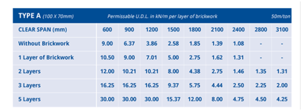
-
Overkill spec on reinforcement- suspended slab, basement wall
Gus Potter replied to Tony C's topic in Foundations
Hope this helps, a bit lengthy but... You maybe can use mesh but if you want to achieve the same equivalent bar area to 12mm diameter H12 bars then you may need to look at the B type structural meshes, perhaps a B785 mesh? The rub here is that the bars are different sizes in each direction with different spacing. Has the slab (maybe basement walls too) been designed as a two way spanning slab. Roughly meaning that all the edges of slab are fully supported all round so that the main reinforcement bars act in two directions perpendicular to each. If so, then you may need four layers of mesh (2 top + 2 bottom) as opposed to your 12mm diameter H12 loose bars top and bottom as the secondary bars in the mesh may be too small. Although mesh can be great you can have a problem with “nesting” if using lots of layers. Were four sheets come together it’s difficult to lap them properly and keep the concrete “cover” to the reinforcement. You can get a flying end mesh but on a small project this can add to the cost, difficulty in sourcing and you may need to detail it up so it fits. Also think about how you reinforce the corners of the basement walls as you can get congestion here too. Although mesh can be appealing if you have congested reinforcement it’s harder to compact the concrete properly and that can cause problems later on. Perhaps have a look again at using loose bars. An H12 is not a bad bar, not too floppy and not too heavy. They come in various stock lengths, easy to source and price match. Also, if you run out you can nip to the stock holder and grab a few more. Any off cuts are great for garden stakes or using as dowels etc. Once you get going with tying loose bars you’ll get along fine I’m sure. If you make a small mistake then all you need to do is remove the odd bar or two rather than sheets of mesh that you may have cut. Just remember that when rebar is tied together it is very heavy so make sure it is properly braced and shuttering is supported. Clay soil (say when you have cut down a tree) can exert a significant load on the walls of a basement. The soil can take a number of years to readjust to the new ground water conditions. There are a good few ways of designing concrete basements / floor slabs. When you don’t have other buildings /sewers etc close by then broadly some key areas considered are; strength (so it does not collapse), deflection (so it does not bend too much and damage other parts of the structure) cracking (to control water ingress and again damage to other components and finishes) and buoyancy / drainage... it’s not a boat so you don’t want it to float if the ground water rises. When a floor slab is say simply supported at each end only and it is loaded from above you will get tension in the bottom of the slab. Steel is good for resisting tension hence your main bottom steel. If you have a load bearing internal wall in the basement then you have a two span beam. You still get tension in the bottom of the slab as you approach the middle of each of the two spans. However, you usually get tension in the top of the slab over the internal wall. Hence your main top steel. It may be that the basement has been designed as a continuous box. In effect the concrete and reinforcement work together at the corners (often called a moment connection) as opposed to say the basement floor and walls acting together with the suspended slab only designed to prevent the basement wall heads moving inwards and to carry the loads from above this is more of what is called a pinned connection. If this is the case then you also have tension in the top of the suspended slab and the outside of the vertical basement wall at and near this junction thus you need some steel in the top and outside of the vertical walls and this can be a congested area. You can ask the Engineer how the design works, often they are more than happy to explain. It’s worthwhile to know how something stands up, especially when you are finished the project and enjoying the fruits of you labour in front of the fire on a windy winters night.

