


Annker
-
Posts
231 -
Joined
-
Last visited
-
Days Won
1
Everything posted by Annker
-
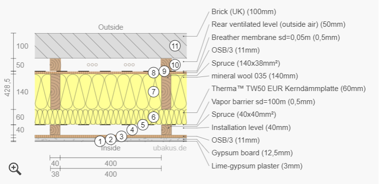
@Iceverge I didn't initially realise that your pdf sample build-up was from an interactive tool and free to use. It's a great bit of software, I don't have German to understand some of the descriptions but thankfully numbers and values are same in both languages! I've played around with the buildup and came up with design that in separate components makes sense to me and I would be very comfortable delivering onsite but I'm not certain it works all together though. The 140mm mineral wool within the studwork makes up the bulk of the insulation, and, vs. PIR, ticks the box for breathable and acoustic performance. Overboarding studwork is 60mm PIR in large format boards tends itself well to be the insulation choice to be fixed uninterrupted over the studwork, and it also deals with cold bridging spots. (Perhaps this will be reduce to 50mm or 40mm thickness) This PIR layer could be tape and may be sufficient to provide a VCL but for the minor additional cost I've chosen to spec a sheet VCL 40mm service cavity internal to the wall construction proper (will likely be formed with 45mm battens) 11mm OSB behind the plasterboard to give a frimer wall finish, especially as I have the studwork @600mm c/c @Iceverge You assigned "Rear ventilated level (outside air)" to the cavity in your model; I have simply copied you in this. How did you know to assign that particular selection to the cavity, its illustrates battens in the model which I don't believe should be there in reality. Insulation_of_TF_1.pdf
-
Any recommendations for a videocamera for site?
Annker replied to CalvinHobbes's topic in Project & Site Management
Another vote for the reolink. A client had one on his project and it was a great piece of kit. I've started my own project now and will buy a reolink myself. That £4p/m sim was a great deal pity its no longer available. Still the O2 sim at £50 p/a ain't too bad I suppose -
Hi Iceverage, ATM my target u-value is TBC. Rightly or wrongly, I had in my head to get the structural arrangement figured out and then size insulation thicknesses/type accordingly to meet the confirmed u-value target. My project is chiefly a renovation of a victorian semi-d with an 2 storey TF extension; the ground floor will be an office and a bedroom will be above on the 1st floor. As such it is a relatively small extension, there are only 4no windows so I can easily design them to opening either inwards or outwards. I have actually flicked over that pdf before, I think you had it attached to a previous comment in another thread. I had discounted its design (omission of vcl) as it added more choice/questions/queries all which lead me away from making a decision. I suffering badly from analysis paralysis, and I will never get the thing built if I continue this way! I note that the internal finish is lime-gypsum plaster. Is that an actual product? Lime makes sense as it provide good breathable characteristics required in that design; in contrast to gypsum so that's a little confusing. Also is there doesn't appear to be a service cavity? Appreciate that there isn't a vcl to protect but I have always liked that the service cavity provides some manner of containment for cabling. You make good points about PIR from an acoustics performance perspective, and that PIR foil faces introduce additional (potentially moisture trapping) layers. I have specific concern about that in my initial design.
-
Yeah I previously used 11mm osb but had read 9mm as being sufficient and commonly used, irrespective of that I probably will still use 11mm as the extra cost of 11mm vs 9mm on a TF of this scale is minimal. Again, on my previously built TF I too kept all insulation within the studding & service cavity, however my research over the past day has pointed toward adding insulation external side of the breathable membrane and osb, commonly termed "cavity wrap" The rationale is that insulation in this position is not interrupted by studwork therefore, continuous and goes some way to reducing cold bridging. It makes sense to me, although there must be a specific wall tie required to tie the TF to the brickwork, I'm yet to look or find it. Why do you use osb internally, certainly it would create a very solid wall but it adds a significant chunk to labour and material cost, are there other benefits? Given the service cavity would internal side of that osb layer it doesn't provide patressing either, at least not in my build-up arrangement.
-
Hi all, I'm at building reg design phase for my planning permission granted victorian refurb and extension. For context I am a carpenter and I have done a couple of stick frames previously but not in the past decade, therefore I would appreciate critique of my preliminary TF design before I sit down with my SE and Architect. From external to internal: 100mm brick external leaf 50mm cavity 25mm-50mm PIR insulation (Thickness selection TBC to achieve yet to be determined target U-value) Breathable membrane 9mm osb sheathing 140mm timber studwork 140mm PIR insulation with studwork VCL 50mm x50mm battens (to provide service cavity) Plasterboard and Skim coat finish Queries: Is a 50mm cavity sufficiently wide? Will placing PIR insulation cold-side of the breathable membrane create a interstitial condensation risk? I have seen the VCL positioned internal side of the service cavity, however I believe the VCL is better positioned external side of the service cavity Any options or thought are appreciated
-
Limited height and ground floor Insulation Dilemma
Annker replied to mickeych's topic in Underfloor Heating
I'm working out a foundation design for similar cellar excavation, and its a struggle to get much detail online. Two tibbits perhaps of interest to you The SE design needs to perform under 2 conditions. First during the construction phase and then during the final condition post-construction. Obviously subject to soil types, structural bearings and the difference between external GFL and internal FFL (existing and proposed). The general rule of thumb allows general cellar excavate (In contrast to "hit and miss" 1 metre sq pits when undermining/underpinning) is to permit ground excavated above a 30deg angle away from the base of foundation, (I recall some sketch suggesting as deep as 45 deg). -
My house has a cellar which I am considering converting to a habitable space. Currently headroom is only ~1.8m, to achieved sufficient headroom and compliant floor build-up I would need to excavate the floor sub-level to ~400mm below the base of exsisting footings. Typically that would mean underpinning the footings however I think there is an alternative method where a concrete ring beam is cast at the base of the footings. This onits the need for underpinning works albeit at the cost of floor space. Is anyone familiar with this method and if so can you point me in the direct of a technical resource outlining the method?
-
How to design a domestic plumbing and heating system
Annker replied to Annker's topic in General Plumbing
Hi Simon, Great that Design Guide sounds exactly like the kind of resource I'm looking for, that's evening reading sorted for the next few weeks! Thanks for the other points also. Did you solely design your system or did you both design and install it as well, and if so did you weld the manifolds up yourself? I guess the key is to pressure test what you install. I think the manifold system also facilitates this as you can isolate testing and potential leak points a little easier -
How to design a domestic plumbing and heating system
Annker replied to Annker's topic in General Plumbing
Hi Tony thanks for the response. The house is 1870's semi, currently no wall insulation. I can't do EWI as it would cover my attractive brickwork and I'm against IWI on solid walls due to the risk of interstitial condensation As such I believe heat pump is may not have the sufficient high temp output for a building fabric with such relatively poor thermal efficiency. Gas fired CH seems to be the best option AFAIK. The plan is the located the plant room in the cellar, and I have some flexibilty which part of the cellar the plant room will be located in, so have scope for a centrally located vertical riser. -
How to design a domestic plumbing and heating system
Annker replied to Annker's topic in General Plumbing
Thanks Jimbo, that's helpful. Keeping the runs <6m isn't so easy in even a moderately sized house, certainly points towards having the plantroom or (manifold at least) centrally located if possible. I've a cellar so that gives me a bit of flexibility on where to locate all that gear on the floor plan. -
How to design a domestic plumbing and heating system
Annker replied to Annker's topic in General Plumbing
Anyone at all able to chip in with any kind of advice on my post above? -
How to design a domestic plumbing and heating system
Annker replied to Annker's topic in General Plumbing
Just to add further description of the property: Semi detached Victorian Floor area ~216 m sq /2325 ft sq. Laid out on Cellar, Ground and First floor 4 ensuite bathrooms (no main bathroom) 1 cloakroom wc -
I am starting a large victorian renovation and it will involve, (amongst everything else) installation of an entirely new heating and plumbing system. Plumbing, like most trades, seems to have two main aspects; design and installation. The installation part on my last two projects was painful. The plumbers seemed happy to work to a wider tolerance that I'd deem acceptable. I had to repeatedly check and correct the setting out of 1st fix & associated ware positions. I seemed to spend much time overseeing a supposid specialist trade and in frustration I frequently said to myself I could do this myself! Clearly I wouldn't have the knowledge or speed of an experienced plumber, but being a carpenter by trade and therefore well experienced "on the tools" I believe I'd have the dexterity to install a large amount of plumbing/heating system. Perhaps then enlist a plumber on a day rate for soldering, final connections, etc. Currently I don't have the knowledge to design the system. I see a lot of commentor's on this sub-forum design their own systems. Perhaps it's something I could design if there was a suitable "design your own" resource. From reading various threads here I have a basic idea of some very general specifics for the system but clearly this is far from a working design: The house is Victorian with solid brick external walls. I won't install EWI, neither IWI due to the risk of interstitial condensation so I'm not chasing thermal efficiency with the refurbishment works. In such situation I understand that a gas fired CH system with radiators to be the most suitable Pipework in Hep20 or similar to facilitate a simpler install All F&R to radiators on individual loops from a manifold Domestic feeds similarly from a manifold My rear facing roof surfaces are perfectly orientated to capture sun rays so I would like to instal solar panels although I have no idea how these will be integrated into the MEP system I believe the house will be far from airtight so no MVHR but I've worked on large scale projects where the MEP system is designed by specialist MEP consulting engineers but does anyone know if there are smaller MEP engineers that design the plumbing & heating system for domestic projects and if this is a common procurement route for a self-builder? Has anyone had a design drawn up this way? Maybe someone can recommend an designer.
-
Yes correct. When I twist the stopcock key fully down there is still water running from the tap, similarly when I flush the toilet I can see the meter running which also indicates the stopcock is not fully shutdown. I believe this could be that the gate in the stopcock doesn't fully shut. It is probably not enough of a flow to completely prevent me making on the new MDPE connection, but as you well know these "5 minute jobs" always take an hour and then by that time I'm up to my elbows in water🤿
-
@saveasteadingI am not sure if you or I understand the other correctly, I don't believe there is a leak currently. I have only just bought the house so I'm not entirely sure if the current flow/pressure is sufficient other than it isn't particularly strong; however given the current plumbing systems age, likely its not configured efficiently and therefore producing low pressure at the tap. @TonyTYeah, I will do this. I have a pressure gauge attachment so those too metrics would be useful. I will have to do a bit of rooting to find a outlet directly on the main pressure to get a correct reading.
-
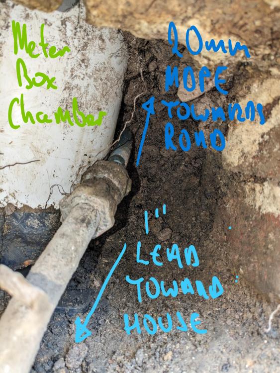
I'm at the beginning of a big renovation project. One of my first tasks is to prepare a carpark for the arrival of tradesmen so I'm getting affected buried services upgraded now, save reopening ground down the line. Existing water supply pipe is 1" lead which I am going to replace with MDPE. South East Water have confirmed I can work on customers side of the meter and even better once the job is complete I can send on the associated invoices incurred, to which they will credit back to my SE Water account to the value of £250. I think that's reasonable offer myself! I have excavated customer side of the meter box chamber and it appears that the supply from the meter is 20mm MDPE which is then compression fitted on to the 1" lead. As in the photo below its not obvious how the MDPE supply connects to the meter as it appears that the 20mm MDPE pass by the box chamber and out towards the road. All I can think is that the MDPE loops back on itself and connects to the underside of the meter. I'm not sure if that arrangement is possible, it seems torturous but seemingly it must take that kind of route. Just to note that the meter is not bypassed; flush the toilet and the meter records it. Is 20mm MDPE supply from the meter sufficient for a large 4 bed property (4 ensuites, downstair loo, and all the other standard requirements)? Before I had unearthed the 20mm I had it in my head that I would replace the 1" lead with 32mm MDPE, however if the supply immediately exiting the meter is only 20mm surely that will limit the flow gains a 32mm diameter pipe would offer? I also note that the mains stopcock in the meter box chamber doesn't completely shut off the supply. I wonder if I could raised that as an issue with SE water and then perhaps they would kindly replace the stopcock and as the path is open allow me to remove the couple of foot of 20mm allowing me to connect a new 32mm MDPE to the meter?
-
Recommendation/support for build system
Annker replied to matt58k's topic in Insulated Concrete Formwork (ICF)
Thats a good idea, and one that I never thought of myself for some reason. Have you experienced many building supply companies refuse credit card payment? -
Hello all, not entirely sure which sub-forum to post this in, many questions to answer but I thought this neck of the forum may be best! I have recently bought a large victorian semi-d in need of significant renovation work. I bought the house with ~60% LTV mortgage and the initial plan was to renovate the property to continue its life as a single dwelling house.However since purchasing my conversations with colleagues, estate agents and my own ongoing assessments of the property (I work in construction) is directing me to consider the potential of converting the property into 2x (potentially 3x) self contained 3 bed flats. For context I have extensive construction work experience in both new build and renovation works in both small scale and large scale development, however I have not much experience in, say the administration, of such a residential conversation project. I imagine the first steps are to put together a basic appraisal of the project and therefore I'm trying to list the big ticket items that will determine if this scheme is feasible: How will my current residential mortgage lender (HSBC) view my plans. I have called the broker who arranged my mortgage and he is going to make enquiries with my lender to ask if they would allow the scheme. He said its likely I'll have to refinance. That cost allone may put a stop to the scheme Determining the likelihood of obtaining Planning Permission for the scheme I am fairly confident that PP would be granted as the attached neighbouring property as converted to flats as is the property on the other side. Determine if there Is a market for converted flats I had a brief conversation with the EA we purchased the property from and he said he has a few investors who are looking to buy such a scheme in its entirety so there are buyers in the market at least Financial appraisal. Even if the conditions above are met obviously the numbers still need to stack. I believe I can cost a regular renovation quite accurately however with little experience of flat conversions I'm trying to think of the big expenses that are particular to this type of project: Splitting the existing single household utility supplies to serve 2x or 3x self contained units, I imagine this will be a costly but for the scheme it would be necessary expense Fire safety/regulations Acoustic performance/regulations Anyway I would greatly appreciate if any group members can advise on any of the items above, give my pointers, additional items to add to the list, or indeed any offer their experience if they have undertaken a similar scheme: Thanks for reading!
-
Plasterboarding and Finishing recommendations
Annker replied to revelation's topic in Plastering & Rendering
True Nick. In anticipation of this, at plastering stage I mark out down/up light positions so the plasterer is well aware his finish will be literally under the spotlight at those locations. But I have to disagree with you regarding the acceptable standard. A plastered finish should be a near perfect finish, it really shouldn't require any filling & sanding. The general commercial procedure on large residential projects is that a sum is retained from the plastering/drylining package until the mist coat has been applied and the plastering/drylining contractor has QC's their finish. Once the finish is accepted the retained sum is released. It is generally agreed that any surface repair up to the size of a 2 pence piece is included the the painters making good allowance; but scrim tape/beads showing through the surface etc would be the responsibility of the Dryliner to refill over. -
How about making up the 175mm with further insulation? I imagine you'd need to check if dimensional compression would be an issue at that thickness, but certainly would be cost effective labour wise.
-
replace floor/ceiling joists -am I insane?
Annker replied to Crowbar hero's topic in General Structural Issues
One concern I'd have is that removal of the existing joist deck could take away any lateral restraint they are providing the wall on which they bear. In my situation I want to raise the floor levels of some rooms above ~340mm above their existing level. So the procedure I would use would be to firstly install/fix the replacement joist deck prior to removal of the existing joist deck. I believe you will be reinstalling the new floor at the same level as the existing, therefore you wouldn't be able to do that, but I think you should think about installing some manner of temporary shoring bracing until the new joist desk can provide it. -
replace floor/ceiling joists -am I insane?
Annker replied to Crowbar hero's topic in General Structural Issues
Hi Crowbar, did yo go ahead with replacing all the joists? I have an upcoming project where I am considering doing the same. -
I believe merchants are going to have a think long and hard about any price increases in 2023. Demand from both domestic and commercial builders will be a fraction of the levels of recent years. Any material buyer in '23 will certainly find good value if they look for it.
-
Hello all, I hope to have a fairly big renovation/extension project coming up next year (currently negotiating a house purchase). I work in construction and think that Site logistic are always one of the more challenging and stressful hurdles to overcome on a project. I will be doing a lot of the work myself and I'm considering buying a caged tipper truck for the project. I would like to know if any other self builder has bough one for their own project? Site access is not the best as the property entrance is on a relatively busy road. There is driveway parking for say 3 or 4 cars however there is no road parking outstand the house. Concrete deliveries, skips etc are going to cause unavoidable traffic headaches but I thought if I had a tipper I could at least reduced these. There are numerous building material yards near the property and having the tipper would provide great availably to pick up materials in required qualities as and when required and drive straight onsite with them. Also I think a caged tipper could be a good alternative to a skip for waste disposal. I understand a waste disposal transport license is required but again, it would offer great flexibility and remove the stress of getting skip wagons on/off site. If there was road side parking available I think the caged tipper would provide an even use. Not alone would it replace the need of a skip but also eliminate the hassle of obtaining a skip license. Anyway would really appreciate to hear you opinion on above and indeed if you encountered challenging site logistics how you overcame them.
-
For the sake of a few extra lengths of metal I'd recommend to go 400 c/c with regardless of using 12.5mm or 15mm pb. Hangers for the main support channel (used to support tophat sections) are at 1200 c/c and FYI the spec states that 1st hanger can be positioned at 1200 c/c (i.e. no hanger is required at the start adjacent to the wall) however I always used to put a hanger at the start despite a friend's advice (who was professional fixer) insisting it was not necessary! Another useful tip for any MF work is when connecting two metal components together that a much more robust connection is made if screws are driven from the lighter gauge metal into the heavier gauge metal, if that makes sense. For example, with the MF system this means that screws are driven into the lighter gauge hangers to the heavier gauge main support channel and not visa verse.


