JFDIY
-
Posts
498 -
Joined
-
Last visited
-
Days Won
1
Everything posted by JFDIY
-
Some questions on MVHR installation
JFDIY replied to bluebirdnick's topic in Mechanical Ventilation with Heat Recovery (MVHR)
I went and cherry picked components from a few places based on quality, cost or location (I.e. I could collect in person) One thing I made extra effort to source was 150mm insulated ducting, I used the ubbink foam ducts as it looked easy to engineer the routes I wanted and no need to insulate separately after installation, can dismantle them for easy cleaning now installed as well. There's some pics in this thread. https://forum.buildhub.org.uk/topic/11747-silencer-can-it-be-mounted-horizontally/page/2/?tab=comments#comment-208334 Also made a few of my own vertical terminals for about £3 each, but mostly because I couldn't get exactly what I wanted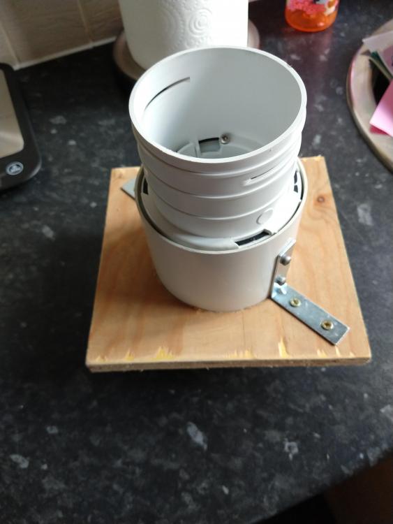
-
MVHR airflow reversed
JFDIY replied to OllyH's topic in Mechanical Ventilation with Heat Recovery (MVHR)
@OllyH did you get anywhere on sorting this or has lockdown got in the way? -
I use the lower style in @Onoff post, to fit a temporary staircase on my own, not recommended, but will breeze a 40kg board at your 2m height.
-
Some questions on MVHR installation
JFDIY replied to bluebirdnick's topic in Mechanical Ventilation with Heat Recovery (MVHR)
You use an anemometer and funnel to read the actual flow. There are a couple in the tool loan pool on this forum, but both now have a bit if a queue for them. I was going to use a road cone and cheap anemometer (£30 on eBay/Amazon), but a proper kit (Testo 417 + funnels) came available and I bought that. -
Some questions on MVHR installation
JFDIY replied to bluebirdnick's topic in Mechanical Ventilation with Heat Recovery (MVHR)
Think I would phone them up and talk to them, I keep getting emails from them saying they are open for business. Have you sent them plans and asked for a full design. If memory serves thay may be a fee (circa £100) to do a full plan which is then refundable against your future order. There are loads of on here that have DIY'd an MVHR design/install and I found you have try and resolve each issue one by one. Just a couple of things I looked into from your post. I wouldn't worry about the room valves for now, get the pipework and room plenums sorted out first. The premium plenums seem to have mounting points built in, the others you will have to hold in place with strapping band or fashion some mounts to retain them. For the one you don't have access to then you could fix the outlet grill to the plenum then fix the grill to the ceiling. I have a similar situation, but I used 100mm Flexi pipe for a couple of meters (as per basic individual fan set up) , then connected to the 75mm radial duct, I don't have a restricted terminal vent either so used a restrictor in the manifold to balance flow. The Flexi silencers are regularly used to save on bends and ducting to/from manifolds. If you want rigid silencers then you'll have to use bends and ducts to suit, can't comment on what is best from a noise attenuation point of view. Oh and if the unit is in the cold lift, all the pipes need to be lagged, others have built an insulated enclosure around the whole unit to prevent condensation. -
Modern Agricultural Barn conversion. Anybody done one?
JFDIY replied to Roger440's topic in Barn Conversions
That Norfolk one is crying out for you to leave the workshop as is and build the dwelling under the lean-to area -
There are some downdraft extractors that can be piped to the outside through the floor, but in doing so you might create a U bend for water to lie in unless you shield the outside from water ingress.
-
@nod How does the complainant know that the workers don't all live together?
-
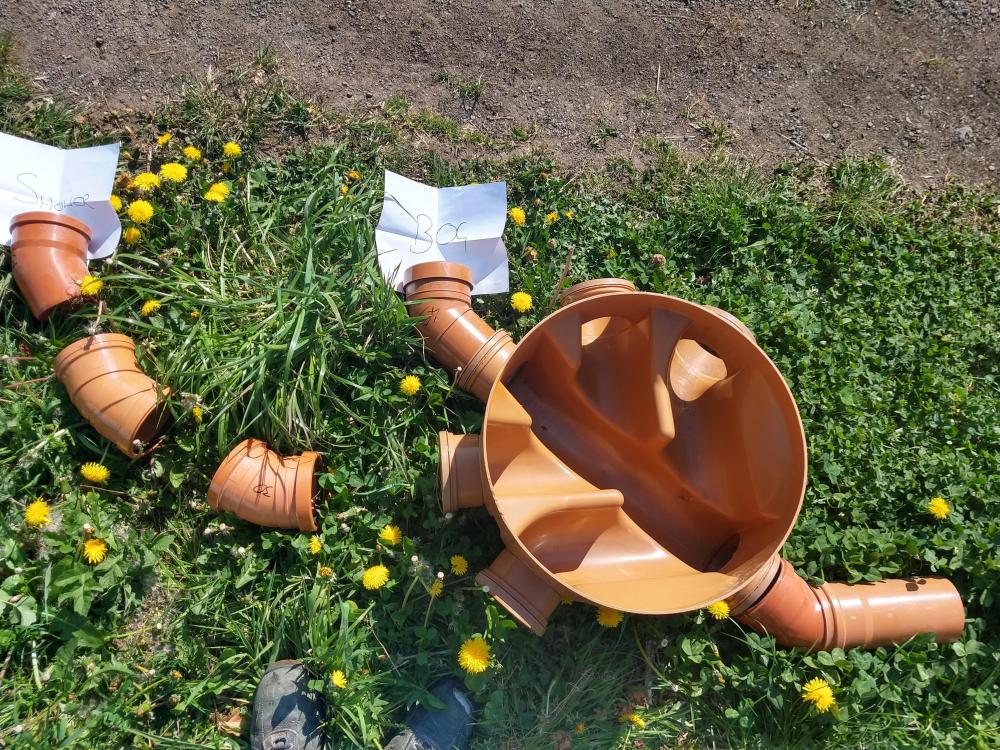
The only reason I looked into it was that we had a sewer run with a 2" drop between my connection and the outgoing main, it kept blocking further up on my side as the fall was marginal. I was able to swap to a level invert I/C and the extra bit of fall has ment that four years on we've not had any re-occurrance of any blockages.
-
Do you have a layout plan? If you want smaller chambers osma/wavin do a verity of level invert ones that you won't find anywhere else.
-
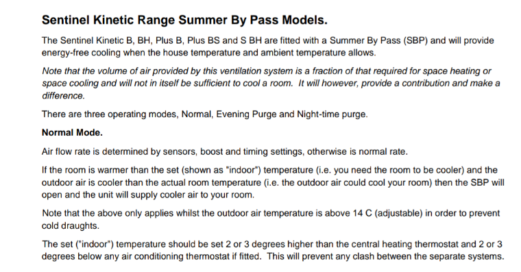
@JamesP Bypass only opened when extract air is above the 'indoor temp' set-point, as far as I know it doesn't relate to outside temperature. Other than if the outside is too cold (based on your 'outdoor temp' set-point) Hope this extract from manual helps.
-
Forgot about the piggary, but that could use another branch entirely again with a 45 straight from chamber again to make it rod-able, two pipes (piggary + shower) then run parallel for a short section.
-
@AnonymousBoschHere's how I'd do it. Single socket 45's straight into chamber on exit and toilet make it rod-able. Swept bend or several 30's make shower rod-able too. Toilet has main run so solids won't get stuck.
-
Stainless steel rail would work, or as you say brass or copper. I'd also consider electric, if you had it on a programmable thermostat it could be only on when you needed it for a few hours at a time, switched off by room temperature or timed. I fitted one of these Elements (link) I grossly oversized it for the towel rail as it is thermostatically controlled, so cuts off once your set point is achieved. Mine is on a timer and remembers the temperature set point even if power is disrupted. Think we're looking at 20p per day for 5hrs time when on, though mine is on central heating as well so it will be lower.
-
You can't 'feel' negative pressure/flow as easily as the supply. Are you feeling it at the port on the MVHR unit or at the end of a duct run? Once you cover an extract duct the flow drops to zero and it certainly doesn't feel as though anything us happening compared to an inlet where there is a rush if air pushing behind it. There are also separate settings for the extract compared to inlet, so you may get have to check the values also are at 30% and 50% as a starting point to match inlets.
-
I don't see the need for the rodding point. I would put a 45 bend on each side of the main run so that manhole is serving the toilet without the solids having to change direction. The chamber is rotated 45 clockwise as per your photo. Then use the other branch and several 30 degree bends or a swept bend to pick up the shower. All should be rod-able from the chamber that way.
-
Could you sheet off the area with clear plastic, both sides and floor seal off entirely. then cut a slit for access with a garden hoe or similar , then dislodge it and see if anything comes out, leave it for a few days then wrap up and remove from roof. I'd do all this with as much skin covered as possible.
-
I've got about 140mm to make up in insulation between my sub floor and screed/UFH. My question is are there any benefits from an ease installation perspective to doing this in two layers V's one thick layer?
-
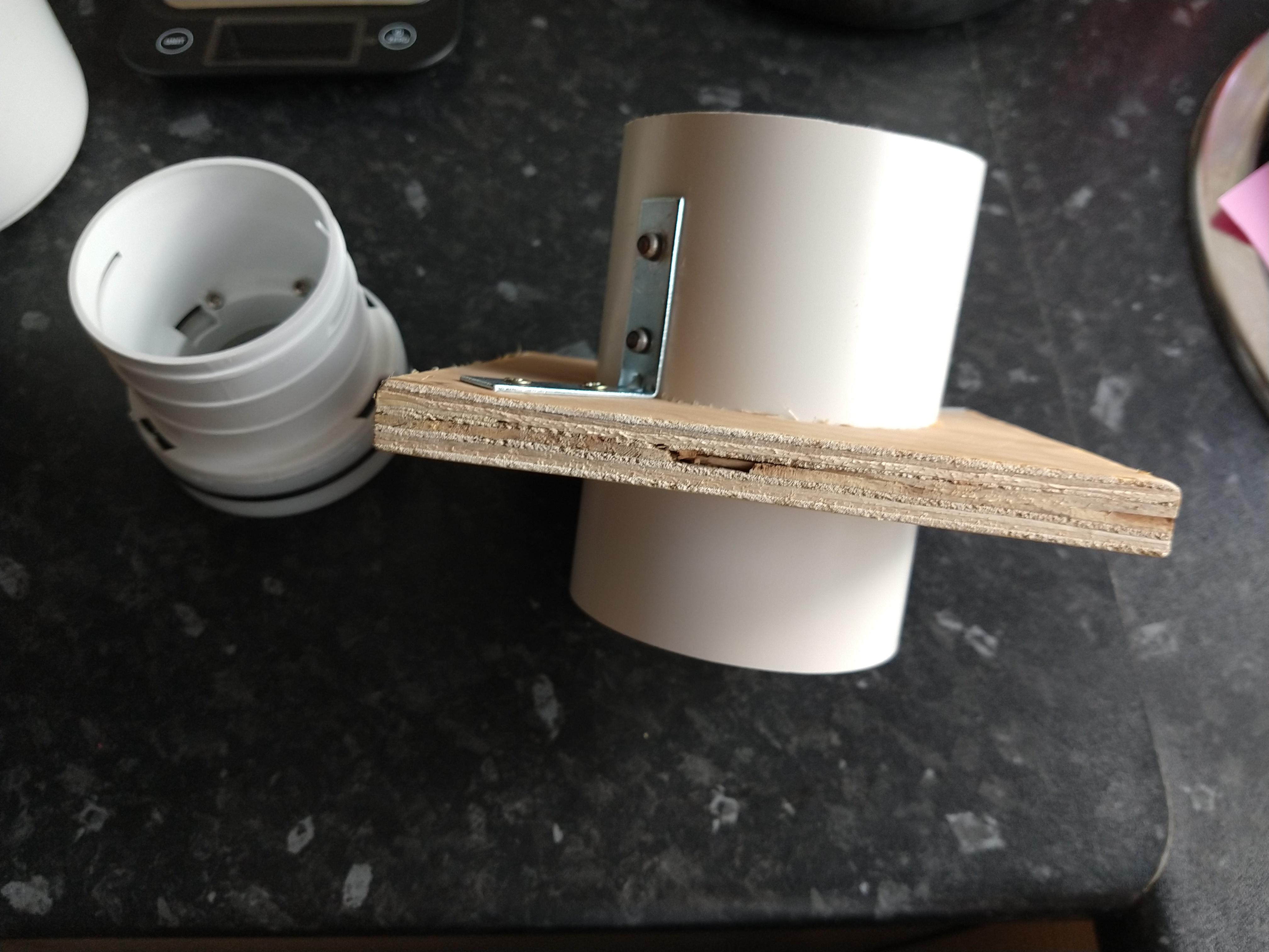
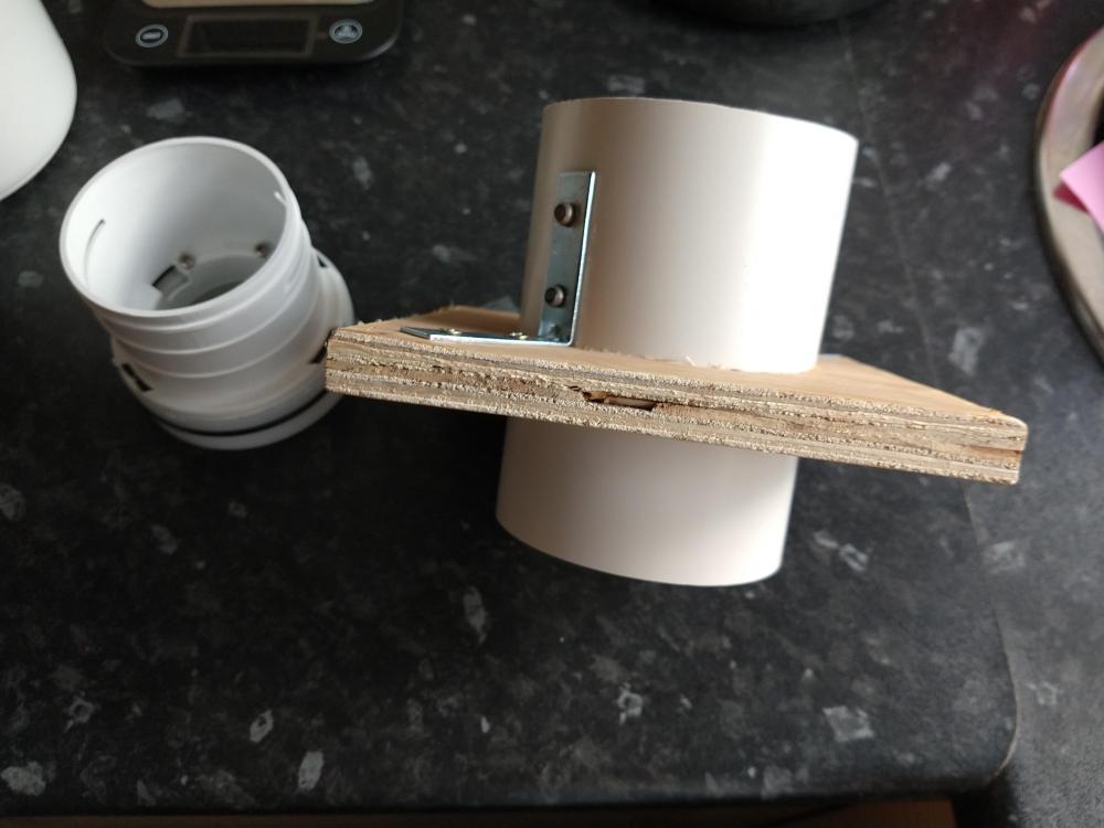
Think 1960's/1970’s car repairs, Ali plate and pop rivets?
-
The % refer to inlet or extract fan speeds in each of the modes: Low Normal Boost Purge. You can set them to certain figures, the instructions show limitations relative to other modes.i.e normal settings must be below boost figures etc. You can also make it switch to those settings based on time i.e I have mine switch to low mode between 9.30pm and 6am so it's silent. I'll be honest the manual does tell you a lot of info. There is also a user manual which might help kinetic plus B.pdf
-
There are two temps on the summer bypass, first is at which internal house temp (measured on extract port of unit) opens the bypass. Second is the outside temp (I think measured at unit inlet) at which the bypass is inhibited to prevent cold draughts. So it might be opened at say an internal temperature above 26c (and presumably closed when colder than this). but will be inhibited from opening when colder than 12c outside as a quick example.
-
So in cooling mode is the direction of water flow reversed? So the cool side of manifold is still the same and vice versa? Otherwise won't the actuator sense the temperature differential back to front so to speak and then just open the actuator fully in the hunt to achieve the 4degrees but never get it and in effect just be wide open
-
Looks like you'll get a few years from that. Thereused to be someone in eBay doing new decks for Westwood's. Might have stopped advertising in the short term. I'd try and get new blades if you can, made a massive difference to my folks old mower, they were about half as thick as they should be, lost about 1/2" off the cutting edge and had lost the wings that create the draught to blow the clippings into the collector duct. It was not picking up properly before, now it's almost as good as new.
-
There's something about 0.3l/s per M2 of floor area in part F which equates to something like 1.08m3 per m2 of total internal floor area if memory serves as a minimum. Even this is considered to be too high on here, but will depend upon occupancy and use. You should aim to demonstrate this for building control purposes
-
If you're (air) pressure testing the system; if using the ones with the nicks you could give them a try, if not pressure testing I wouldn't bother unless properly stuck. You could leak test with two pieces of pipe a blank end and a straight coupler. Stand vertical and fill with water with say 1m of water above the joint and check for leaks.