


TerryE
-
Posts
3822 -
Joined
-
Last visited
-
Days Won
30
Everything posted by TerryE
-
See How Apple and Amazon Security Flaws Led to My Epic Hacking for a salutary case of where this can all go dreadfully wrong. Use cloud services by all means, but I strongly recommend that you keep a local copy of everything on your laptop or PC and back this up to a physical HDD. preferably LAN/ Wifi attached in some out of the way cupboard / garage. That way you guard against loosing everything in the case of theft, fire or a single device failure.
-
Nick something just doesn't square with what you are saying. The M/F sleeve on a 110mm fitting is about 4 cm deep. 2½° over this distance is over 1½mm out of line. The polypipe fittings just don't have that amount of play in them. The forced 2½° is going to put a huge amount of strain on the joints, and will tend to cause failure at the weakest one. At least Jeremy's 2½° banana trick is using the know plastic characteristics of PVCu in a way that will be memorised without building failure strains. Need to think about this further.
-
On our our wastes, I've been using a 135° into a 135° spigot bend and this produces a slow 90°, but this is just too slow for 110mm pipe. The smallest fix offset is 12½° and this is a spigot fitting so I need a female to go into it. Might work in some places. but the geometry doesn't work in my cases I've looked at these bends including the 0-90° version but I just don't like the risk of these for near horizontal runs. Funnily enough your mentioning this. I did the same trick 25 years ago when I plumbed the farmhouse, but I forgot about this issue on this house until I hit it again. It's an option to try. I just wish at least one supplier did true 90° bends. I do get some hits but I suspect that this is just a loose description for 92½° ones.
-
We've got a couple of Gerberits where the soil pipe comes parallel to the wall, does a 90° bend and runs a metre or so along to the stack. To minimise boxing in, I would like the pipe to run parallel to the wall, but the Gerberit frame fitting fixes the socket square to the frame and if I loose the extra 2½° along the other wall, this pulls the pipe bend out about 5cm. Grrrrgghh!! Does anyone know who does a true slow 90° bend in 110 PVCu? Alternatively what is the trick to get around this issue?
-
Ah, but it got you doing a detailed rebuttal, didn't it? Thanks for instructions on how to do it correctly. At least this means I can smile smugly at Jan, because I told her (i) you cant' safely use Hep2O pipe in a copper compression fitting and (ii) Hep2O pipe won't take the bend anyway. Her argument was: "that's what the guy did". So now you've got the casting vote.
-
Thanks Nick. What you recommend is what I meant on my option 3. The cranked unions were the second. I quite like option 1, but I was concerned about the risk of the situation that Crofter described. I suspect we'll go with your method. There are a couple of good YouTube tutorials on using these. So when are you going to start your YouTube channel?
-
I had a look through those videos. Ignoring the wonderful US centifeet units, it was useful 101 stuff if you haven't done this before. The Excel spreadsheet is fairly straight forward as the most complex bit is adding / subtracting one column from another. The thing that I would re-emphasise is: don't assume that your Dumpy is properly calibrated: check! So: Having exactly centred the levelling bubble at one orientation, it should remain exactly centred as you turn your level through 4×90° allowing the bubble to settle each time. Set up two reference points at a minimum of 40m apart. Setup your level next to one and use the precision side of your staff to get the relative heights as close to nearest mm as you can. Now move your dumpy to the other end and repeat. If the two measurements are more than a few mm out then your optic level is out from the swivel plane. If either of these are off, then your manual will explain how to recalibrate the level. Any surveying that you do can only be as accurate as the calibration of your Dumpy.
-
There seems to be three variants for fitting. All present a pair of ¾" BSP males at a horizontal 150mm separation: The bar mounting as described by Peter and OnOff. This has 2×15mm female pipe compression fittings to accept the input 15mm compatible feeds behind the plasterboard and tiling. 2×½" to ¾" BSP males at an offest. These take 2×½" BSP females at horizontal 150mm separation 2×inline 15mm compression female to ¾" BSP male which take 2×15mm pipe ends clearing the tile and again at a horizontal 150mm separation. As I see it in all three cases there are two key issues: the fitting or pipe must be fixed firmly at as a set set depth with perhaps 4mm tolerance otherwise either the covers won't screw down fully or there will be insufficient exposed thread to clamp the shower bar down firmly. So you really need to know what type of tile and fixing profile you are going to use before you do the plaster boarding. You plaster board before you have the opportunity to pressure test. My current thinking is that we board the wet surfaces in green plasterboard and don't skim these, so we seal and fix the tiles directly. Given this isn't it just a lot easer to construct a panel around whatever noggin position and leave this panel open when boarding out and plastering? This was we can wait until after the plasters have left site before making up the noggin and pressure testing before removing the screwing the noggin into its place; replacing and sealing the green access panel and then tiling and finally refitting the shower mixer bar when convenient. Nick, you must do this all the time. What is your preferred approach?
-
The Great Thermal Mass Myth................
TerryE replied to Jeremy Harris's topic in Boffin's Corner
Yes but his rampump is amazing- 122 replies
-
- 1
-

-
- thermal mass
- heat capacity
- (and 4 more)
-
We are the same as you but we aren't using timber lintels. They're standard hidden steel ones as they only need to carry the weight of the stone skin.. Yes, we have a dummy Oak lintels, but these are cosmetic only and just green oak (which we will need to repoint in a year because they will shrink.) We have a 300 year-old stone farmhouse next to our new build and I did the same trick over 25 years ago when I had to replace some rotten lintels and move a couple of doors and windows -- only here we used reinforced concrete lintels. PS. I am a little concerned about your comment "deep enough". Our windows are attached into the frame and boxed out to site 45mm out in front of the Panelvent almost closing the 50mm gap. (The wooden frame and the stone skin have different expansion and humidity characteristics so they shouldn't be directly coupled. The windows sit behind the stone skin, with a slip surface between the frame and the stone skin.) In our case the dummy lintels actually sit about 45mm below the top of the window frame partially covering the frame. The stone is only a nominal 125mm thick (it's a planning requirement that we use the local rough cut stone.) So the lintel only carries this outer skin, which is non-loadbearing as far as the house is concened.
-
We have an MBC slab and our site had a greater slope than yours. I think we ended up taking over 20 × 20 tonner loads of earth and subsoil out of what is a fairly small plot. The issue in our case was ridge heights and as the site had been a farmhouse vegetable garden and part of the yard, there was a lot of soil and made-up ground added over the last 150 years or so. We took the slab down to a level firm clay base (known as Oadby Member) and laid the crushed stone for the slab on this. But key to all of the was our Geotech survey. Our cost ~£2K which might seem steep, but we and MBC really needed to understand the subsurface build up, and they took 4 core sample roughly at the corners of the build and went down to 6m. I doubt whether the slab company's structural engineer will sign off the slab design without this, and if they are willing to then I'd be very suspicious. Also remember that you'll need to take the level base at least 1m out from the slab perimeter and almost certainly install a land drain around this perimeter to keep the water levels uniform across the site. PS. Looking at your original diagram, I don't thing that this approach is correct. The timber frame sits directly on the slab, so If the slab top is below the high level then you will end up needing a small retaining wall set back at some 1m from the external wall of the house. If the slab top is above the low level then you will need to face the slab insulation on that side. Of course you might end up doing a bit of both. But I would think that you want to keep at least half a metre of ground around your slab at a single ground level. PPS. Also see Soil stack to 110 drain -- the wrong way and right way for setting out your drains.
-
BTW, the site that this guys is using is earth :: a global map of wind, weather, and ocean conditions. How to configure it is at around 2:40 into the talk. It's really worth a look at this site!
-
My house is going green - mould on inside blockwork
TerryE replied to readiescards's topic in Brick & Block
Life. If there is an untapped ecological niche and a suitable organism, then it will exploit the opportunity. In this case the build is just very wet, so this type of algal growth can get a hold as well as types of fungus. However unlike Ian I wouldn't be so relaxed about this. I'd want to get the build weatherproof and dried out as soon as practical. -
Ferdinand, you are right to point out that this might be driven by the strong El Ninos so this may have happened in the past but that we didn't have the contemporary data. But note his discussion of the QBO at around 13:00 in. This had maybe 15 or so cycles, which meant that this dataset went back 30 years and there wasn't the same sort of dive from max to min in less than 6 months before which supports his assertion that this is very unusual. Yes the lecture had a polemic element, but all the guy is trying to do is to flag up that we should have a better understanding of what it going on here and that there might be a global impact on our food production. Yes, if we look back in the historic record we've had some huge failures in the past, for example Krakatoa cause two years of crop failures and many millions starved globally as a result. Surely the response to such calls should be measured impact assessment by governments and their scientific advisors. The hate responses that the guy got for putting this online were truly depressing. Climate denial seems to have become a religion rather than an evidence informed debate about the data, cause and effects.
-
Nick, thanks for the link and how depressing! But take heart: Mr Trump doesn't believe in Climate Change so we are all really experiencing mass delusion
-
That's not counting the Bette Bath!
-
Bollocks
-
Soil stack to 110 drain -- the wrong way and right way
TerryE replied to TerryE's topic in Waste & Sewerage
Thanks Nick. As you said you only get one shot and whilst the solvent working time is ample for a 50mm pipe or smaller, this is a 110mm joint in an awkward position. Normally, if the odd joint goes wrong then you say shit and at worst you might need to cut the pipe to use an inline double socket to rotate it or whatever. For this one joint, it would be a case of having to core down through 75 mm of concrete and rebar as you first suggested -- at a minimum. On reflection I think that I'll go with a pushfit. As long as the riser is cut nice and square and finished properly there shouldn't be any issues. -
Soil stack to 110 drain -- the wrong way and right way
TerryE replied to TerryE's topic in Waste & Sewerage
@Barney12 the coupler that you mention wont give me the depth to include a branch @warby I am using one of these on the first floor for the two toilets but I only need a single branch on the ground floor. @NickfromwalesNick, if I have 2½° fall-away from my pan that about 5cm so the branch centre should be around as far as I can see the pipe centre at the branch needs to be around 12cm above FFL or 13½cm above the slab. However I have a Gerberit with wall hung pan so I can play around with the connection height a little as well as the gradient, so I could get away with around 15½cm or so. That's enough to fit a D/SW Single Branch such as the one below, which requires 152mm. OK I still need an expansion gap on the pipe but I 've got a rodding access immediately above this which I could make push fit at the top or I could use the converter kits which convert a solder fit socket to a push fit one. As Jeremy points out I will need to be anal about getting the cut accurately square which is going to pain in the arse given the position of the pipe but I can make a jig and use a tenon saw and finish off with the old woodworkers trick with a sharpie. And this is still dependent on being able to solder the PVC-U 110 drain to a PVC-U 110 stack branch. Anyway having done a bit of cut and paste from the OSMA catalogue this is what I am looking at (C=152mm):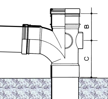
-
Soil stack to 110 drain -- the wrong way and right way
TerryE replied to TerryE's topic in Waste & Sewerage
@Nickfromwales About 30cm @RandAbuild Finishing off a single WC is easy because there are standard F/M fittings for this. Our problem is that this stack as well as the G/F toilet+basin also goes into the bathroom and takes another 2 toilets, 2 basins, a shower and a bath. As Nick says, we really need a smooth straight-bore connection from the internal 110 to the bit sticking out of the slab. A cement femail / pushfit double connector would be fine apart from fitting in the branch to this toilet on this stack. -
Soil stack to 110 drain -- the wrong way and right way
TerryE replied to TerryE's topic in Waste & Sewerage
At least we got this advice now And for the benefit of others who might end up going down this shit hole, so correct method is: Or if your slow bend is lower add a short section of pipe which has a female socket at slab level or a straight pipe section with a double socket again aligned to slab level. Fill with a blanking cap whilst the slab-work is going on. And if I recall Dave actually had his cap about 1cm below the slab level so making power floating easier, and he then tapped this 1cm out after the slab had gone off. And now back to my cock-up and how we mitigate this. A few clarifications: When you say a double socket straight connector, are you meaning double push-fit (p/f) or would you use p/f+solder fit using PVC-U solder for the lower socket which is going to be resealed in the concrete? My inclination would be to use the latter rather than p/f upwards against the flow direction. That assumes that we've done the test on a piece fo soil pipe to make sure that the solder socket and the pipe are solder compatible. We have two soil pipes and only one has a ground floor toilet branch attached. The other has rodding access and a lower spigot to the utility sink waste. Surely if solder fit is compatible then can't I just position the double socket above the slab? Lastly if you are suggesting using a double p/f, then why not just use a triple socket branch direct onto the soil pipe and solder the bottom socket? We can use solder to expansion converter for the top socket to give the required expansion. It's just that doing the 6" core is going to be costly and risky -- if anything goes wrong then what is plan B? So if I can avoid this, I will.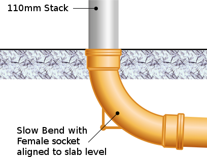
-
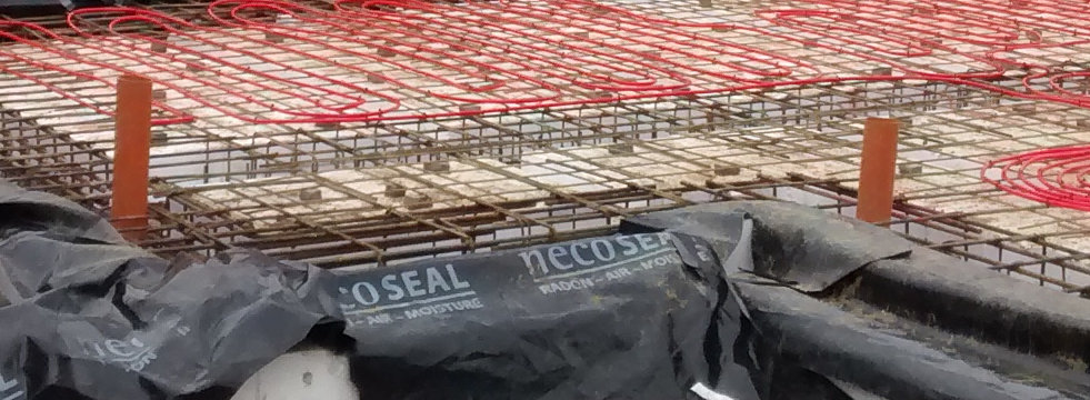
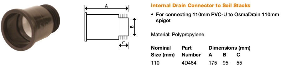
All of the underground fittings seem to show the underground 110mm terminating in a 110 push-fit female connector at ground level and you simply slot the bottom section of your soil stack into this. OK, I should have thought this one through when we did the slab but I didn't. What we did was to just use a piece of the straight generic 110 pipe that the slab crew provided which now comes out of the floor and which the guys seemed to view as standard practice. Our intent was and is to trim these to at or near slab level after the pour. See photo below. Osma do a female 110 push fit to male rubber sleeved insert as below, but the issue that we have is that our toilet connector from our toilet joins the stack at ~145mm above slab level so this is too tight. Can anyone recommend a lower profile M/F soil-underground connector or alternative approach? This can't be an uncommon problem. I really don't want to start to chip out concrete to recess one of these
-
An old gas fitter showed me how he did it about 20 years ago. The then BGas rules were that you weren't allowed to use flux when doing end-feed joints. I guess the logic was that unlike wet work, any residual solder in the pipes wouldn't be flushed and therefore slowly corrode the pipe internals and if carried into the appliance that as well. He burnish his pipes till they were oxide free and brilliant, then tinned the pipe and burnished both the fitting and the pipe again, before soldering with a flux-free solder. My hit rate using a flux-free solder is a lot worse than with, so I would prefer the options of flushing the assemble piece with water then air to remove any internal flux. Of course you'd need to let the pipe fully dry before doing a manometer test.
-
Barbey, when are you putting your windows in? Compriband is a special expansion tape. It would normally be used by your window installers as part of installation if you have a stone or brick skin which is in-place before the windows are installed. In our case our windows are installed in the MBC frame and the skin is added later. In this scenario, they can't use Compriband as it is gap filling mechanism, and there is no gap in front of the windows, just the wide outdoors.
-
Dave, in many ways using copper is actually easier because the installation within the building fabric is robust and rigid. I've done gas plumbing before, but that was in the days before you had to go on a long course and get a certificate to prove that you understand that you can't use flux and have to pressure test everything as part of commissioning. I've still got the clear plastic tube to use as a manometer, but it would some new red wine to colour the water. Our primary hob is induction, and as Jan says these two rings are purely backup so that we aren't totally stuffed in a power cut, so we'll probably keep it simple and use a single bottle.