


TerryE
-
Posts
3823 -
Joined
-
Last visited
-
Days Won
30
9 Followers


Recent Profile Visitors
19567 profile views


TerryE's Achievements
Advanced Member (5/5)
1.4k
Reputation
-
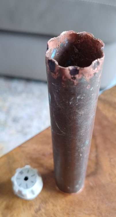
It's a std square spigot that you see on older taps and stopcock butterflies. I've packed up for the night, so can't be bothered to get out my micrometer to measure it. As I posted on the referenced topic, I made up a little tool (that sits tightly over the knurled tap) using a 28mm copper pipe offcut. This issue is the the valve are sticky rather that stuck. I can't get a decent closed hand grip on them but rather just a finger grip, so say about 1-2 Nm torque rather than the 10× that you can easily do with finger locked hand grip. The tool can easily take 20 Nm say, so is fine for the job as you only need about a quarter of that. It's easy to hand crank each valve though its full normal range a couple of times to loosen it up before leaving it at full-open (less the ¼ turn-back) as @torre suggests. o
-
3D printing, can anyone help out?
TerryE replied to Nickfromwales's topic in General Self Build & DIY Discussion
Not needed guys. Sitting brooding can work wonders. An offcut of 28mm copper pipe crenellated using pliers works wonders. 🙂 But thanks for the thought, Nick.
-
This is a bit of a 20-20 hindsight thought. The layout is what it is: all neatly boxed in and decorated. For repeat or about-to offenders, I would add ease of access to the tap line as a checklist item. This really wasn't as issue for me during commissions as they were easy to turn then. 3D printing sound like an easy solution -- at least for my son-in-law who has a 3D a pinter -- until you add in the learning curve and hassle of doing the 3D cad etc. for the key (it isn't on Thingiverse). Gemini suggested putting a bolt in the end of a 28mm end-feed cap and using 2-part epoxy plus a greased tap to make a female. I also though about using 22 mm endfeed T and toothing the middle branch as you suggest to form a T bar overkey -- except that Jan had a clear-out, and gave away all my odds and sods plumbing bits on the rationale: "we'll never be doing any more plumbing ourselves, but if nec, then Screwfix is only a 10 min drive away". How do you deal with sticky 10-year old HEP2O manifold jobs?
-
@JohnMo. I've taken off one of the taps to have a close look. It is ~26mm in outer dia with a 8×2mm step knurl on it for "easy grip" (giving a 22mm smaller dia) . It would be easy to turn a singleton by hand because I could get a finger lock on it, but this isn't the case in-situ where I have 8+ in a row with return pipework in the way and in the case of the hot manifold a lagged box surround, so at best I can get end-finger access, giving bugger-all torque and not enough to overcome stiction. As I said, a rubber strap wrench works but only has a 25-30° in-place travel. The taps themselves are injection-molded plastic, so clamping with a normal adjustable will just wreck the tap surface. The ×8 step knurl is a poor match to standard spanners and adjustable wrenches which are designed for 120° / ×6 or ×12 symmetry. One option for "annual" maintenance is to unscrew/remove each plastic tap and just use the steel ¼" square spigot, but I really need a tap female-female square so i can turn it with one of my ratchet wrenches.
-
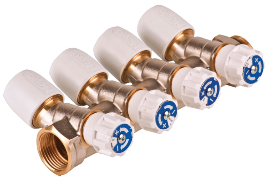
I installed my HEP2O system courtesy of @Nickfromwales guidance about 9 years ago. I have a one pipe-per-tap/appliance design, all fed from a central manifold setup (see image below). It works brilliantly: no hidden pipe joins to fail, any tap or appliance can be isolated at the central manifolds. I have one bugbear: the "easy to turn" taps are no longer easy to turn. So once every few years, I have to go through every isolation valve and crank it through the full travel using a rubber strap wrench - but with only perhaps a 30° stroke, this is a time consuming total pain. (Luckily, all potable water goes through a Harvey filter, so there is pretty much no pipe fur problem.) I started doing this because I needed to isolate one tap urgently after a failure and found I could no longer turn the value by hand, so ended up isolating the entire cold side, losing head at a tap then I could crank it in slow time, before turning the isolator open again. So my Q to all those out there who have the same HEP2O manifold setup: what do you do here? Do you bother doing an annual travel cycle? Do you have a key to turn these? If so what? I can't find a suitable turnkey online and Waverin doesn't seem to sell one. I did think about 3D printing a F/F key cap to ½" socket adaptor, so I can use a socket wrench on them. Suggestions gratefully received. Thanks.
-
chatGPT and the like for landscape inspiration
TerryE replied to Post and beam's topic in Boffin's Corner
Most AIs have a mix of good info and fantasy. The ratio varies by Agent and topic. Treat them a bit like advice from a friendly neighbour who thinks he is an expert on everything. The info might give you valuable insight, and options to explore, but it might also be total bollocks. So treat any advice as untrustworthy. Always validate this against other AI agents and independent reputable sources otherwise you risk getting badly burnt. -
Target U-values… Cost/benefit sense check… What am I missing? 🤷🏻♂️
TerryE replied to fatgus's topic in Heat Insulation
@fatgus I agree with your overall assertion that your design choices should be informed by through-life cost benefit trade-offs. You need to granularise to make doing this practice e.g. Wall U-value 2 vs 1.5 vs 1.2, etc. Also recognise that as-built might well vary from the design calcs due to mistakes in the design or construction quality issues: missing or sloppily fitted insulation, major leaks or missed thermal bridges. For example, our house works pretty much as design except that our slab losses are maybe 30-40% higher as build from a detail that caused edge bridging. So your heating / cooling system needs to have enough margin to cope with likely variations. Also remember that your heating / cooling system must be capable of adding / removing heat as needed. For example, we have a 3 storey house with only ground-floor in-slab UFH: no wall mounted rads and pipework anywhere; no heating on the top 2 floors. That is huge initial and ongoing cost-avoidance. See my blog for details. -
Interesting couple of days with the new heat pump.
TerryE replied to MikeSharp01's topic in Air Source Heat Pumps (ASHP)
My friendly Gemini AI gives me 17 kWh/K so (1) is the right ballpark. However, I can't recall Mike giving details on his slab dimensions and profile. You need some assumptions about the profile, so mine has ring beams cross beams etc with a 10cm fill-in for the slab itself. If you simplify this to a cuboid slab with area 11×7½ then the average depth is 35 cm which is too high. I am at a loss as to where (2) comes from. If the slab is sitting on 20cm PIR then the downward loss would be ~ 120W for a slab at 25 °C sitting on a subbase at 10 °C, plus the edge losses which should be smaller. The amount going usefully into the house is ~ 7×A×ΔT which more in the 2-3 kW pallpark if is ~ 5°C -
Interesting couple of days with the new heat pump.
TerryE replied to MikeSharp01's topic in Air Source Heat Pumps (ASHP)
No, that's me. 🤣 -
Interesting couple of days with the new heat pump.
TerryE replied to MikeSharp01's topic in Air Source Heat Pumps (ASHP)
Mike, one thing that you might try is get an idea of the time constant for the house at some point. Heat the house to some set-point and keep it at that for a couple of days, then tiurn off the heating for 24 hrs, say, and track how the house cools. We have low overall U-value loss, but high internal fabric total specific heat ("thermal mass"), so we lose maybe 1°C / per day with the heating off. This means that we can shift the heating windows to pretty much any time that the electricity costs are cheap and make maximum advantage of a ToD tariff. You might find the same, but some build techniques use a smaller slab volume inside the thermal envelope, plus low SH insulation so the time constant is shorter and the house loses 2-3 °C / per day. This impacts your best heating strategy, so it's a characteristic to understand. 🙂 -
Interesting couple of days with the new heat pump.
TerryE replied to MikeSharp01's topic in Air Source Heat Pumps (ASHP)
Mike, it looks very much as I'd expect, that is no surprises. I did warn you about the consequences of the 185s before you poured concrete but that conv obviously went into the information overload bin, but this falls into the 'it is what it is' category rather than something that needs fixing. The main consequence is that the flow speed is double what it would have been, with the increased circulation noise, and hit on your pump life. Your return temp is still 5°C more than room temp, so the avg slab surface temp is prob 7+°C warmer than the room env, and so you are dumping ~100W/m2 from the slab into the house, which seems to be heating the house by maybe 5°C per day. That's a hell of a lot for a passive class house, and you'll need nothing like that once the internal fabric is at target temp. You might want to experiment setting the house set-point to say 18°C and let the system reach equilibrium, leave a day or two; then step up the set-point another °C; rinse and repeat. That way you aren't going to be stressing anything too much. -
I've had ME/CFS hovering around in my life since my first collapse in my early thirties. Luckily I spiralled out into reasonably good health over the next year and for the next 25 years, albeit with the odd post viral wobble. However, I then had a second collapse in my mid 50s and was bedridden for more than a year and had to retire early. Again 8 years of slow recovery getting to a point in my 60s where we could take on the self build. This really was a sweet spot for us: we had the time, energy and enough capital to take it on. But TBH the build was gruelling and by the time we finished, I was "running on empty" so another ME collapse, and another year+ pretty much bedridden. So doing the build extracted a toll on my health and as I stretch into my 70s I am still dogged by fatigue problems. However we've downsized from an old stone farmhouse full of character (but also high-maintenance / expensive to heat and maintain) to a cosy and cheap to maintain modern passive-class home. At the same time we freed up some capital to help our kids on the housing ladder. So yes, it was all worth it, but it did have a life cost. I couldn't do this again.
-
+1 to Thanks for the update. We're all growing older. Jan and I are into our 70s now. We moved into our house a couple of months after you did. Overall we are delighted with our house, its environment and performance. We have made one change: we dumped the SunAmps for a decent UVC, and Jan is now keen to do a partial refresh of the kitchen, because some aspects of the design really grate. I hope all goes well with you both, all things considered. It would be good to get any further updates; A few of us are genuinely interested. 🙂
-
X3 Immersion heaters on a single radial
TerryE replied to RedSpottedSev's topic in Consumer Units, RCDs, MCBOs
You can get a range of contactors typically with 240VAC, 12VDC or 24VDC coil voltage. They all draw ballpark 1W to keep the contactor closed to the load on the control relay is ~40mA in the case of 24DVC, doubled for 12VDC, and a tenth of that for mains. I prefer using DC simply because all of the control stuff is low voltage which makes it easier to get signed off. -
My excuse is that the idiom is a US one. We would probably say "Do the sums". 🤣 I had a shower in my 20°C unheated en-suite earlier. I survived.


