
Super_Paulie
-
Posts
653 -
Joined
-
Last visited
-
Days Won
2
Everything posted by Super_Paulie
-

Joist very close to wall, pipe entry?
Super_Paulie replied to Super_Paulie's topic in General Plumbing
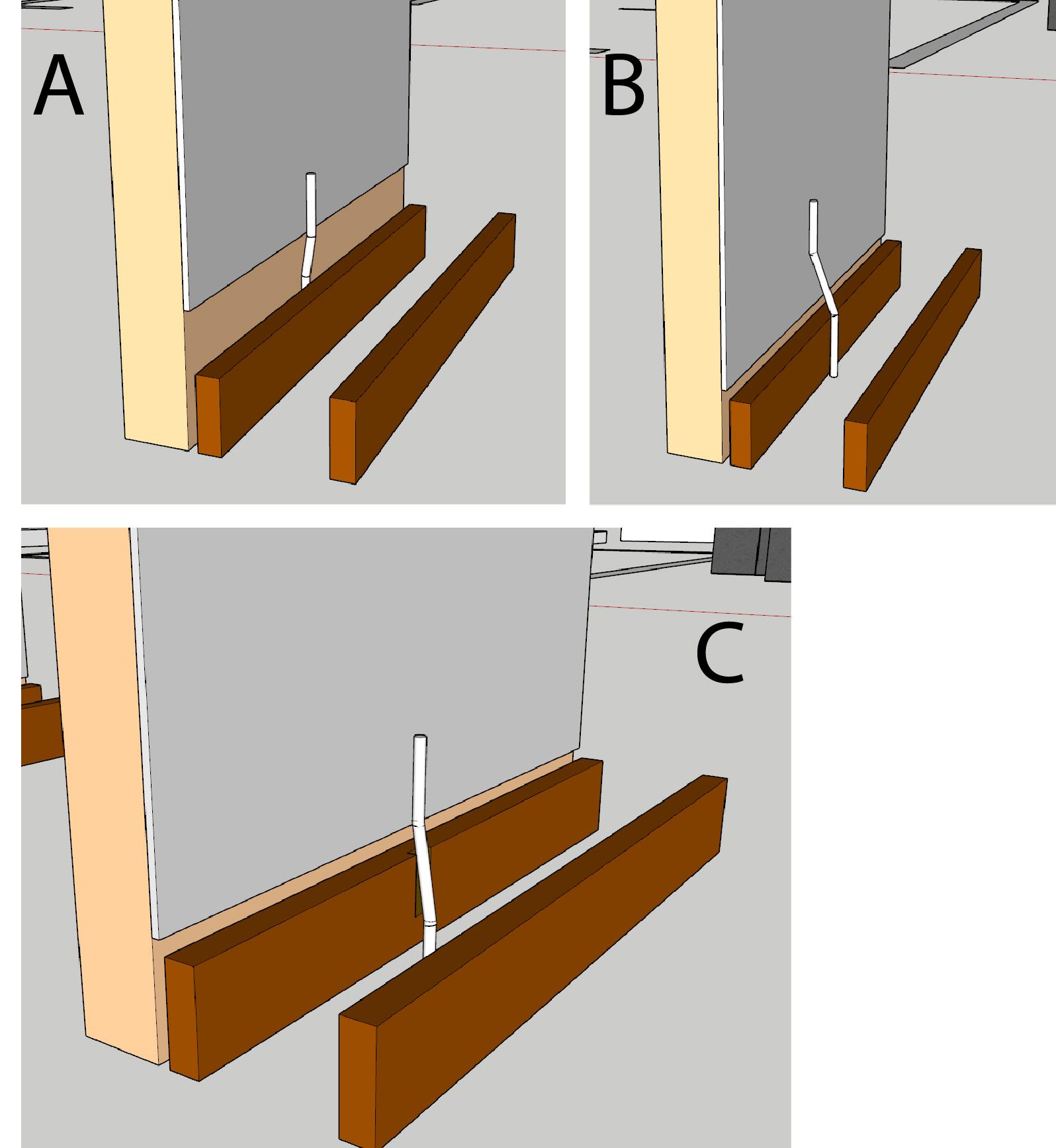
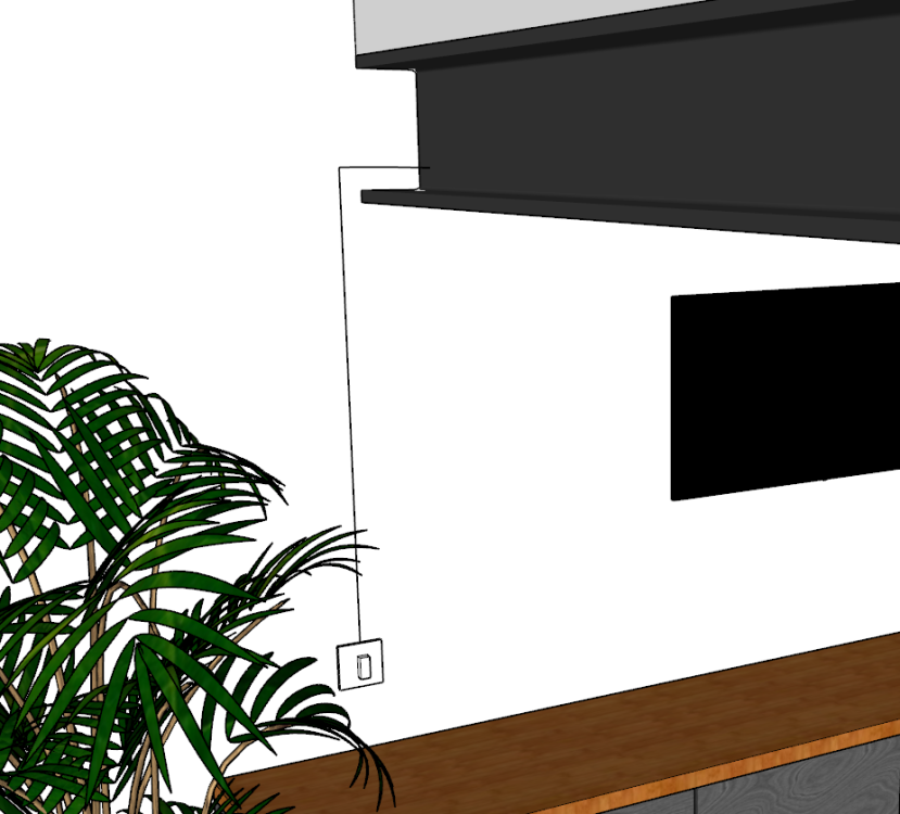
sounds like a winner. So something like this, coming out on the room side of the joist and straight up into the unit. Could easily cut the unit out so the unit can be slid out if ever necessary and a false back on magnets or whatever to conceal it all. (waste not shown in image, obvs)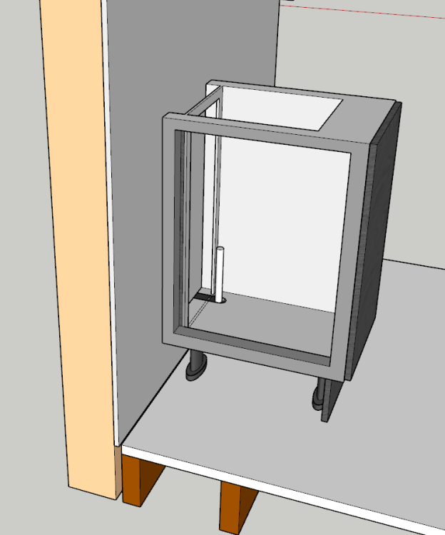
-
Joist very close to wall, pipe entry?
Super_Paulie replied to Super_Paulie's topic in General Plumbing
yeah this is coming up to the rear of a 300mm unit to the side of the washer. I could bring it up into the cupboard from the bottom like you say, i usually bring them up in the service void and then have a false back to conceal the workings so the cupboard is still free to use, and if i have major issues i can remove the cupboard and all the plumbing is still in-situ. However thinking about it i can see the advantages of having easier access to the valve the way you describe. -
Joist very close to wall, pipe entry?
Super_Paulie replied to Super_Paulie's topic in General Plumbing
pipe is 15mm. If i chase the wall then it seemingly would be difficult to get that to come out at 90degrees unless i convert to copper below floor level, the bend radius isnt great on the layflat in comparison to a copper 90. Not a bad shout though. -
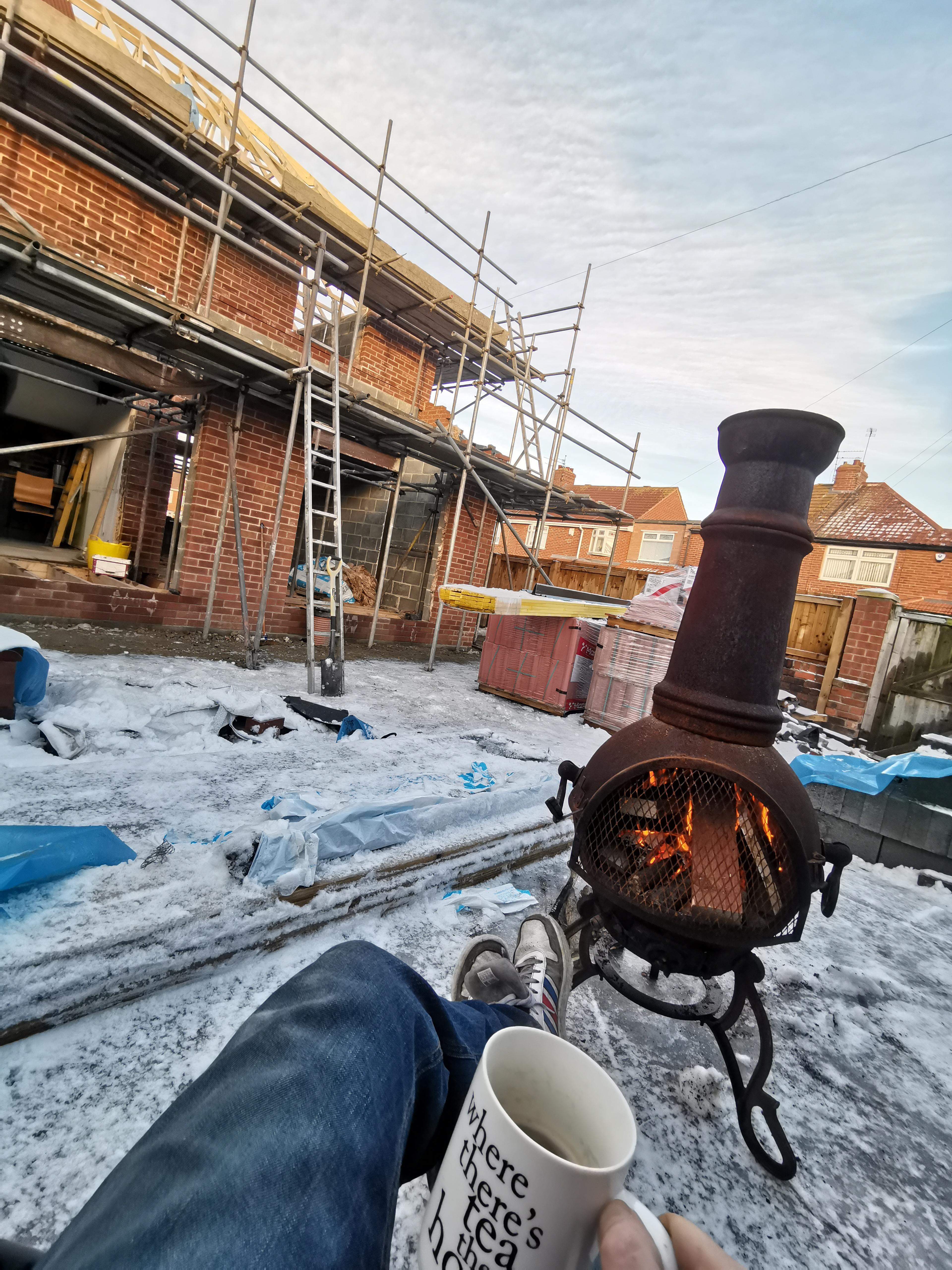
mornin. Pretty easy one for the guys this morning. Ive got a situation where i need to bring up my cold feed for the washing machine and the wall is very close to the joist. There will be units over the pipe work. The wall is back to bare brick so it will need boarding which makes it even more tricky as it will project at least 20mm further. Do i: A) bring up between the brick and joist, manipulate the pipe to bring it past the board and then clip. Means the board wont be able to go as low as i would ideally like, or i could cut a channel from it B) go the other side of the joist and manipulate it back over. Means i can board lower but the pipe will be exiting the floor quite far out is possibly further out than the service void of the units C) chamfer the joist. Probably no good as its taking too much structure away but i threw in the picture for reference D), convert plastic to copper under the floor and then bring copper up with a few 45 bends. Means a joint under the floor which i was trying to avoid. Any opinions on best practice?

-
the Smiths SS80 is designed for low plinths like Ikea ones, based on the name im thinking they need a plinth that is 80mm high. Still might be a stretch but you aint gunna get smaller than that i bet. Smiths SS80
-
Suspended Timber Floor insulation - critique my plans please.
Super_Paulie replied to SoliD's topic in Heat Insulation
i have 2 large rads and 2 plinth heaters in my large space (70sqm) as a backup for the UFH. Those plinth heaters really chuck out some heat, might be worth looking at if you have a lot of kitchen units. -
Suspended Timber Floor insulation - critique my plans please.
Super_Paulie replied to SoliD's topic in Heat Insulation
my "backup" radiators are the classical style i guess you'd call them, raw triple column and the heat they give out and retain compared to your standard radiator (that i have elsewhere) is unreal. They stay warm for hours afterwards when the others are stone cold. I have 22mm chipboard in mine which leaves me nervous for when i finally get round to commissioning it. If i could go back id defo get 18mm or a cement board of sorts but im all in now with the chipboard. -
Suspended Timber Floor insulation - critique my plans please.
Super_Paulie replied to SoliD's topic in Heat Insulation
@JohnMo is really clued up on this and might be able to advise you further. -
I wonder how the zones work around a beam like this... Might have to do some research on that one as I guess anything within 150mm from the ceiling and the wall is technically a zone. But where does that leave under the beam as it just ends rather than continue down.

-
Suspended Timber Floor insulation - critique my plans please.
Super_Paulie replied to SoliD's topic in Heat Insulation
i have my lower PIR attached by using clout nails into the battens and then pushing the 50mm into those nails so its held in that way, then foamed and taped. Then the 120mm over the top, staggering the joins and again foamed and taped. Yeah, the more insulation the better as far as im concerned, i have mine over the entire ground floor no matter if it has UFH over it or not, such as under the kitchen and island units. -
Suspended Timber Floor insulation - critique my plans please.
Super_Paulie replied to SoliD's topic in Heat Insulation
as long as the EPS70 doesnt enclose in the bottom of the joists it'll be ok. The bottoms need to be left exposed to the air under there. See attached for what i have done in my own in terms of insulation, the lower 50mm is held on nails and the whole lot foamed and taped in. So long as your UFH system and design is sound, i dont see any real issues. JohnMo and Nick on here will be along soon im imagine, i got most of my top quality info from them in terms of buffer tanks etc.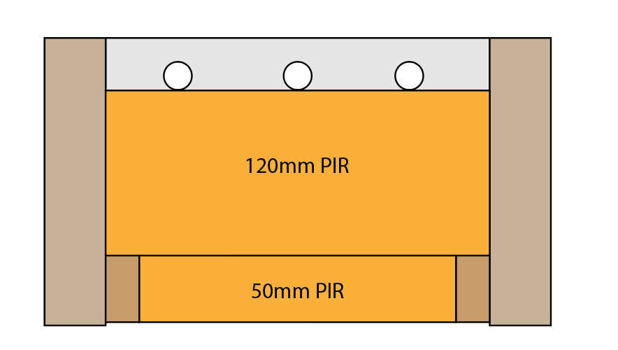
-
The problem with all of the ideas is that my wiring will be out of zone to get within the flange of the beam. I'd have to go down (or up) and then sideways towards the web. Going out of zone is surely a no-no but I can't see a way around it.
-
i guess this would be more accurate, but without a switch directly below it then id be out of zone.
-
so far there is zero wiring, so everything is still on the table. The idea of the socket was to plug in whatever, LED strip, fairly lights, i dont know, and have it controlled via a smart socket rather than having a physical switch. We have a lot of smart control in the house and this was just an addition i said id look into. Its just to be used on rare occasions/events/ id image (not at all). But yeah, looking at it a socket up there would be troublesome if the smart ever packs in. So a light switch below, that would create a zone as well, and an exit above with a transformer sat on the beam. I guess that would make the device (whatever it is) not really transferable to some other latest gimmick she likes.
-
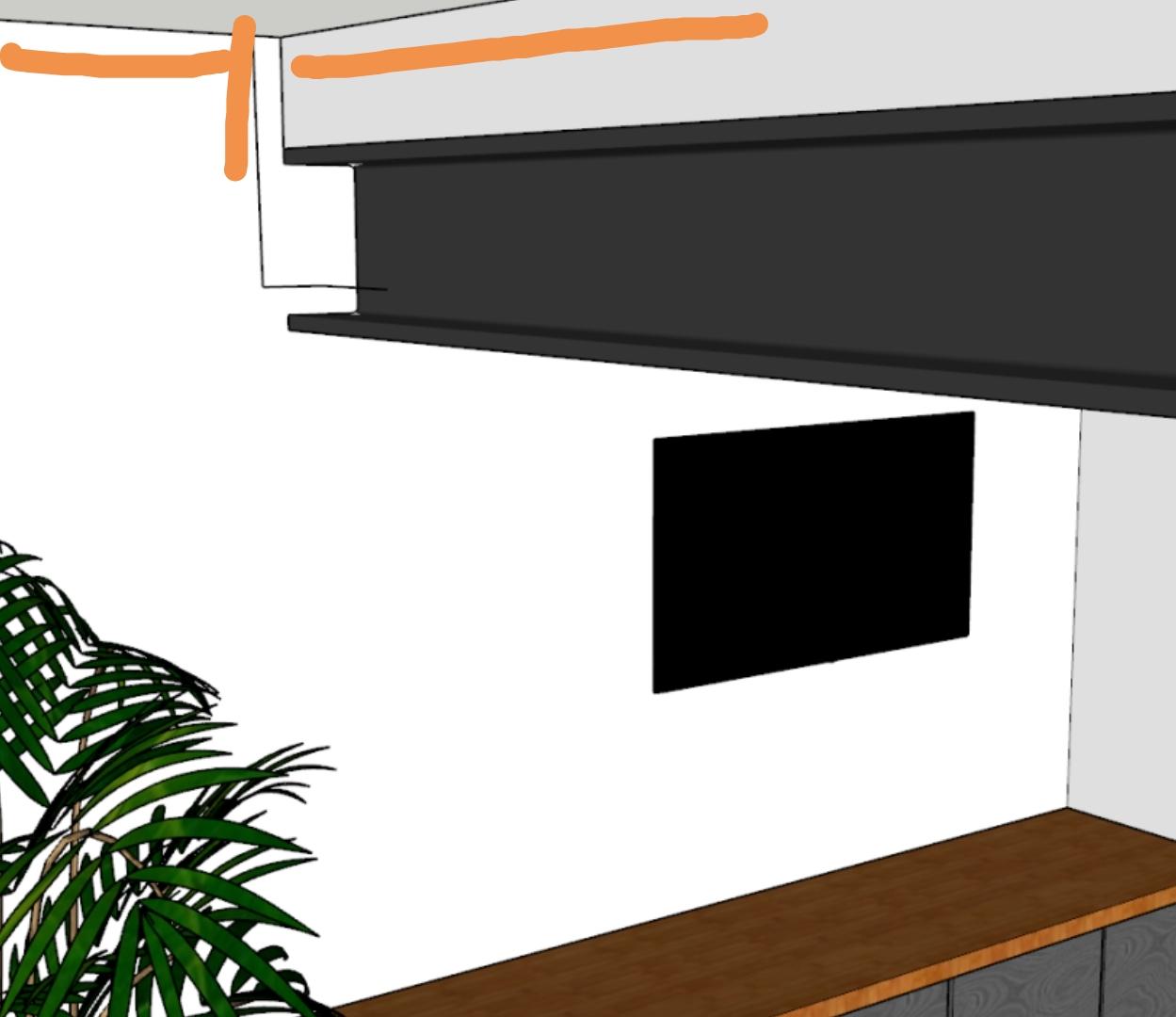
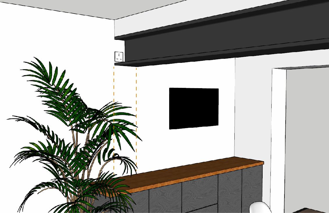
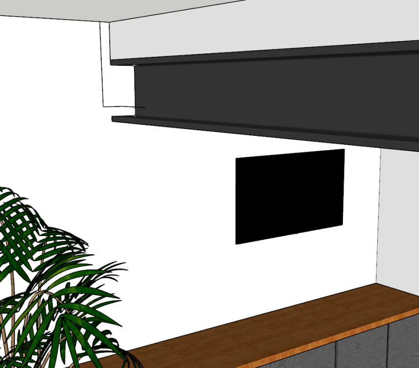
the missus has decided that having the option to plug in LED lighting along our exposed steel beam would be a nice idea. However im a bit stumped on how to achieve this as to get a socket within the flange of the beam seems impossible to do and keep the socket in a wiring zone, see attached. The only way seems to be having another socket horizontal to this one further along the wall but that doesnt sound great. I can come down from above but i wouldnt be able to get past the top flange of the beam. The dotted lines are the concealed steel post and the other end the beam rests of a brick/concrete pad stone, the wall to be clad with brick slips. Does anyone have any bright ideas on how i can achieve this, as im a bit stumped.


-
Sonoff smart relay - no neutral?
Super_Paulie replied to Super_Paulie's topic in Networks, AV, Security & Automation
how do you connect them? L-in live, L-out switched live. S1 to the live side of the switch and S2 the returned switched live? All my new switches have a neutral as i made it that way but my old part of the house doesnt, so these might be interesting. -
i hang my buffer tank on the wall with resin and threaded rod, it aint going anywhere. Could probably inject the resin into the hole and then drill and plug it again if thats the route you fancy.
-
Built-in fridge with ice dispenser
Super_Paulie replied to puntloos's topic in Kitchen & Household Appliances
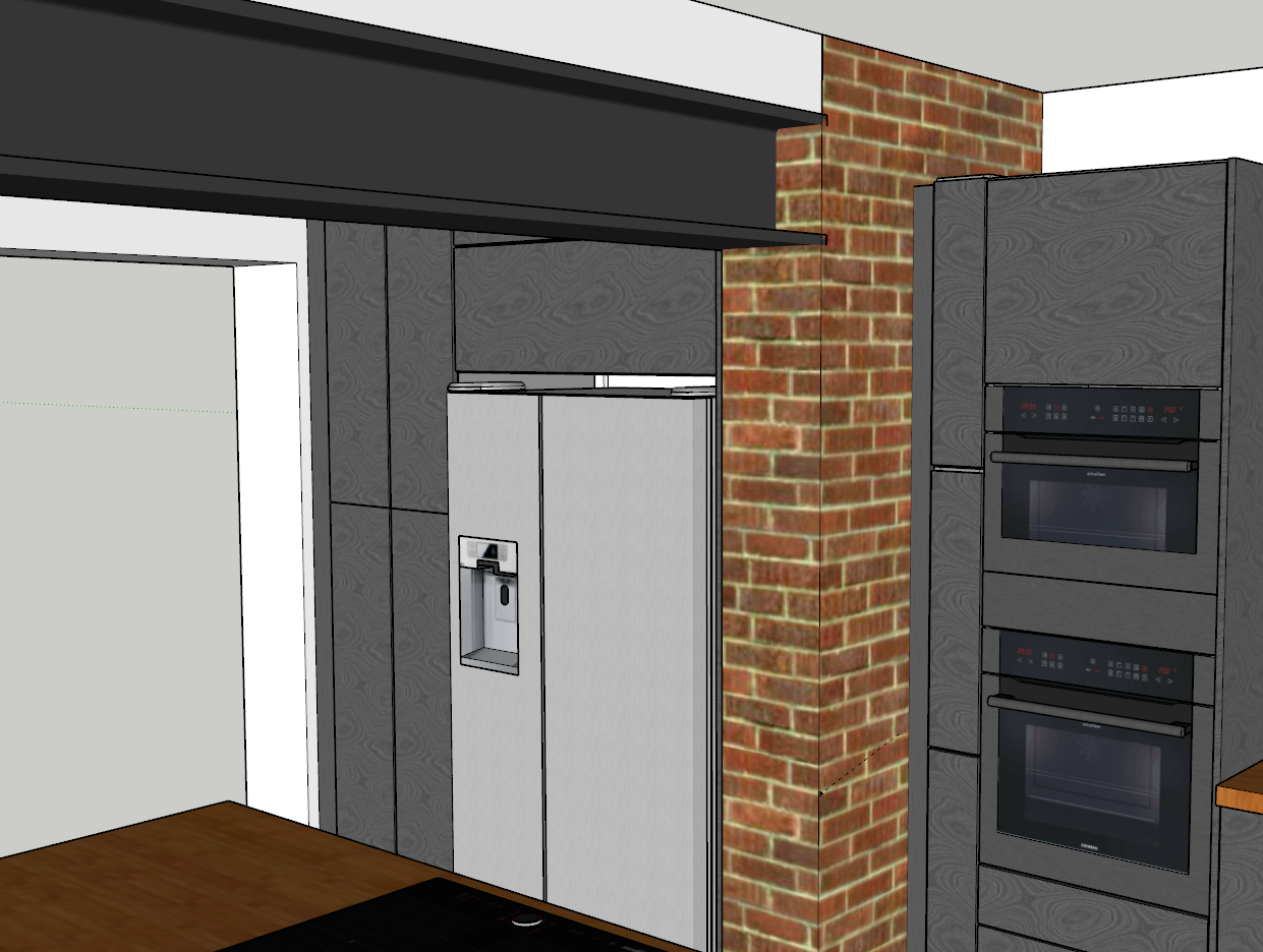
going through something similar, but different. My builder didnt leave a big enough return next to the bifolds so i need to get the slimmest possible due to the above that the doors need roughly 8cm protrusion to actually open. I found a Haier that was 66cm deep and a Beko that was 70.5cm but its frustrating that i cant just pick and choose which was going to be be initial intention. Even so id have to bang it up almost flush to the wall behind so id likely have to carve a recess out of the blockwork at the bottom and not plasterboard the whole area behind the fridge. Still probably blow up but got no real other option. -
Do you regret your ufh setup John? I'm yet to commission mine but it's happening imminently and I'm dubious myself. Too late now, but if I could go back I'd just fill the gaff with quad rads and be done with it.
-
id whack 100mm of PIR flush to the flooring and be done with it. If you can sacrifice any height from the room then you could overboard it with PIR as well but i probably wouldnt bother. 100mm should be a decent improvement if you can get it all air tight.
-
Pretty sure the bottom of the joists need to be exposed to air flow, that's probably why you can't find any examples of it online. I was in the same boat in my original part of the house, could only get 100mm of pir into it. Not a lot I could do about it without major surgery.
-
Heat loss via external drain cock?
Super_Paulie replied to Super_Paulie's topic in Central Heating (Radiators)
That was my initial idea but the wife had other plans with some fancy valves, copper left on show etc... Not planning on doing it a lot, it's just while the gaff is a building site now would be the time. I'm still in 2 minds about it... -
Heat loss via external drain cock?
Super_Paulie replied to Super_Paulie's topic in Central Heating (Radiators)
Nah that won't matter really, it's just to get rid of the majority at radiator level. Im just unsure as to having the cock outside is essentially losing a shed load of heat at all times. I could probably have it on an isolator but that would haveto be under floor level, so mightily inconvenient. -
Heat loss via external drain cock?
Super_Paulie replied to Super_Paulie's topic in Central Heating (Radiators)
It just seemed an easier way to get rid of a ton of old heating water as the cock would be directly over a gully. -
Morning everyone, nice and warm today. I'm looking to fit an external drain cock to completely drain the central heating when the need arises. So the lowest point is obviously under the floor and I was going to just tee into the closest rad flow and bring the pipe straight out the wall with the cock on the end, a run of maybe 40cm, pretty simple stuff. But my question is, am I just going to be haemorrhaging heat outside via the drain cock? As it's all under the floor level I can't really get an isolator that I can access on there. Water won't be flowing through the leg but the heat will transfer through the water/pipe. Or am I worrying about nothing here as it will be miniscule? Cheers guys.