Jeremy Harris
-
Posts
26430 -
Joined
-
Last visited
-
Days Won
360
Everything posted by Jeremy Harris
-

Current draw of a wax solenoid?
Jeremy Harris replied to MJNewton's topic in Mechanical Ventilation with Heat Recovery (MVHR)
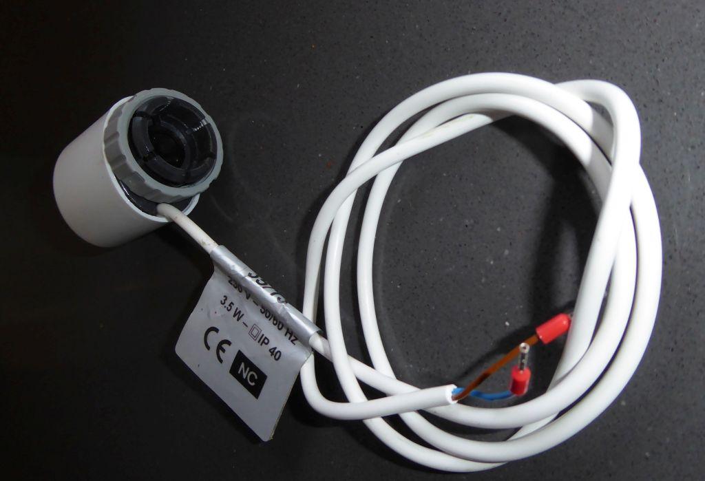
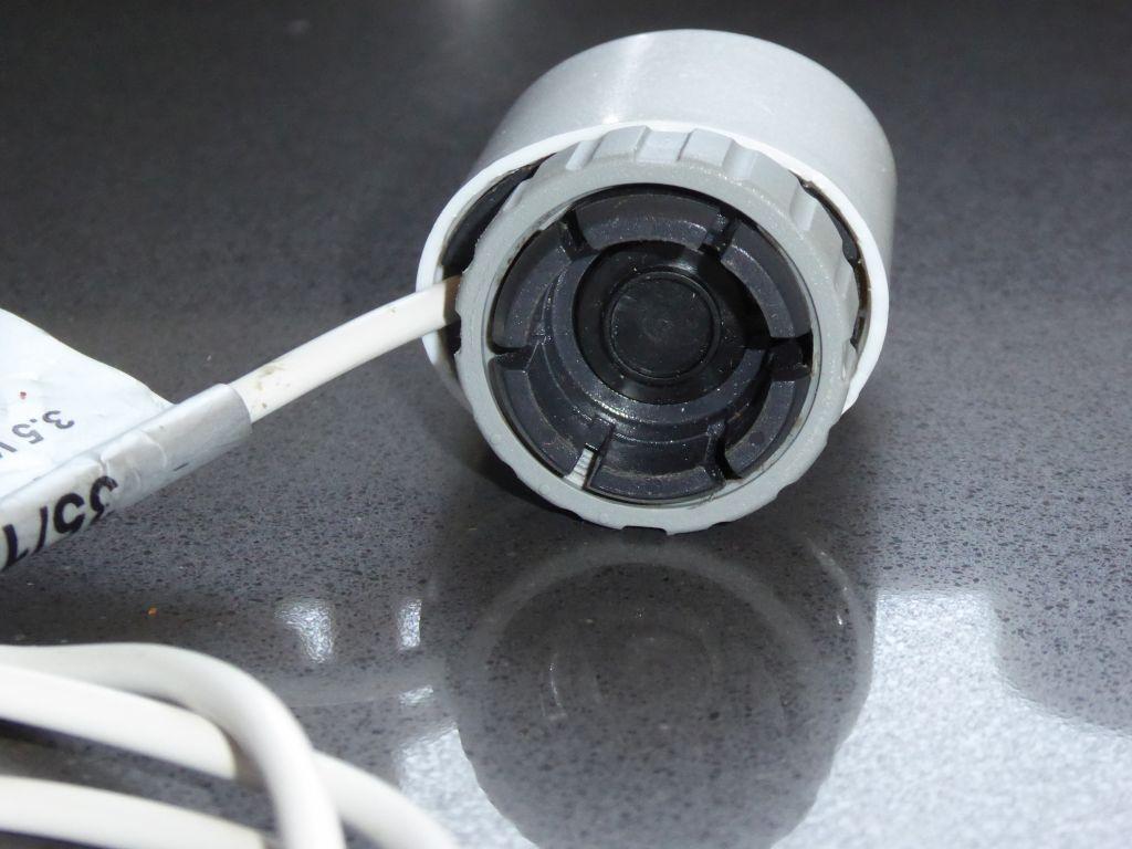
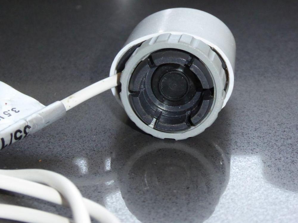
Here's a couple of photos of a typical UFH wax operated actuator. This one has a 3.5 W heating element that takes around 5 minutes to fully open the valve:
-
+1 to using anaerobic sealant. I discovered the Screwfix Liquid PTFE, a few years ago. Works exactly like Loctite sealant, even smells the same, and gives a guaranteed watertight seal every time. My only gripe is that the bottle is a PITA to use, as the stuff is a bit too thick to pour, so you end up having to really squish the bottle to get the stuff out: https://www.screwfix.com/p/flomasta-ptfe-liquid-50g/5321j
-
Current draw of a wax solenoid?
Jeremy Harris replied to MJNewton's topic in Mechanical Ventilation with Heat Recovery (MVHR)
Just looked at an old UFH actuator and the label gives the power consumption as being 3.5 W It seems to move by about 4 or 5mm at a guess, so not much. -
Current draw of a wax solenoid?
Jeremy Harris replied to MJNewton's topic in Mechanical Ventilation with Heat Recovery (MVHR)
6 W sounds reasonable for a fairly powerful/wide movement range wax stat. UFH actuators are probably a fair bit less power (tiny range of movement and modest force) and they tend to be around 2 W to 4 W. -
+1 to the above re: 400mm centres. The last timber framed house we lived in had studs at 600mm centres, and by comparison this house feels noticeably more solid. You notice it especially if a door bangs, when there's virtually no shake anywhere.
-
It depends very much on the total load, both on the installation at the end of each sub-main, and on the incomer. This needs to be determined and stated on the lodged EIC by the competent person undertaking, inspecting, testing and signing off the work, so before getting materials a few things must be done. Firstly, the actual rating of the incoming supply needs to be determined. This could be as high as 100 A, but may be as low as 40 A. The DNO will do this on request (they have to do it, as the fuse is their property). Next the total load at each installation (in this case the house, flat, barn 1 and barn 2) needs to be determined, or measured in a representative way. Bear in mind that fuses don't rupture at all quickly for modest overloads, so you cannot use a fuse rating to determine the maximum load (for example, a BS88 100 A fuse can take about 10 minutes to rupture at 200 A, or maybe 5 hours to rupture at 150 A). For an existing installation it may be possible to do a 24 hour peak load measurement to get a feel for the true load, which is OK if done at a time likely to be representative. The other way to do it is to calculate the load, using the expected circuit loads, allowing for diversity where applicable. For example, here's a sample calculation for a fairly typical domestic installation: 2 off ring final circuits, with 32 A over current protection 2 off lighting circuits, with 6 A over current protection 1 off cooker circuit, with 40 A over current protection, supplying a cooker rated at 7 kW maximum, with no additional 13 A outlet 1 off immersion heater circuit, with 20 A over current protection, supplying a 3 kW immersion heater load. The two ring finals are calculated as presenting a load of 100% of the total up to 10 A, plus 50% of anything over 10 A, so would be 10 A + (50% x (32 A - 10 A)) = 21 A each, 42 A in total The two light lighting circuits are calculated as presenting a load of 66% of the total, so 6 A x 66% = 3.96 A each, ~8 A in total The cooker circuit (7 kW / 230 V = ~30.4 A), is calculated as presenting a load of 10 A + (30% x (30.4 A - 10A)) = ~16 A in total The immersion heater circuit presents a total load of 3000 / 230 = ~13 A in total (diversity cannot be applied to water heaters or electric heating) Adding up the total from the above calculations gives a total load from this installation of ~79 A There are ways to reduce the total load by using load priority devices, or by restricting the maximum load on some circuits. I suspect you may well have to consider doing this if your total load looks as if it will exceed the rating of the incoming supply. The competent person that must do this work and sign it off (this cannot be DIY'ed, I'm afraid) may be able to suggest ways to keep things within limits and safe, if this is practical to do. It's possible to reduce the rating of ring final circuits, perhaps, if the loads are only ever likely to be fairly low, or it may be possible to wire one or more of the sub-mains with some form of load limiting or priority load relay system.
-
Best to use 3 core SWA if exporting the PE, IMHO. That way there's a high degree of integrity in the connection, as it's not reliant on the galvanised steel wires always providing a very low impedance connection. If the installations are going to be wired with earth electrodes, as TT, then the CPC from the CU in that diagram would go to the earth electrode and the armour CPC would be isolated from the installation. Inside the box (would need to be a reasonably big one) you'd just have two Henleys (one for line, one for neutral) plus an earth block. The earth block needs enough ways to accept the various CPCs, so for the set up above it would need 5 ways. If really stuck for space you could use a double decker Henley, but personally I'm not a great fan of them, and much prefer to keep the line and neutral terminations separate.
-
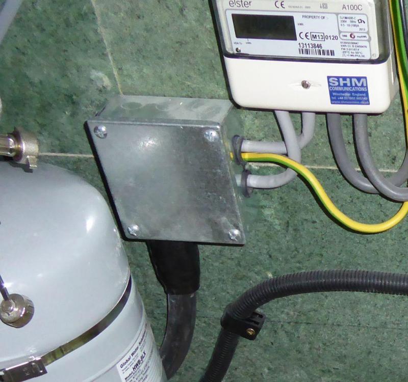
Just found this photo showing a bit of 25mm² SWA terminating in a small 4 x 4 adaptable box, with tails fed out to the CU. There's no Henleys inside, just an earth block to terminate the armour and cable CPC and allow a 10mm² CPC to be fed out to the CU, along with the sleeved live cores from the SWA. Worth noting that there's a slot cut between the two grommets where the tails come out, to break the magnetic circuit that would otherwise be formed by the steel of the box. The meter in this photo is a private one, not the suppliers.
-
I don't have a photo to hand, but I've done it in the past and it's easy enough. just fit glands in the box for the SWA and fix a couple of Henleys and an earth block inside, screwed through the back to the base board. Needs one of the larger adaptable boxes so there's enough room, but easy enough to do. I always tend to use piranha nuts on SWA glands now, as they are a lot easier than faffing around with brass banjos.
-
Some progress, although I'm still waiting for stuff to arrive. Rather bizarrely, the only thing ordered from China, a supposed "hypochlorous acid generator" has been the first thing to arrive. This is what it looks like: First thing I did was take it apart to see what's inside and how it works. It is really simple, just a timer circuit that switches a controlled current through a couple of titanium electrodes that spiral around the base, and which are covered with a plastic grille. The timer runs for 8 minutes when the button is pressed. All the instructions are in Chinese and are indecipherable (I've spent an hour trying to just get the basics, to no avail). I went back to basic chemistry and decided that the starter solution probably needed to be about 1.2g of sodium chloride to 300ml of water electrolysed for 8 minutes at about 1 A, in order to give a solution with about 500 to 800ppm of hypochlorous acid (that's a pretty strong disinfectant, 50ppm would probably just about be OK). This thing cannot just produce hypochlorous acid, and produces a fair bit of sodium hydroxide in the end solution. Not enough to cause any significant harm, and it may well mean the solution is a bit better at cleaning surfaces. The main issue is that the pH increases way above the point where the hypochlorous can remain stable for long. I ended up with a final pH of around 8, and ideally this needs to be below 5, perhaps down around 3 to give a few weeks of shelf life. I've tried to assess the free chlorine, as a crude measure of hypochlorous acid concentration, but failed, as my test kit can't work up at this range, which bodes well for it actually having worked (as does the slight smell of chlorine). I have some stuff on order, including a high range chlorine test kit, that should allow a better assessment of the effectiveness of this thing. I also have some acetic acid on order, as I want to try lowering the pH to see how that impacts the shelf life. I'd like to try using very cold water as a starter, too, as that may increase the solubility of the chlorine gas liberated from the anode in the water. The hydrogen liberated from the cathode when the thing is running is just vented to the air. Also on order are some larger titanium electrodes, as I want to have a go at making a proper hypochlorous acid generator, one that separates out the hypochlorous acid from the sodium hydroxide, and allows better control of the pH. This will need an ion exchange membrane to separate the anode and cathode, but I'm hoping I can knock something up using standard waste pipe fittings. More to follow once I get more stuff delivered.

-
You could add a Henley inside an enclosure, then run either tails or other runs of SWA from that. You need the enclosure so that the SWA cable glands have something to fit to, and to protect the single insulated SWA cores from being able to be touched.
-
You can't easily terminate SWA in a Henley, needs a metal enclosure to accept the cable gland, as the cores of the SWA must either be enclosed or have an additional insulating sleeve fitted over them so they are double insulated if exposed (as they probably would be when going into a Henley). You can do as I did and fit an SWA gland to a metal enclosure, then double insulate the SWA live cores (line and neutral) and run those to a CU just like meter tails (meter tails come pre-double insulated). This saves additional interconnection points, which is generally a good thing. You need to do the max load calcs, both to size the cables, etc and to determine whether the total load is within the incomer rating. This means adding up all the circuit loads, applying diversity where applicable, and then demonstrating that the total load won't exceed any of the ratings. This isn't optional - whoever signs this off (and it's notifiable work under Part P) will be signing to state they have assessed the total load. You may need to ask the DNO for the incomer rating. Incomer fuse heads are now often marked "100 A", but that isn't necessarily the rating of the fuse. It's not at all uncommon to find a 100 A carrier fitted with a 60 A or 80 A fuse, I've even seen a 40 A fuse fitted once. You cannot cut the seal and check the fuse, that has to be done by the DNO, or, perhaps, a meter fitter from the supplier, if they are there to replace/fit a new meter.
-
The over-current protection for the 16mm² SWA needs to be at the supply end, so a DP fused switch with a 60 A fuse, like this: https://www.tlc-direct.co.uk/Products/CGFS100.html This is required to protect the cable. RCDs don't provide over current protection, their job is only to provide residual current protection should there be an earth leakage fault. An RCBO can provide combined over current protection and residual current protection. One way to calculate the total demand is to assess the loads within each circuit, apply the diversity rule, and then see what the total may be. An acceptable alternative is to measure the load over a representative period of time, using a peak hold clampmeter, and then use that as a guide to the total load. The diversity guidance is contained within the OSG, if you list the appliances and their maximum ratings, together with the circuits and their rated current, one of us can have a stab at doing the sums. The diversity rule works on the basis that it's unlikely for some appliances to draw their maximum rated current for long periods, together with the fact that it takes time for any overload protection device to open, if the overload is only modest (can take hours for a modestly overloaded fuse to blow, for example). Some circuits/appliances cannot have diversity applied, as they draw their rated power for long periods of time. Examples are water heaters, car charge points, electric heating etc. The choice as to whether to export the PE from the incoming supply to a distant outbuilding depends on the distance, the protection provided to the cable and whether or not there is an enhanced risk of shock from exposed conductive parts at the remote end. For example, a car charge point will often be wired as a TT installation, with an earth electrode close to the charge point, as this ensures that the exposed bodywork should remain close to the local ground potential if there was a fault. My garage is wired like this, as it has a concrete floor and metalclad outlets, so I wanted to be confident that the local ground would be close to the same potential of the exposed conductive parts in the event of a fault upstream from the installation. The voltage drop for 50m of 16mm² 3 core SWA buried in the ground will be around 7.5 V at 60 A. This is just about acceptable, but 60 A is close to the limit for 16mm², which seems to be about 67 A (according to the TLC voltage drop calculator: https://www.tlc-direct.co.uk/Technical/Charts/VoltageDrop.html ). SWA current ratings do vary a bit from one supplier to another, though, for some reason (often related to the temperature rating of the cable). Often the limit will be the lower maximum temperature that the fittings at the end of the cables will tolerate.
-
Welcome. What's protecting the 16mm² SWA from over-current? It needs a fuse at the isolator, as you're only permitted a maximum 3m run of 25mm² tails from the meter without additional protection. Exporting the PE can be OK, depends on the distance and the risk from a PE - N fault on the incoming supply (which will now include the run of SWA). For example, I ran a ~15m length of 25mm² 3 core SWA from our meter cabinet to the house, with the SWA terminated at the house end at a metal enclosure, with 25mm² tails from that enclosure to the CU (I just double sleeved the SWA cores to create tails, rather than make an additional connection). The PE is imported via both the CPC in the 25mm² and the armour. For our detached garage supply, and my car charge point, I ran 2 core SWA from an external CU next to the meter box, with the armour isolated at one end. Those two circuits are both wired as TT installations, with the appropriate RCD protection. The final check would be to see what the voltage drop is going to be at each end point, for the typical max demand that's predicted. If the cable run is long you may need to increase the size of it from 16mm² to 25mm², perhaps more.
-
Woodland cabin build
Jeremy Harris replied to Waterworks's topic in General Self Build & DIY Discussion
Are the frames for that CNC cut ply? -
Me too. We held an oak sleeper wall together with stainless steel rebar, driven into slightly undersized holes. Worked a treat. The chap that built our wall this way reckoned that it had to be stainless, as oak will attack ordinary steel fairly quickly.
-
I read a post on another forum by a character saying that he'd hooked up a load of electric heaters in the garden so that he could earn more money from negative pricing. . . The peak rate kills it for us, too, as does the normally slightly higher rate over the whole overnight period. Moot point, anyway, as with no mobile signal we couldn't have a smart meter even if we wanted one.
-
Air leak on the inlet side? It doesn't take much to interfere with the way the pump draws in paint, just a pinhole somewhere in the inlet pipe might be enough.
-
Can't build house so making shepherd's hut / site hut
Jeremy Harris replied to MortarThePoint's topic in Garages & Workshops
Somehow that conjured up the image of an underfloor waste tank with a glazed porthole on the top . . . -
£23k for power for three houses seems reasonable, to me. I think others here have paid more than that to get power to a single plot. FWIW, the cost to supply mains water to our site was going to be about £23k, the cost of running mains drainage was going to be about another £14k and the cost to run electricity was about £3.5k. That was for a single small building plot in the middle of a village.
-
Warnings of COVID Power Cuts
Jeremy Harris replied to Ferdinand's topic in General Self Build & DIY Discussion
Underground cables are a lot more reliable, but cost a great deal more to install, so the DNO preference for running cables overhead is mainly to do with initial cost. When I offered to put in a duct to re-route an overhead cable underground the DNO were pleased to do it, and the chap that came around told me that he wished that more of their network was underground, as those were the parts that rarely caused him any problems. -
I had to fit flow restrictors to all our taps and the shower (nit-picking inspector - not actually needed) and I kept some of them after the house was signed off. The shower sas a 9 litre/minute restrictor fitted, and it doesn't seem to affect the flow to any noticeable degree. The 4 litre/minute flow restrictors fitted to the wash basin taps are great, as they stop pretty much all the splashing and make the taps easier to control, so we kept those too. The only restrictors I removed after completion were those on the bath taps, as restricting the flow through them seemed daft; you want the bath to fill as quickly as possible.
-
That sounds like a "submariner's shower". They had a water rationing, so adopted a similar technique. I actually measured the length of time that the shower ran for, for about a week, to get an average. The shortest time was me, about 6 minutes, longest was one when my wife washed her hair, about 15 minutes.
-
I've heard this mentioned a few times, and believed it to be true until I did some measurements at our old house to test it. We had a pretty average shower there, which used about 10 litres/min of water at 38°C. For anyone with a more powerful shower, say a rainfall type head, the flow rate will almost certainly be higher than 10 litres/minute. I measured the bath and it held about 80 litres of water at about the same temperature. I also measured the time that the shower ran for, varied a lot, but the average was around 10 minutes actual shower running time, so about 100 litres. Unless you have a large bath, it looks like taking a bath may well use less water than running a shower, perhaps by around 20% or so.
-
I can put some numbers to our electricity usage. We pay about £50/month for electricity, including charging my car, heating and ventilating the house, and delivering hot water. Most of that (around 70% at the moment) is at 8.148p/kWh. The percentage of cheaper tariff electricity, if we switched to Go or Agile would decrease to around 50%, and the percentage of peak rate electricity would increase, just because we can't easily adapt usage to fit in with shorter cheap rate periods (without investing in battery storage). The saving we could make from installing battery storage would be around £150 to £200/year, from a combination of better utilising PV generation (not a great benefit, as there's only really an excess when we don't use much electricity) and being able to partially take advantage of a flexible tariff. That's nowhere near enough of a saving to justify investing in a battery system, especially as we continue to receive the FiT and export payments of ~£1000 a year. The latter means we don't pay anything at all for energy, in reality, and we have another 14 years to go like that.