


DaveSpils
-
Posts
9 -
Joined
-
Last visited
DaveSpils's Achievements
New Member (2/5)
0
Reputation
-
Yes, you are of course correct with respect to the earthing. My diagram was a little generalized... If you recall from my earlier diagram, I plan to leave the flat as is fed by a 6mm2 3-core SWA and therefore will use the CPC from the consumer unit in the main house to provide the earth for the flat (as it currently does). However, the feed to the barns (because of their distance), I planned to use 16mm2 (or 25mm2??) 2-core SWA and use a TT earth for those. Therefore, the SWA for the barns will be isolated from the TT earth as it will be connected all the way back to the CPC in the consumer unit in the main house. Does that make sense? Dave
-
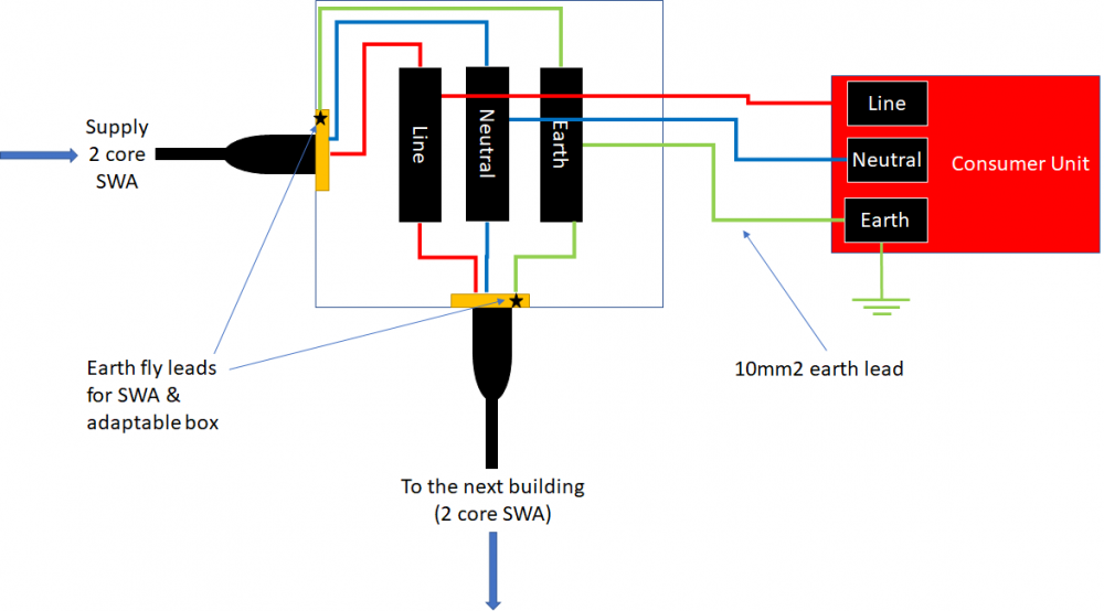
Thanks for the picture. I understand that at Barn 2 would look similar to this as the SWA is terminated. I just cannot envisage what it would look like inside the adaptable box for where I have a Henley Block. Is there a fixing for a Henley Block inside the adaptable box? Sorry to labour the point. Here is what I think is needed: I just looked at the Piranha nuts too - much easier.
-
@Jeremy Harris could I ask a favour of you please? Do you have a picture/example of an adaptable box with a Henley block (or similar) showing one incoming SWA and 2 outgoing SWAs? I have searched for one and cannot find any. Does the Henley block get fixed inside the box or is it loose? Is there another solution to this? thanks Dave
-
@Jeremy Harris Many thanks for this. I incorporated a Henley block as a way to "split" the SWA in 2 directions (to the CU and continue to the next building). I understand how I can connect it to a metal box using a cable gland but how do you take 2 feeds from this, one for the CU and the other to go to the next building? I may be misunderstanding this - sorry if I am!
-
@PeterW Many thanks. Do you mean at the position already highlighted (black circle with ?) and also one just before the CU in Barn2?
-
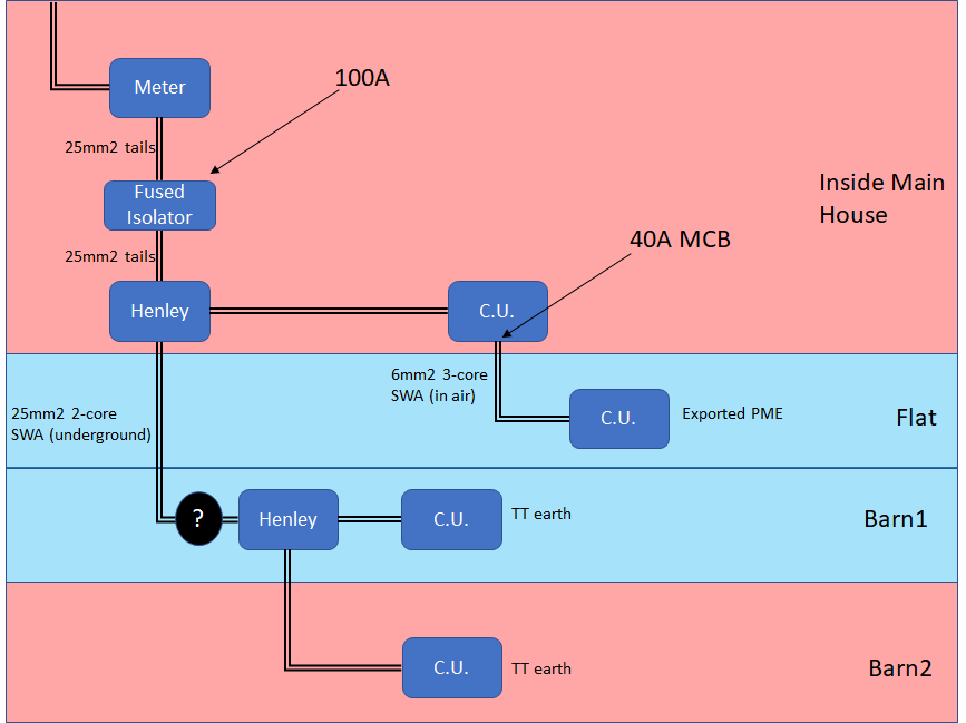
Does this diagram make more sense? 1. Remove my current 100A isolator and get a new fused 100A isolator (as advised) and position between the Meter and Henley block in the house. 2. I know the flat has never consumed more than 40A and so happy with the current set up of the 6mm2 3-core SWA supplying power to the flat, which also uses the earth from the main house (exported PME). So, I know long-term, 40A has never been reached. In air, 6mm2 SWA good for 56A so I see no issue with this. 3. From the same Henley block in the main house, run 25mm2 2-core SWA to a Henley block in Barn 1 (3 core not needed). 4. From this Henley block, go the the CU in Barn 1 and CU in Barn 2. 5. Both barns use a TT earth. The Total Load (main house + flat + barns) cannot exceed 100A due to the fused isolator and if it does, ALL power will be shut off. This is the limit of the CU in the main house also and protects all the SWA cables. If the voltage drop is not too severe, I could even use 2-core 16mm2 as the Total Load for the barns will be way below capacity of this cable. But, I would need a second fused isolator (63A or 80A) to protect this segment. Could I position this isolator in Barn1 just before the Henley block (shown by the black circle with a question mark)? Additional question - typically, what is the maximum current that can be drawn into the property before the main fuse is blown? I assume this is pretty standard across most "normal" properties. Thanks Dave
-
Thanks for the replies. @Jeremy Harris The "Meter --> Isolator --> Henley --> CU" are all contained in the cupboard within the house so we are talking "cm" not "m" in length of the tails. The isolator was put in by an electrician to provide a SWA to a charge point for an electric car we once had (7KW supply). We no longer have this and will disconnect that SWA from the Henley and use it (potentially!) for a SWA to the flat - this is where the proposed 16mm2 SWA starts (coming out of the first Henley block in the diagram). But you are correct, there is nothing protecting the 16mm2 from overload, other than the RCDs within each CU of the 3 buildings (I assume the SUM of the RCDs should be less than 75A for 16mm2). However, in air, the maximum current is 99A (75A under ground) for a 16mm2 - which it will be between the house and flat (flat to the barns is underground). Still, same applies, it needs to be protected so it is impossible to draw more current than it is designed to deal with. What do you recommend? The distance is quite far. The flat is about 15m away (in air); barn1 is about another 50m (mostly underground) and the final barn a further 15m (underground) - so these are the distances between each Henley block in my diagram and the final Henley block and CU in Barn2. So the total length from house to barn2 is about 80m of cable. May be 25mm2 is the correct size for this length taking into account the voltage drop. @ProDave In terms of demand, it could be quite high if all 3 buildings were at maximum draw - but this will not happen. Barn 2 is low load (lights and sockets) but Barn 1 and the Flat are potentially high load (in addition to the main house). However, it needs to be safe. The cable that supplies the power to the house I assume has a very high working maximum current - but what is that typically? So long as that is larger than what I need (with all buildings at their maximum), then I need to ensure each feed has the correct SWA with appropriate protection against overload. The flat is currently fed with 10mm2 cable from a MCB in the house (40A). It has never tripped despite there being an induction hob and oven (each can draw up to 30A maximum), plus small fridge, kettle and TV and the obvious (lights and available sockets). However, I assumed it would be better to take the feed from the Henley block and not from the 40A MCB within the CU of the house (please correct me if I am wrong!). The CU in the flat can draw up to 63A (theoretically) before the RCD trips but it will trip in the house way before then at 40A - which it never has. Taking the feed from a Henley block instead means the flat could draw up to 63A and the existing cable (10mm2) would still be adequate but I plan to change to 16mm2. Barn 1 will be used for my home brewing hobby and will include 2 water heating elements rated at a total of 5KW, so ~20A in total, plus lighting, fridge and sockets available for miscellaneous. The elements will only be on when brewing (2-3 days per month at most) and most of the time, only 1 element will be in use (~3KW). Otherwise, very low load. Barn 2 will be very low load - lights and sockets for miscellaneous use. Also, sounds like a TT setup is advised but would I need this for all 3 buildings? Currently, the flat uses the earth from the house and never had any issues. But Barn 1 and Barn 2 are much further down the garden and therefore does this mean a TT is advisable for these? 2 foot down in my garden and you hit bedrock - is this an issue for the earthing rod? I assume that if a TT is used, only 2 core SWA is needed (would still connect the SWA to the earth from the house but isolate at the other end). Dave
-
-
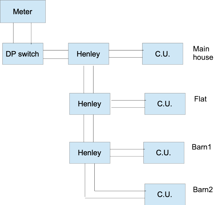
Hi I need to provide power to 3 external buildings - a small flat and 2 barns - without the need for 3 separate SWA cables. In the main house, I already have a 100A 2 pole isolator switch between the meter and a Henley block. From the Henley block tails supply the power to the CU for the main house. I plan to have a 16mm2 SWA also from the same Henley block to feed power to the flat. In the flat, the SWA will enter a Henley block. From this Henley block, I will then have a feed to the CU of the flat and the other feed to the first barn. Same in the first barn where it has a Henly block and again 2 exits from it to the CU in the barn and the other providing a feed to the second barn. In the 2nd barn, the SWA simply goes directly to its CU. So, there is a "continuous" 16mm2 SWA cable that provides power to all 3 buildings with a feed into each CU per building from a Henley block (I have estimated the expected total load to be lower than 75A, which is the operating limit for 16mm2 underground). I would like to know if this sounds acceptable? I may even add an additional 2 pole isolator switch in each building to isolate each without affecting any other building downstream. The other query I have is earthing. The main house is a TN-C-S system. The flat is brick and the barns are wood (all on concrete bases). There is a water supply to the buildings and therefore 10mm2 bonding will be used. I assume it is fine to use an "exported PME" - to use the earth provided by the supplier (the earth in the house), rather than using a TT earth local to the buildings. Sorry if not clear, I can provide a drawing if required. Thanks Dave
