
Nickfromwales
-
Posts
31378 -
Joined
-
Last visited
-
Days Won
346
Everything posted by Nickfromwales
-
 So, a potential service cost of £37 / 8yr period?
 -
metal framed cupboard and dropped ceiling
Nickfromwales replied to Thorfun's topic in General Joinery
It’s great when you tell a non-swimmer, mid toss, that they’ve got 2 choices. “Swim or drown”. The way I had it in my head was the guts of what you’ve done were above the ceiling line, but I’m just so very proud of you right now it’s hard to mark you down. So many people on buildhub have taken their first steps. We’re like a proud parent This day is yours, young man. Top job 🏆 -
PMSL
-
Naughty step for you, for even suggesting it!! Good news, it’s still warm from @Pocster’s last visit.
-
Now sat in the Doghouse in Manchester, and determined to get to the bottom of a nice cold pint of Wingman, aka “Mother’s milk”. Been a long day so may have another…. 😋 First question, should have asked sooner, but what was the flow and return temps of the FF UFH before any (possible) heat hit it? Exactly the results I expected, so thanks for the feedback. Pump potential, when made divisible, is simply insufficient. GF UFH steals the lions share, ‘path of least resistance’, so the FF gets the scraps; issue here is, the FF UFH needs a lot more attention. This needs some surgery methinks. Firstly, as suggested previously, you can mess about with flow rates, however I think this will get you nowhere (sorry) and a few changes need to happen. Before surgery, the consultant in me needs to be pragmatic. That said, let’s see what we can gather before booking you in for the full, frontal lobotomy . First off, the differential of the FF flow and return are garbage, which suggests there’s a lot of airlocks occurring. 1°C suggests zero flow, tbf. Is there an automatic air vent on the FF UFH manifold? Pic plz if so (and does it work / is the cap open 2 turns?).
-
How many fingers?
-
There still needs to be a call for heat obvs. This may require you to turn them all to max and manually close each loop off via the flow gauges.
-
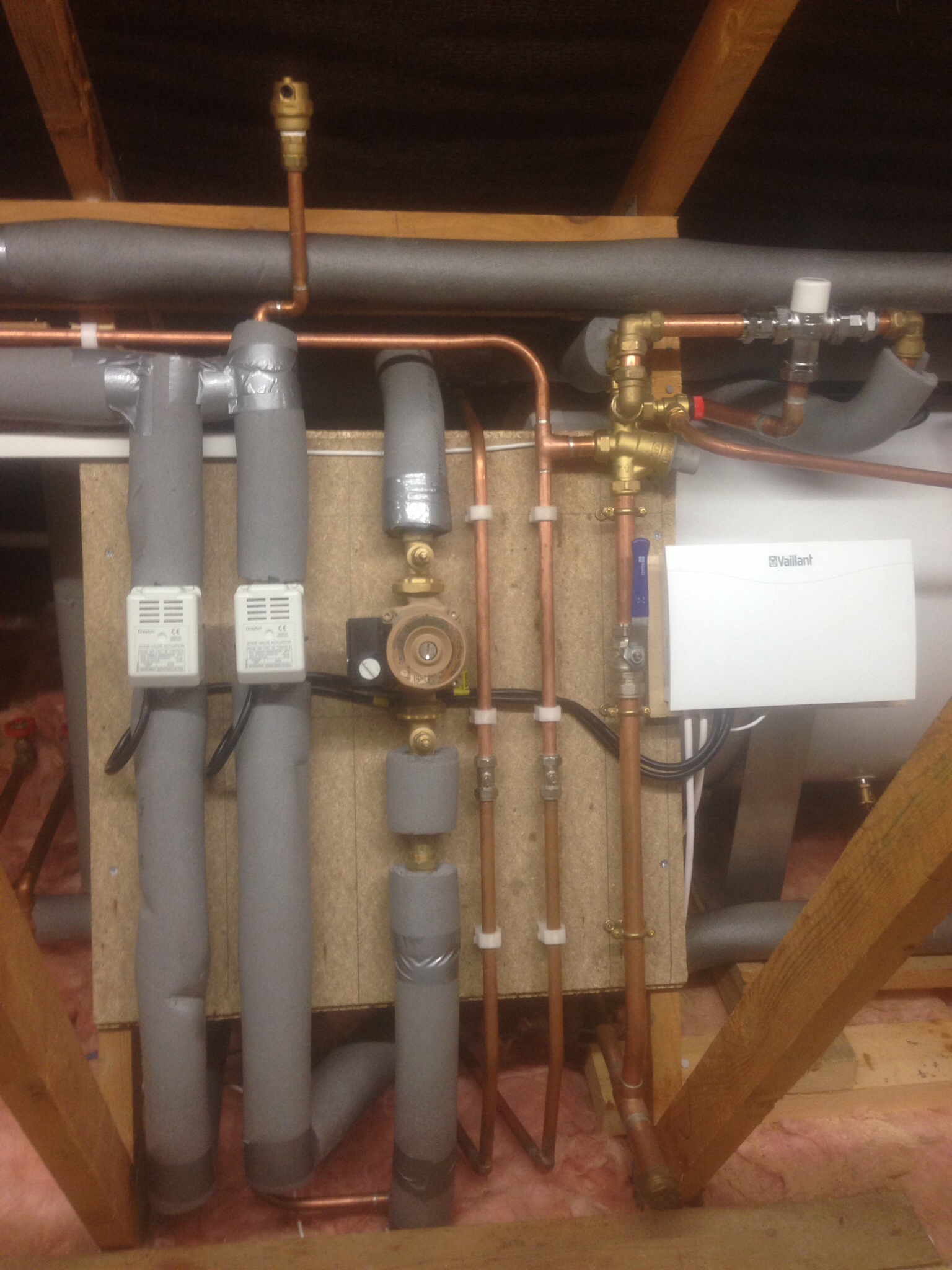
Yup, as long as there are actuators per loop that will close off flow. What this will do, is give 100% pump potential to the FF manifold, which is what we need for a practical test run. Defo needs a FLIR / IR thermometer so you can see the heat pushing through the pipes (or not). Sorry, that doesn’t answer my question. The loops need to be purged one by one with cold mains. If this didn’t happen then it needs to, if you’re looking to eliminate every possible reason why this isn’t working properly. My immediate gut feeling is that you should defo have had 2x manifolds, each with their own pumps, and each with a TMV; this would allow a higher flow temp to the FF UFH and for the GF to be dialled back accordingly. You have 2 very different emitters here, BUT, if well insulated/airtight/MVHR then the requisite heat for the FF should be minimal. I’m glad, as the install in the pic is 🐕 💩.
-
16mm pipes?
-
I’d firstly shut the GF UFH off by closing all the loops and see what happens to the FF. Best to just pull the band aid off and start there imho.
-
Oh lord. This is NOT a great way to install UFH…. They should have notched the tops of the joists, not dropped down and under! These are now all significant air traps, and as the water flows so very slowly any trapped air cannot escape by being pushed through by the pump. Did you witness the installer purging every single run one by one, with cold mains pressure to evacuate the air and ensure each loop was completely populated with water? This needs to have been done religiously.
-
Best approach at this exact moment, to see if what you have can be rescued. If the FF heating cannot get those rooms to 21°, without the help from the GF UFH, then it’s just not been installed well, eg with very little contact between the plates and the 22mm deck. I always staple the life out of these plates to have as much surface > surface contact as is possible, normally using an air powered or electric stapler. If there’s not much contact then the plates would need a big uplift in flow temp to compensate. Ive done installations with “J” plates, and they can work well, but not if the heat can’t transfer to the deck.
-
Sounds like a GF stat, so no separate stat for the FF, so this isn’t sympathetic at all to the two very different types of emitters.
-
This is a candidate for a low loss header or 4 port buffer imo. In most instances I’ll put a TS instead of an UVC, with the TS providing DHW, if it’s an oil boiler. I do this when there’s mixed temp heating or multiples of zones of heating, but always if there’s UFH. Is it possible to at least add a LLH here?
-
metal framed cupboard and dropped ceiling
Nickfromwales replied to Thorfun's topic in General Joinery
If you have various "attachments" required in the dungeon basement, then possibly yes. -
Can you post some wider aspect photos plz? Id say you need to tie in some masonry on the interior, and then screw the frames far better to arrest all that cracking. This simply doesn’t have anything to fix into so that needs to be done properly before sealing up again.
-
How big are the holes, Homer?
-
metal framed cupboard and dropped ceiling
Nickfromwales replied to Thorfun's topic in General Joinery
It’ll be the worlds smallest cinema room lol. 🤷♂️🤦♂️ -
Ah. Ok. Makes the 1st point moot then. My chap would have come out in the new year, but is due on site with us 17th next month, and is fully booked until the fat fella in the red suit attacks my wallet.
-
That’s for tape and joint, not for full wet plastering. Don’t use this.
-
metal framed cupboard and dropped ceiling
Nickfromwales replied to Thorfun's topic in General Joinery
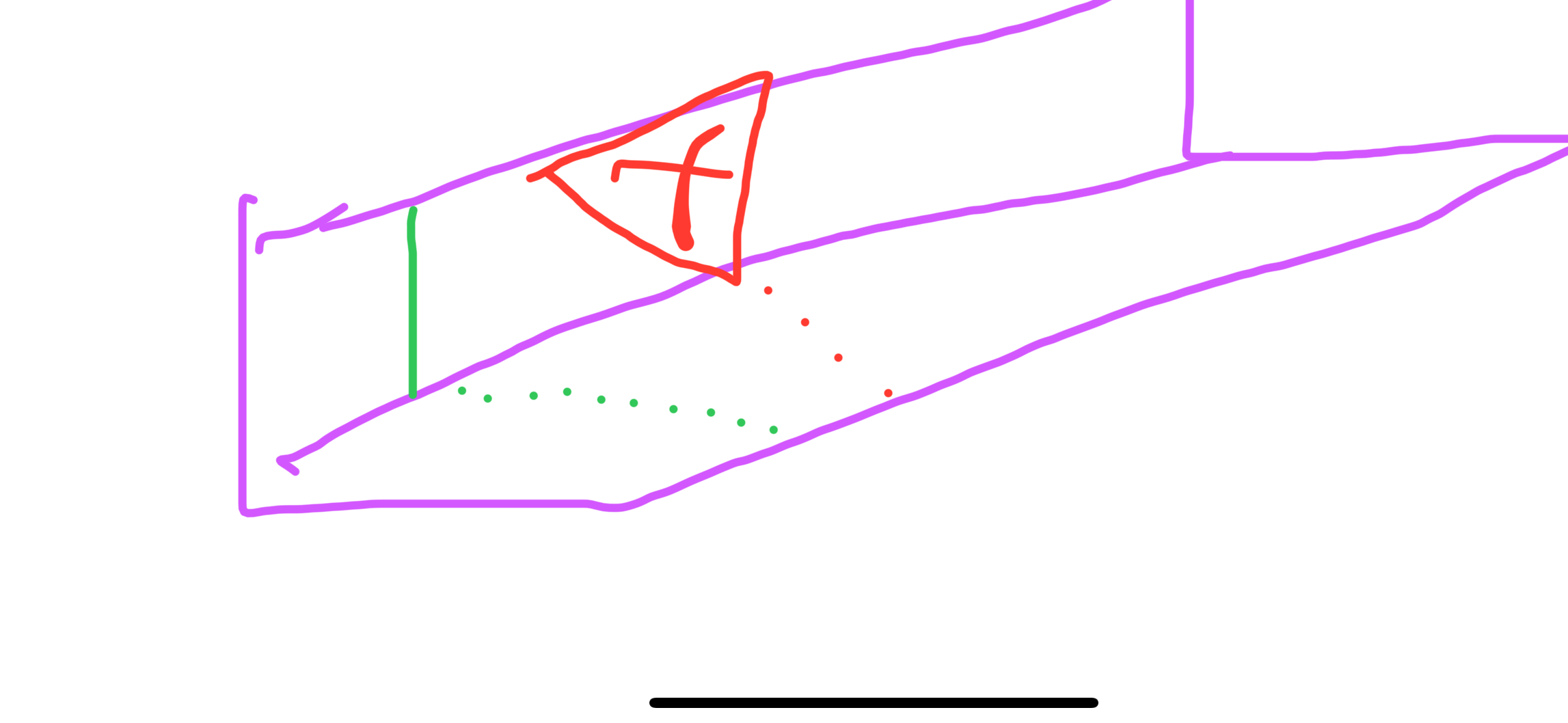
Get a bit of the wall / angle metal and cut about 100mm long. Cut out the red bit, bending along the red dotted line. Cut the green line, and bend that along the green dotted line by 90° to make an end return. Fix the bracket to the stairs sloping wall, then screw up through the flat section (that you don’t want to slope) into the tab created by the green fold. 3 of them, 2 of 200mm in from each side and one centred, will take out any twang. Red dotted line should have been parallel with the green one. Prob quicker if I fold 3 and post them to you lol.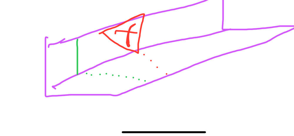
-
Snowman’s bone? lol. All you need is a good spread. Where about are you in the world?
-
metal framed cupboard and dropped ceiling
Nickfromwales replied to Thorfun's topic in General Joinery
You just cut small off cuts and snip the middle, to make little ‘angle-adjustable’ brackets, to hold this firm. Fit it horizontal / flat from the right hand wall to the wall that returns to the side of the stairs, then install 3 or 4 of your home made brackets to take any wiggle up. Quicker and easier than fecking about shaping wood. -
metal framed cupboard and dropped ceiling
Nickfromwales replied to Thorfun's topic in General Joinery
Everyone, “news flash!!”. It’s a tiny cupboard. -
metal framed cupboard and dropped ceiling
Nickfromwales replied to Thorfun's topic in General Joinery
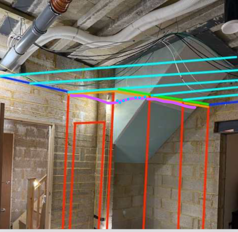
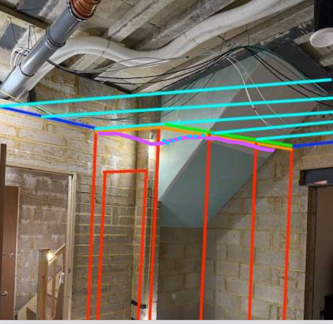
Those two walls will act as buttresses to themselves, so once boarded they would stand alone with ease. I would firstly fly the ceiling (cyan lines) into the z shaped wall, purple, so you have more structure meeting the staircase and side wall to the door.