Jump to content

Temporary heat source for UFH: Willis heaters


oranjeboom

26526 views

After various delays, the time has come to get some heat into the house, and as there have been a few on BH that have gone down the route of Willis, thought I would give it a go as well. Hopefully others will find the blog entry also.


Background:

  • Renovated (3G passiv-rated windows, 120mm EPS EWI, 400mm loft insul, MVHR - not tested air leakiness yet) / extended (175mm SIPs) south facing detached house, East Kent
  • 156sqm of wet UFH in 100mm concrete (with circa 300-375mm EPS insulation)
  • 130L in UFH
  • Wunda 12 port manifold (The heating valve on the manifold operates in the range of 30-70oC)
  • Wunda wired room thermostats for each room (but probably won't use for this temporary setup now)
  • 12Kw eDual for DHW (not to be included as part of Willis setup)
  • 12Kw Sunamp for DHW/UFH (not to be included as part of Willis setup)
  • 3.8Kw PV (potentially have further DIY grid implemented later on)


Not looking to cater for worst case low temps as at these times will just plug in some extra heaters:
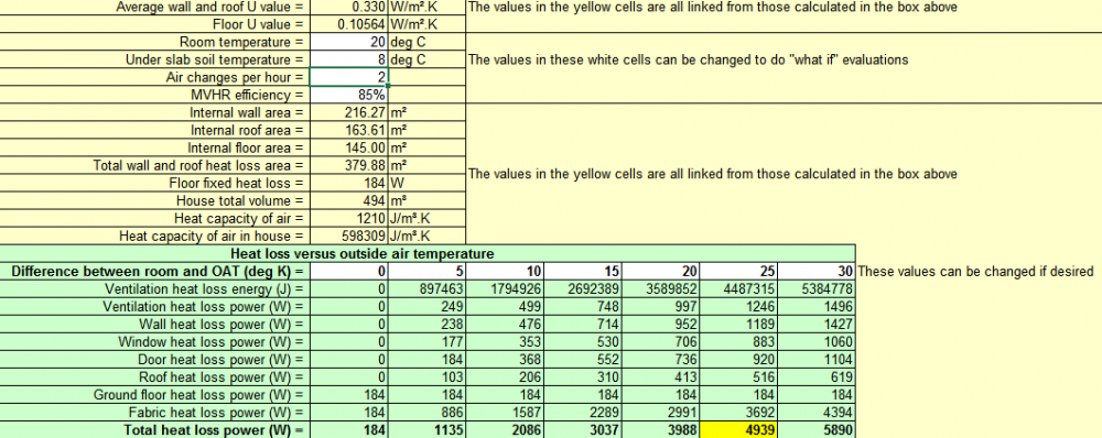
 

image.thumb.png.295847607acdac4392e32785661847d1.png


image.thumb.png.c4678aa7fe5231b1bb4fc06732888055.png


I originally ordered 2x 12Kw heat batteries for DHW and UFH. Total reliance on the PV in summer and then off-peak grid in the winter. An all electric approach initially without ASHP. Not keen to spend £8-10k on an MCS installed heat pump to get back an estimated / possible £8-10k. Installers seem very vague on the RHI returns and if I have read correctly, I will have to be metered in order to qualify in any case (as have not lived in the property previously). Since the house will be far above buildreg stds (but below PH level), I simply won't be using the amount of expected input that the installers calculate - hence I won't be getting back the cost of the ASHP supply and fit install. So most likely won't go down the MCS route, and if I were to install an ASHP, it would be a cheapy from fleabay.


Having excluded using an ASHP, I learnt that Sunamp were testing various units late 2019. But typically with Sunamp, after continued confusion on their part as to what ASHPs they may have tested/not tested/will be testing soon, I've made the decision that I can't want any longer on their input. So for now I will leave the ASHP option until later on and perhaps consider a propane unit (e.g. Vaillant ) when they come online on a non-RHI basis if I can get a decent install cost.


Willis Heater approach

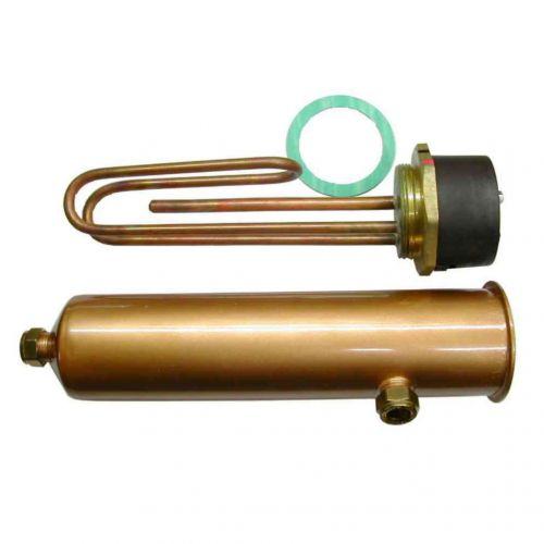
So therefore looking to heat the UFH with 2x 3Kw willis heaters in order to progress with the internal house work. Thought I'd add some info on here as a lot of people like myself aren't familiar what they are. They originated out of Ireland and still much in use over there. They're essentially external immersion coils and instead of sitting inside a tank are simple external electric units - AKA "Willis jacket", "standard sleeved immersion heater"," inline electric heater". Googling should get you something like this:

Willis Immersion Heater | Shell & 3kW Element


Item Weight 1.15 Kg
Product Dimensions

30 x 9 x 9 cm


I have tried to get plumbers interested in rigging this up, but they're either not interested or have told me it's not possible/don;t know what a willis heater is. I've managed to plumb in all the Hep2o in the house, so hopefully this won't be too much of a bodge.


@TerryE has kindly discussed his set up which is pretty impressive with his DS18B20s set into the walls etc. I'm no programmer and my javscript is mainly simple web stuff and wanting to get heat into the place ASAP, I just want a KISS approach for now. Perhaps later I will think about having some of it programmed using Terry's Node Red option which makes for interesting possibilities. Get a feel for Terry's approach here: 


But as I've said, I'm after a bog standard dummies approach to this - seriously KISS:


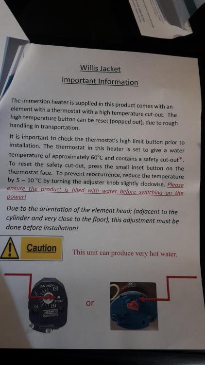
So rather than wiring up room thermostats to the wiring centre, I will for now simply use the Willis inbuilt thermostat and set that to gradual increasing temps from 10oC up to a max of 25oC. A gradual heat increase seems safer in my mind. My only concern is if the Willis thermostat fails and carries on beyond 25oC - up to max temp. Obviously I will have the manifold mixing/blending valve that should restrict temp flow into the UFH also, but is there a further failsafe to consider?


Dummies layout.

Eventual Sunamp units (for DHW) will be located on left of manifold so having to locate Willis heaters to right  and expansion vessel top right:


1909803810_willissetup2.JPG.ac25b07edcc1b69892d4d33a3c4e984b.JPG

FYI: The immersions need to be turned the other way (so colder water enters the side)


Parts list:

  • 15mm copper pipe. The Willis heaters are 15mm so I presume plumbing them into the manifold with 15mm would be okay?
  • 15mm plastic pipe for cold return should suffice I presume?
  • Bottle vents - automatically release any trapped air (like this one). Do I need any and if so where do I place them?
  • Willis heater (ebay has the cheapest)
  • Expansion vessel - 8litres sufficient for total UFH volume of 130L? (like this one
  • 20A DP switch outlet (for each willis) from a 16A MCB (like this one)  . Probably one for each willis
  • Immersion timer (like this one) to be added possibly when I change over to E7 low tarriff rates


Will get an electrician to wire it all in for me!


Be grateful for comments, suggestions and any answers to above questions!


FYI: I'm no way the first person to install a Willis, so here's a list of other users on BH that have gone the Willis way and will know more than I do:


@dpmiller: photo / details here

@TerryE

@vivienz

@CC45

@chrisb here

@Gav_P - here (Any pics?)


Willis instructions:


schematic


20200117_104153.thumb.jpg.1021a23b20f869bf8516fe2b44605ab9.jpg


  • Like 5

159 Comments


Recommended Comments


I can’t comment but a very interesting post and I too will be looking to have my set up as KISS as possible. 

Link to comment

Ok so use copper within 1m of the Willis just for ease. If you don’t want to do compression joints then use these as they are just as quick but can be de-mounted unlike the Sprint version ... you will also need a decent copper in pipe slice - this will last you a lifetime. 
 

Expansion vessel should be 15 litres, it’s not a stored system so don’t need to be looking at over pressure valves but I would add a pressure gauge and a fill loop and reduce the pressure in the expansion vessel to 1.5 bar as they are pre-charged at 3 bar. 
 

Rest looks fine - post up some pics and we can see where to help. 


Link to comment

You definitely need the PRV, but not the BV.  The Wunda manifold has a manual bleed which you can use to release any gas, but the system is closed so you won't get any gas build up.  You need to do you UFH routing but ~160 m2 of slab should work out at around 7-8 x 100m loops.  You want to balance you loops for even flow and keep the loops to just under 100m each or alternatively 75m if you are using 300m coils.  You must avoid any joins in the slab: each loop has to be one continuous length of pipe.


I note that given a wall U-value of 0.33 and your calcs seem off to me:  I can't understand why your floor and wall losses are of a similar order when you have 50% more wall and the U value is 3x worse.   You also seem to be planning far below a PH class house, so your house as a system is quite a bit different from mine in its operating nature.  I use the thermal capacity of the slab to advantage so pretty much all of our heating is done using E7 low tariff rates and we operate the house as a single zone.   You seem to be designing your 2 x Willis as a pretty much always on (during peak heating months) heat source.  Have you costed the running costs?  IMO, you've moved well into the zone where a more cost efficient heating method such as an ASHP or even gas should be considered as an option.  Something doesn't hang together here.


Edited by TerryE
Link to comment

@TerryE Thanks - UFH is all fitted. See my other blog entry on that fiasco! As for the calcs, I will have to re-examine those. The walls are a mixture of old school cavity insulated brick with EWI and then the extensions are SIPs, but will look at the figures and hopefully realise I've gone wrong somewhere.


@PeterW Thanks for the tectite tips. Yes, a bit lazy to use those, but used a few connectors like that for my plumbing manifold setup. Will also look for a bigger expansion vessel then.

Link to comment

I believe that it's best to fit the Willis heaters so that the immersion is at the bottom, rather than the top, so as to avoid getting an air pocket adjacent to the element that cannot be bled out.  Alternatively, they can probably be mounted on their sides, with the side pipe poking upwards.


I'm no expert, mind, it just seems more logical, and potentially a bit safer (in terms of avoiding overheating the small bit of element in the air pocket) if they are arranged like this.  It may be that the MIs say different, and MIs always trump any other advice.

  • Like 2
  • Thanks 1
Link to comment

^^ +1

Also top mounted immersion heaters are far more prone to tripping their safety thermostat, even when working normally.

Link to comment

I,m with @Jeremy Harris, the picture on the side (above)tho shows it mounted on its side with input pipe coming upwards but as JSH says it cannot be bled completely of air like that. Be interested to hear from someone that has fitted one and what it’s fitting instructions were.

Link to comment

The only issue I can see is getting enough flow from the willis into the manifold, it's certainly something I had to work with. The heat source generally has it's own pump pushing into the manifold...

The 'stat in the immersion has a fairly broad hysteresis. You'll probably have to go a fair bit higher than 25 to get it to stay on.

Likewise your mixer may not be incredibly sensitive.

Link to comment

So, just putting my final shopping list together:


Expansion vessel

On 07/01/2020 at 11:22, PeterW said:

Expansion vessel should be 15 litres, it’s not a stored system so don’t need to be looking at over pressure valves but I would add a pressure gauge and a fill loop and reduce the pressure in the expansion vessel to 1.5 bar as they are pre-charged at 3 bar. 


Can't find 15L, so oversizing it won't matter I assume? i.e. 18L expansion vessel (with loop and fixing kit).


Pressure relief valve

Only need the one correct, and that comes with the above expansion vessel kit?


Bottle vent (fix to manifold)


On 07/01/2020 at 11:45, TerryE said:

You definitely need the PRV, but not the BV.  The Wunda manifold has a manual bleed which you can use to release any gas, but the system is closed so you won't get any gas build up. 


Yes, kept on having to release air during initial loop fill up (pressurising for concrete pour), but was thinking to add a bottle vent to the manifold so that any air is released automatically. Manifold is not pressurised at the moment so will have to do that.


20A DP switch outlet (for each willis) from a 16A MCB (like this one)  . Probably one for each willis

Immersion timer (like this one) to be added possibly when I change over to E7 low tarriff rates

15mm copper pipe - Willis heater connections are both 15mm, so seems best to just connect it all with 15mm pipe, unless there's a reason not to?

Willis Heater - purchased


Link to comment

Expansion is fine oversize, you need a lower pressure valve so possibly want to find an alternate to the 3 bar one. 

Link to comment

I have a beginners question.


Is the dashed "mains fill" feed permanently connected at mains pressure to a t-connector at the base of the expansion vessel? I assume not because of the risk of inhibitor chemicals leaching back into mains fresh water.

Link to comment
1 minute ago, epsilonGreedy said:

I have a beginners question.


Is the dashed "mains fill" feed permanently connected at mains pressure to a t-connector at the base of the expansion vessel? I assume not because of the risk of inhibitor chemicals leaching back into mains fresh water.


The filling loop should be a flexible pipe, with hand disconnects and shut off valves at both ends, and a non-return valve on the mains feed side as well.  When not being used to fill the system the valves should be shut off and the pipe disconnected.  In practice the pipes are often left connected, with just the valves shut off for isolation.  You can buy a filling loop kit which has all the bits needed, like this one:  https://www.screwfix.com/p/r24-filling-loop/83905#_=p

Link to comment
56 minutes ago, Jeremy Harris said:

In practice the pipes are often left connected, with just the valves shut off for isolation. 


This is what we do.  The two valves are set to isolate the UFH circuit.

Link to comment
20 minutes ago, TerryE said:


This is what we do.  The two valves are set to isolate the UFH circuit.


I think it's what many do, but to comply with the regs there needs to be an air break between the mains and the inhibited water in the system, I believe.  This is the reason that the filling loop pipe has O ring seals and hand operated retaining nuts, so it can be removed when not in use (without tools) and so provide the required air break.

Link to comment

Updated setup. Others have the Willis with element at top, but I may 'lay' mine down to prevent air being blocked in top. Will see what the instructions say, if anything. Internet a bit scant on instructions so will post on here when I get the goods. Also added bottle vent to manifold and NRV on mains fill line. Apologies for the small print.


image.png.11e72a65124bc44e2d0672d86ee3f845.png

  • Like 1
Link to comment

The 20 A DP isolator needs to be uprated, or two need to be fitted, as each Willis heater will draw around 13 A, so with both on the current will exceed the 20 A rating.

Link to comment
5 minutes ago, Jeremy Harris said:

The 20 A DP isolator needs to be uprated, or two need to be fitted, as each Willis heater will draw around 13 A, so with both on the current will exceed the 20 A rating.

? Yup, I thought that was the case and had two on my shopping list above already. Will add it to the diagram for future refernce/readers! Thanks J!

Link to comment
9 hours ago, Jeremy Harris said:

but to comply with the regs there needs to be an air break between the mains and the inhibited water in the system, I believe.  This is the reason that the filling loop pipe has O ring seals and hand operated retaining nuts, so it can be removed when not in use (without tools) and so provide the required air break.


IMO, there really needs to a sensible balance of risk here. In practice for contamination to get back into the potable water line we would need 2 ball valves, one lock shield, one PRV and the mains pumps all to fail.  By comparison with the 737MAX MCAS implementation, the failure of a single mechanical sensor (which is perhaps at least 4-5 logs more likely) could lead to the deaths of ~200 innocent passengers and without the seeming prospect of criminal prosecution. 

Link to comment
1 minute ago, TerryE said:


IMO, there really needs to a sensible balance of risk here. In practice for contamination to get back into the potable water line we would need 2 ball valves, one lock shield, one PRV and the mains pumps all to fail.  By comparison with the 737MAX MCAS implementation, the failure of a single mechanical sensor (which is perhaps at least 4-5 logs more likely) could lead to the deaths of ~200 innocent passengers and without the seeming prospect of criminal prosecution. 


I agree, but I didn't draft the WRAS rules, I'm only repeating them here!


FWIW, I leave the fill loop pipe connected as well, as much to keep it tidy and the ends clean as anything else.

Link to comment

BTW totally off topic but this is very sobering viewing for those interested in flight critical SW failures:


Link to comment
On 13/01/2020 at 09:49, PeterW said:

Expansion is fine oversize, you need a lower pressure valve so possibly want to find an alternate to the 3 bar one. 


Ok, so pressure relief vessel kit came with 3bar pressure relief valve. What pressure valve should I be looking at and where to source one from. The ones at Screwfix etc all seem to be fixed at 3bar.


Currently have this one: https://www.altecnic.co.uk/images/products/info/313_314 Safety Relief_DS_07_11.pdf


They do have a 2.5 bar also, but is that going to make much of a difference?


https://www.altecnic.co.uk/domestic/plumbing-heating/sealed-systems/616/


Link to comment
On 13/01/2020 at 09:49, PeterW said:

Expansion is fine oversize, you need a lower pressure valve so possibly want to find an alternate to the 3 bar one. 

Why do you need a lower pressure PRV?  Which bit of the system can't take 3 bar?

Link to comment

No point in running 3 bar on a system that is just circulating water in the UFH. Lower pressure is less stress on joints etc, and as long as it’s above 1 bar then you won’t have any problems. 
 

I use standard copper cylinders as buffers too and they only take 1.5bar before they pop the domes on the bottom - another reason to have a low PRV

Link to comment

Create an account or sign in to comment

You need to be a member in order to leave a comment

Create an account

Sign up for a new account in our community. It's easy!

Register a new account

Sign in

Already have an account? Sign in here.

Sign In Now
×
×
  • Create New...