jfb
-
Posts
666 -
Joined
-
Last visited
Everything posted by jfb
-
What finish have you got on the breezeblock? if plasterboard you want that on first and then a bit of scrim tape joining the ceiling skim to the wall. Same if rendering.
-
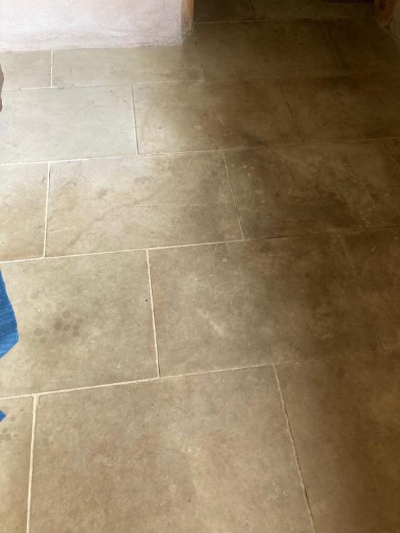
Anyone with some real world knowledge of sealing sandstone?! I bought a job lot of sandstone (think it was sold as yorkstone) that I suspect was really designed for outdoor use. Anyway I used it to finish off the downstairs of my house. I bought and applied a sealer recommended for such a job (can't remember which one exactly). It has never been very effective so 5 years later you can see dark areas where there has been traffic and the original colour where there hasn't. Never really had a go at cleaning it properly but after a bit of a go it looks like it should be possible. I don't want to clean the whole lot till I have a solution to sealing it successfully. Pretty sure the sealant I used was a water based , breathable type (though there is no need for it to be breathable since there is concrete/dpm below). Unlike the limestone floors on our kitchen where water will pool on top on the sandstone it darkens the colour of the stone and is absorbed at present so clearly not right. Anyone know what will work? Do non-water based sealants work better though with the issue of VOCs? Picture below shows what I'm dealing with - you can see the light corner where there is normally a table that has remained the original colour.
-
Oak beam versus steel/concrete lintel strength comparison
jfb replied to jfb's topic in RSJs, Lintels & Steelwork
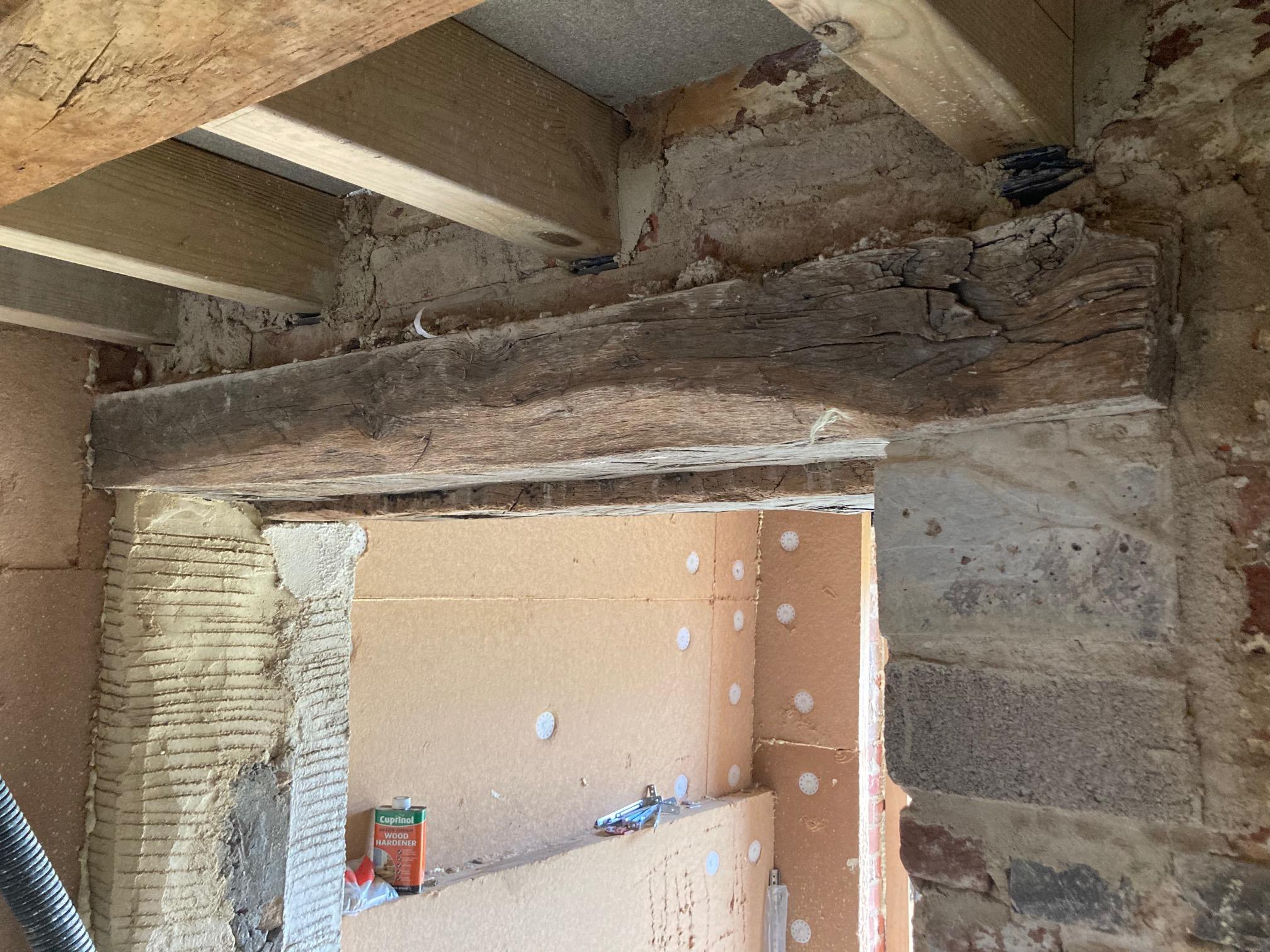
I have done that on one side of the opening. On the other side its a bit trickier to use concrete as I have joists to deal with hence why steels were suggested originally. But I'm hoping the engineer will ok it as is because it will be a pain to redo! Pic 1 is side with concrete and pic 2 is without.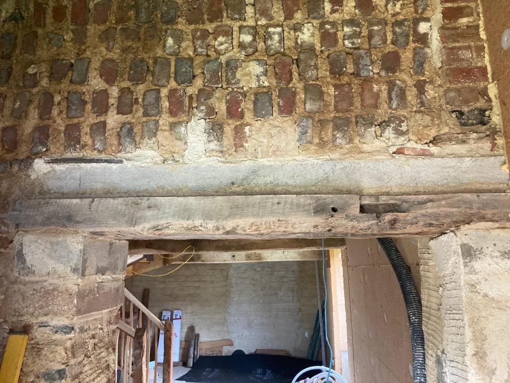

-
What the …. is the point of the MCS if they aren’t able to provide sensible guidance when needed? And then the fact that none of the MCS installers know what is going on. Madness.
-
Does anyone know of the comparative strengths of steel beam/reinforced concrete lintel versus oak beam for an above doorway lintel application? Engineer specified a 2N 152 x 152 x 23kg UC or 3N 100 x 140dp precast concrete lintel I have a seasoned oak beam that is 160 x 130 and would like to know if it is comparable. I have the engineer coming back at the weekend to go through it but I would like to be well informed. Anyone know of any resources out there as I can't find any? Lintels are 1.4m
-
great - ill take a good look later and try and digest it all!
-
Can i ask do you have a schematic of your set up LA? Specifically how you circumvent the LLH? Does your set up have 2 zones (UFH and rads?) or something else? I have a manifold downstairs for the UFH and the cylinder upstairs. Where is the ideal position for a buffer - next to the cylinder or the manifold? Regarding buffer - I asked before but can anyone say what size minimum I could use? For reference it is a small 2 bed, 70m2 area internal, downstairs about 40m2 of UFH pipes at 100mm centres. LA - was it installed so as to get the BUS grant or old RHI? As in did it have to be signed off by someone to qualify? I ask because I imagine I might have issues getting Alto to sign off if I start circumventing the LLH. Again sorry for all the questions and thanks for any replies!
-
Again I'd like to thank everyone's contribution to the thread - I am not trying to encourage disharmony and bitterness! I have a package already arrived and waiting to install so I have to make do with what I have. Despite the limitations of pre plumbed cylinders that are not so obvious to the lay person Peter there are some advantages. Total cost of parts is around £4.8k and the reality for me is that if I had gone down the non pre plumbed cylinder I would be charged £750 more from my plumber and an unknown amount more from the electrician (and less confidence that it will all just work). Maybe one can get the cylinder itself a lot cheaper but that wasn't the case through Alto. Anyway I am not really interested in more discussion about this side of things I am just after practical solutions so I will fire off a few more questions.
-
Is that the sort of size a buffer should be or can it be a lot smaller? Not sure I have much room for more cylinders!
-
I like the sound of this but I am worried that there is a bit more to it as Peter has alluded to, including electrical connections and valves, etc
-
150mm polished concrete slab with UFH pipes downstairs. Was presuming it would just be the UFH that I would be cooling though I take your point about upstairs being more desirable to cool in some ways. Too late for UFH upstairs as I am a fair way towards completion!
-

-
-
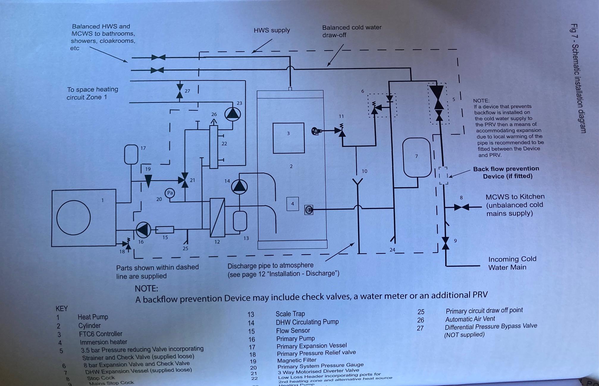
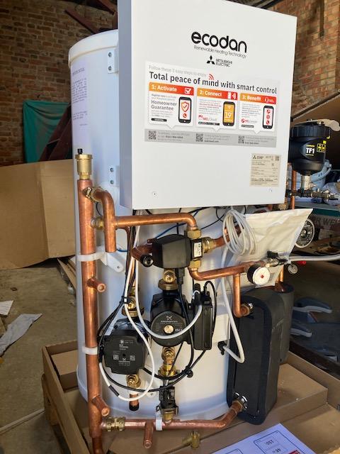
Firstly, I really appreciate everyone's input - thanks. I have to say I am a little lost when it comes to the intricacies of all this - I couldn't tell you without looking it up the difference between an S and Y plan for example so bear with me! It is from Alto as you all seem to know. It has finally arrived after a long wait and I will have got a recommended plumber ready to install it. I am not fully confident that left to their own devices the plumber and electrician will install it to allow for cooling and so I would like to have a solid understanding of the necessary steps needed to succeed. It is a 150l pre-plumbed standard cylinder EHPT15X-UKHDW that accompanies the 6KW Ecodan and FTC6 controller. I have 4 UFH loops downstairs that will be one zone and radiators upstairs as a second zone that are sized for low temperature so can run at the same temperature as the UFH (I assume that is the case as it is well insulated, airtight with MVHR and initially I considered not having rads upstairs but have them partly because without them I wouldn't be eligible for the new £5k grant). Currently no PV or plans to do so. I can't quite grasp the mid-position v. diverter issue and how it relates to S or Y plans (is S/Y plan another one!?). From what I can gather the schematic they suggest is a Y plan (the 3 port being the Y) but you are suggesting that S is needed for cooling. By mid-position are you referring to the Y plan and for S plan I need the diverter valves? One thing I don't know - is the low loss header something not likely to be included in the kit (I can't see one) and so the choice of LLH or buffer is still open. Looking at the diagram in the manual for cylinder it seems to specify a LLH (number 22 in the picture below). I am slightly worried once I suggest the buffer alternative that Alto will say that isn't what Mitsubishi specify so they can't recommend it/sign it off. I'll attach a couple of pics of the cylinder down below as well.
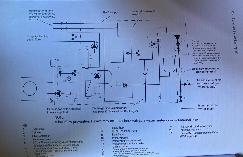
-
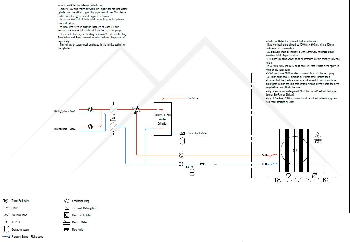
As the title suggests - would this schematic specified for an Ecodan PUZ-WM 6kw ASHP and pre plumbed cylinder with an FTC6 controller work for cooling? I seem to remember reading past posts that suggest something different needs to be done (is it to isolate the cylinder when working in reverse?). A further point - I know that some think 3 port valves the work of the devil! Why is that and what is the alternative? Thanks for any advice.

-
It’s for a small dwelling with 11 circuits (so far!)
-
Anyone got any recommendations/preferences for good quality CU? my electrician used to use MK but says quality has gone down and are looking at contactum though I had less good experience with them a while back (before the days of all metal). I have liked hager .
-
I don't see the point of adding anything to a lime render - it is going to set fine. You could also consider just getting some hydraulic lime and sand separately as it tends to be a lot cheaper. But if it is just a small section may be easier to go for the premixed bags.
-
Hydraulic lime (which is what you want to be using, not hydrated) already sets in damp conditions. In fact it is best if it does not dry out too quickly which is why when you are working with hydraulic lime you should always damp down the render/mortar on days after applying it. It is the chemical reaction with the water that makes it set hard. So I wouldn't see any need to add pozzolans to the lime. Rendering with lime is not really any different to rendering with cement (except plasterers who aren't used to it might say otherwise) - you just have to make sure the walls are well damped down before application (especially in summer now) and are kept damp for a while after (you can spray it once a day).
-
Hadn't thought about this though I am hoping to get away without it since the isolator for the ASHP will be very close to the wall penetration so I presume I can get away with some suitable conduit.
-
I am installing a 6KW ecodan PUZ ASHP. Looking to 1st fix the main cable to the ASHP. It is a run of about 12m with insulation on one side of cable only. In the manual it says it says 'Outdoor unit input capacity Main switch (Breaker)' as 16 A and minimum 3 x 2.5mm cable. Does that mean the earth needs to be 2.5mm? (assuming it is one of the 3 cores) Part of me thinks I should just put in a 4mm cable but I don't want to over specify unnecessarily. Any one got an opinion?
-
Stud wall sound insulation question
jfb replied to jfb's topic in General Self Build & DIY Discussion
I’ve ended up using some left over air tightness tape around the sockets. Has to be better than nothing. presumably it is the airborne transmission of sound this is dealing with mostly. -
Stud wall sound insulation question
jfb replied to jfb's topic in General Self Build & DIY Discussion
interesting - hadn't come across that. presumably you mean something like this: https://www.insulationexpress.co.uk/speedline-acoustic-putty-pads though I can't seem to find it in smaller quantities. -
I have a 70mm thick stud wall to insulate for sound. I also have a lot of 75mm rockwool sound insulation. Is it better from a sound point of view to just fit the whole 75mm in or I could easily cut in half for 37.5mm thick with an airgap? I seem to remember it is best to have an air gap and if I slice in half it will go twice as far. Presumably 50mm with a 20mm gap would be best but trying to work best with what I have.
-
thanks all. Just had electrician who will be signing off round and he explained things nicely. Its all going to be easier than I thought!