gravelld
-
Posts
526 -
Joined
-
Last visited
Everything posted by gravelld
-

is it difficult to borrow if you have a deposit
gravelld replied to Amateur bob's topic in Self Build Mortgages
Normally you have to prove you have some sort of income stream. Depends what you mean by "self employed". If you mean _really_ self employed, i.e. sole trader then you have to show proof of your income into bank accounts. If you mean a company director then you have to show company accounts, proofs of dividends etc. -
Extractor not staying on (on lighting circuit)
gravelld replied to gravelld's topic in Electrics - Kitchen & Bathroom
Thanks so much, I'll purchase the kit this week and hopefully fit next weekend. -
Extractor not staying on (on lighting circuit)
gravelld replied to gravelld's topic in Electrics - Kitchen & Bathroom
All the lights in this room are low voltage fed from an appropriate transformer, but what about the light switch? Thanks for the heads up. -
Extractor not staying on (on lighting circuit)
gravelld replied to gravelld's topic in Electrics - Kitchen & Bathroom
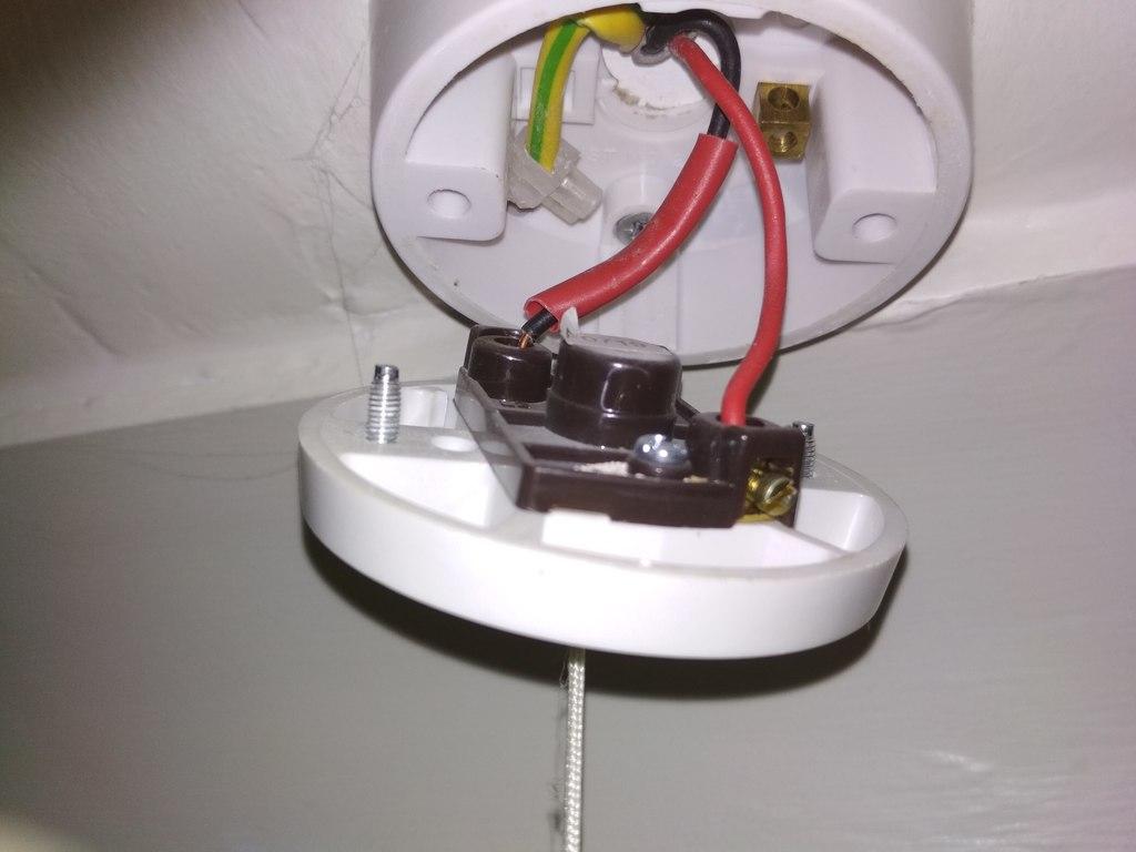
Ok, another step forward, I girded my loins and ran these tests. The bottom and right terminals give 240v. The top and right terminals, with the switch off, give 15v (! not sure if this was the multimeter) The top and right terminals, with the switch on, give 240v Thanks so much for taking the time to label those. It turns out you are one step ahead even on the identification of the cable. The cable you have labelled "power in?" was, I thought, the switch cable. It turns out it was a switch cable, connected as in my previous photos, but to a different switch in the original part of the house (maybe this explains the older wiring). The cable you labelled "To switch" is indeed to the switch I pictured above, in the same room as the fan. Do the test results above confirm the lower terminal? -
Extractor not staying on (on lighting circuit)
gravelld replied to gravelld's topic in Electrics - Kitchen & Bathroom
Yes - good point. It's going to a light fitting. Yeah, the cable from the switch junction box (this is what I will call the "switch cable") is the one at the lower right. There are two cables coming in here - the switch cable and... another one which I haven't traced. However the black conductor does not lead to the terminal at the top, it leads to the terminal on the right. The red conductor leads to the bottom terminal. I'm not that comfortable using a multimeter on a live circuit but I happened to have a voltage detector easily to hand so I tested for a current with that - it shows all cables into the bottom left and right of the junction box (so those from the switch and from the extractor fan are carrying current (with the light switched off). Let me know if I need more info. -
Extractor not staying on (on lighting circuit)
gravelld replied to gravelld's topic in Electrics - Kitchen & Bathroom
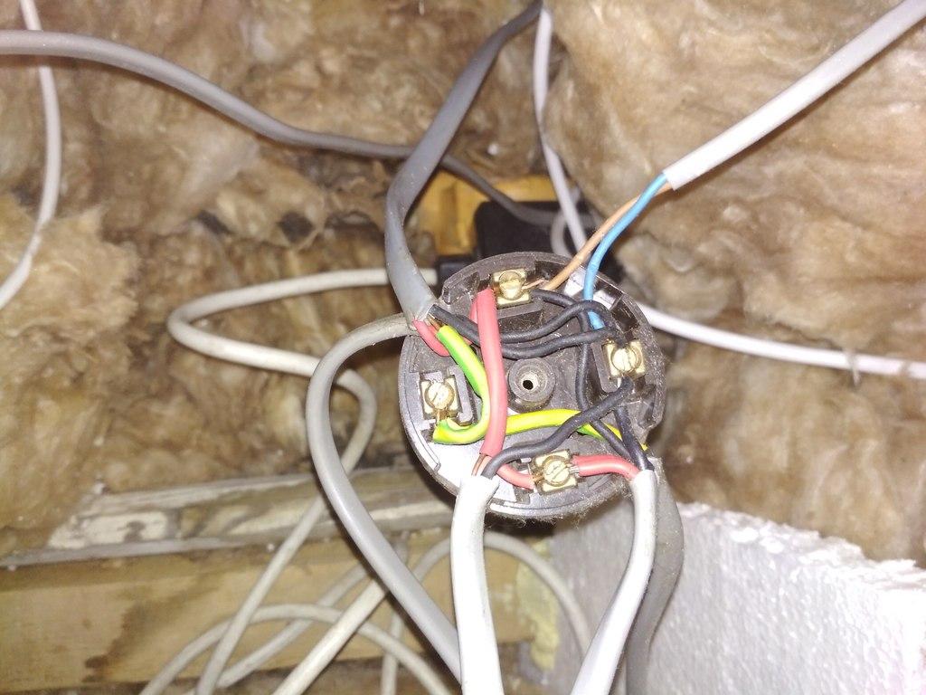
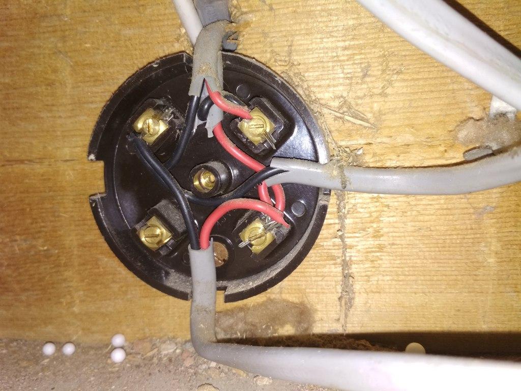
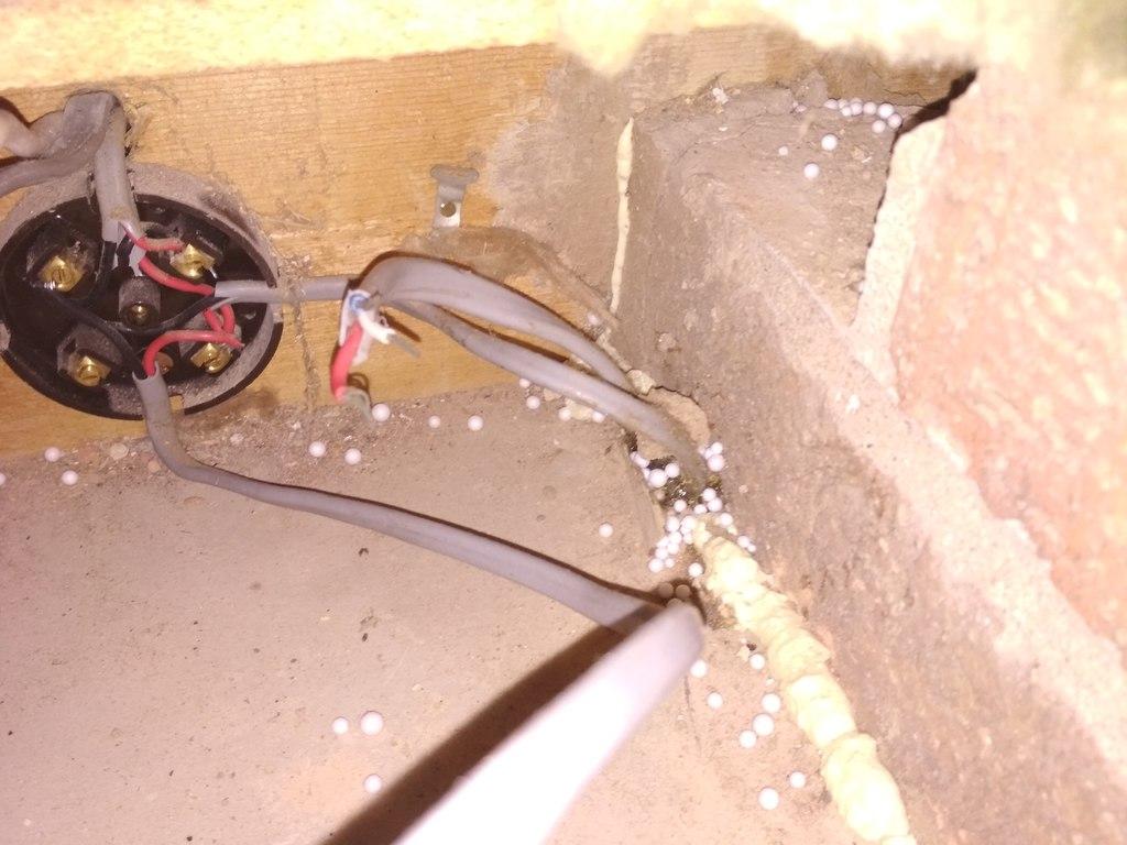
Ok, just got the chance to trace the wiring. The fan runs into the following junction box: The cable (I'm calling it that because it's stiff, maybe it should be correctly called flex) is the bottom-left cable. The lighter coloured cable to the fore at the bottom right then runs toward the light switch and into this junction box: The cable running into this box from the previous junction box is the one at the bottom. The cable to the right is the one that runs to the light switch. But before I show you that, there's another cable with a different colour code, coming from the ceiling in the general area of the light switch (but not actually visible in the light switch): The cable I'm talking about is the snipped one with blue, red and white coloured insulation. You can see it disappearing into the ceiling. Not shown on the other side of the junction box is a cable with the same colour codes. You can also see the cable from the junction box disappearing into the ceiling to the light switch. To clarify, the junction box you see above is the same one as the previous photo. Finally, the light switch: Are there any obvious strategies from here, do I need to do some more digging?


-
Extractor not staying on (on lighting circuit)
gravelld replied to gravelld's topic in Electrics - Kitchen & Bathroom
Thanks, I'll be back in the loft asap! Out of interest and to further my understanding, how dangerous was the initial wiring? -
Extractor not staying on (on lighting circuit)
gravelld replied to gravelld's topic in Electrics - Kitchen & Bathroom
Thanks, looks like I've got a lot more studying to do. Do you mean a switched line, i.e. are you saying only a switched live is present, with no permanent? How can I tell if the junction box has a permanent live? And if there's no such cable, I work back towards the switch? Bearing in mind this is old fashioned colour codes... -
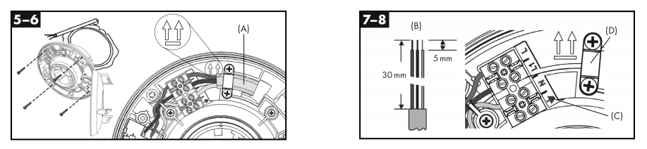
Looks like I'm in over my head again... I purchased one of these: https://www.greenwood.co.uk/product/153/unity-cv2gip to replace an existing extractor fan. I wanted this new unit as apparently it can run in trickle mode then boost when humidity gets too high. The old extractor just worked when the light was on, then had a variable overrun. According to this: https://www.amazon.co.uk/ask/questions/Tx25QNH37J3GAUG/ref=ask_ql_ql_al_hza the new fan should run when the lights are off. I simply rewired from the old extractor to the new one. First time, red into L, black into L1, unsheathed earth into N. I turned the power back on at the fusebox, with the light switch off... The fan turned on as I would expect, but the LEDs either side (coming off the same junction box) also 'glowed' on and off (other LEDs in the room were unaffected). If I turned the light switch on the fan turned off, and the LEDs turned on fully. So - oh dear - not really understanding what I was doing I rewired so black into L, red into L1, unsheathed earth into N. Now, with the light switch off, everything was off. With the light switch on, all lights turn on properly and the fan starts up. However, the fan stops when the light switch is turned off. Which is no good, as per the above requirements. It extracts at the trickle rate when the light is on. Before I check with the manufacturer I wanted to check I wasn't doing something silly with the wiring... or is the junction box setup somehow an issue? The LEDs use transformers to make them low voltage. CV2_Installation_Instructions.pdf
-
@joe90 well done, whichever way you look at it you have a high quality build.
-
That's why I don't like PIV.
-
Yeah they all mulch, so best not to have it too long I guess. A week is about the maximum on our lawn before I have to switch from mulching to bagging. But I find mulching is always preferable long term for the lawn, if you can.
-
New build energy efficiency "must haves"
gravelld replied to Olly P's topic in New House & Self Build Design
If you're talking log burners then that's another area you should research thoroughly (if efficiency is your aim). The trouble with log burners is what they are doing when they aren't running. If you have a standard open flued burner it's basically exhausting heat out of your house on a 24/7 basis. So instead you need a room sealed log burner. I believe there are some certifications around these about retaining their seals over many years use. You will need to run a duct to connect the log burner to the outside. Someone else will be able to fill you in on more detail with these. -
Another government debacle! 'smart meters'!
gravelld replied to oranjeboom's topic in General Self Build & DIY Discussion
So doesn't the question become - why aren't the suppliers paying for this reduction in their risk? Why are customers paying for them (through levies on everyone's bills)? Why was the "green crap" levy removed, but the "energy company CEOs' bonus crap" retained? -
Another government debacle! 'smart meters'!
gravelld replied to oranjeboom's topic in General Self Build & DIY Discussion
Actually, I've noticed in the marketing a recent downplaying of this. The adverts now start with "It won't fix climate change but...". Smart meters join the long and inglorious queue of silver bullets, alongside heat pumps, district heating systems etc. Eventually someone will work it out that we just need to build (and refurb) better. Much better. -
Would like to know solutions for this. I noticed one of mine has a cracked plastic layer over the sensor, and some of the plastic has dropped out. I would've thought this increases the sensitivity?
-
You would have to have immensely cocked up not to pass building regs. Our old draughty house is 5.8 m3/m2/hr and that is a representative hole of 1000 cm2. But I'm sure you have loftier goals. My comment about plasterboard etc was about - can you get to where the holes are *at the airtight layer* to fix them if you find them?
-
I meant things like - is this just a shell with the AT layer complete - is plasterboard up covering the AT layer etc?
-
If it wasn't so warm I'd say hire an IR camera... Something like https://www.amazon.com/Zero-Toys-Wizard-Stick/dp/B000FIN0V8 ? It might depend a bit on how performant the house is. You can quite easily feel the air movement in a normal build (although IIRC you are aiming higher). Are the possible leakage points covered? Also, what sort of tester is this - a one hour give-you-a-number-and-go type or someone that's going to stick around and help?
-
New build energy efficiency "must haves"
gravelld replied to Olly P's topic in New House & Self Build Design
No systems or bling, just fabric first - highly insulated, best windows you can afford, low air permeability. If you get that right then I'll grant you the MVHR bling ? But you probably won't need much in the way of heating, so a GSHP might be overkill. You're better off putting the £20k-odd that costs into the fabric. All completely possible with traditional design. -
When I visited one of my prospective window suppliers I parked up next to a skip full of crushed but still clearly high quality windows. I asked the installer about them; he said nonchalantly "oh yeah, the customer decided they didn't like the colour". I would've thought such wastage was good for business (if not the productivity of the economy at large) but it did make me wonder whether bargains may be out there.
-
Why don't you just use mechanical timers for the immersion heaters?
-
@nod what finish is your wall - what is the colour of the finish? Looks nice. And the ramp looks fun.
-
We pay: 10% deposit 40% 7 days before manufacture 40% 7 days before delivery 10% 7 days after delivery Nordan.
-
Location and type of airtight barrier
gravelld replied to davidc's topic in General Construction Issues
Well, more complicated answer is it depends on the insulant and the characteristics of the barrier(s) in terms of air and vapour tightness but the default is to have the air tightness inbound because it's more tolerant of the choice of materials (which may often be swapped on site etc).