John Carroll
-
Posts
552 -
Joined
-
Last visited
-
Days Won
3
Everything posted by John Carroll
-
Boiler short cycling with low flow temperatures
John Carroll replied to seanblee's topic in Central Heating (Radiators)
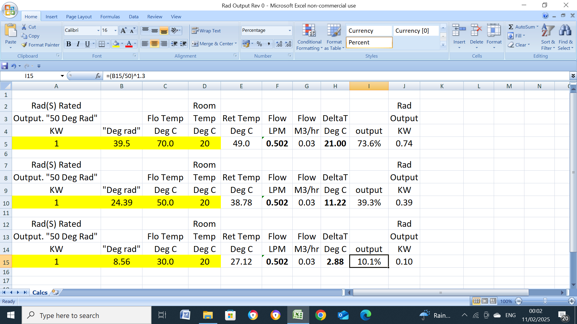
Is this a heatgeek table, if so, or whoever, then they must be changing the flowrate to get those sort of dTs?. If you use the third row, 70C/49C/21C, as the base, this gives a flowrate of 0.502LPM/kW and (assuming the same flowrate) a dT of 11.22C (vs 15.0C) at 50C flowtemp and a dT of 2.88C (vs 9.0C) at 30C flowtemp. (Assuming a 20C Room Temp)
-
Unvented Expansion Vessel Pre Charge
John Carroll replied to Mattg4321's topic in Boilers & Hot Water Tanks
What is the length and diameter of the connecting piping between the EV and the UVC. -
Unvented Expansion Vessel Pre Charge
John Carroll replied to Mattg4321's topic in Boilers & Hot Water Tanks
The EV will normally be sized to 10% of the UVC capicity, say 24L for a 250L UVC. If the precharge pressure is 2.8bar, the final pressure after heating to 60C will be 3.86bar and the EV will contain 5.25L of water, when the dynamic pressure falls to anything below 2.8bar then 5.25L of water will flow out of the EV when HW is drawn off, when HW demand ceases, 1.2L of cold water will flow back into the EV to pressurize it to 3.0bar, after a (if) full reheat, a further 4.05L will enter the EV to give a total of 5.25L. With a precharge pressure of 1.5bar those numbers will be 4.48bar after heating with 13.1L in the EV most of which will flow back out on HW demand, and 9.0L flowing back in on HW demand ceasing plus a further 4.05L after reheating to give that total of 13.1L. 0.6bar precharge gives, respectively, 5.92bar final pressure with 18.45L in the EV, most of which will flow out on HW demand, 14.4L will flow back in on HW demand ceasing plus a further 4.05L after reheating to give that total of 18.45L. You can see there is far more water being shunted back and forth the lower the precharge pressure is, the EV is then actling more and more as a accumulator which may or may not be benificial, with a very low precharge of 0.6bar, the final pressure is quite high at 5.92bar, but OK at 4.48bar with a precharge of 1.5bar. The loud gurgling migh be the combination of a low precharge pressure with a small diameter connecting pipe between the EV and the cold feed. -
You could/may still have a air bubble in the Megaflo in which the water level will rise & fall a bit especially with fluctuating dynamic pressure which can cause movement/noise of (if) broken baffle bits. If you remove the HW outlet pipe it should be relatively easy to drill even a pin hole sized hole in the dip tube which will very quickly destroy the air bubble, you then have a full cylinder of water with virtually no movement as it will all happen in the EV and just might stop that noise.
-
Expansion Vessel losing pressure... but where from?
John Carroll replied to MJNewton's topic in Boilers & Hot Water Tanks
Suggest removing the plastic cap over the schrader valve and spray some soapy water all round the valve, these sometimes leak where they exit from the cylinder itself. -
Willis heater UFH. Heaters in parallel or series?
John Carroll replied to Russdl's topic in Underfloor Heating
The flowrate is somewhere between 0.1M3/hr & 0.2M3/hr, assume 0.15M3/hr, One heater ON, split flow, the dT is, 3.0*860/(0.15/2*16.66*60), 34.4C, assuming heater output temp at 38C (stat not tripping at ~ 40C) then the inlet temp must be a impossible 3.6C, or else stat not tripping and outlet temp ~ 59.4C (from inlet temp of 25C), mixed with the other heater outlet at 25C gives a outlet temp of 42.2C. If the flow, for one reason or other is all through one heater then the dT is 17.2C to give the same 42.2C outlet temp and stat probably not reaching cut out. I gave some advice a few years ago in the installation of a Willis (gravity circulation) heater to a HW cylinder with Iboost from solar PV and the only way it could be got to work was to use the Willis stat in a supervisory role and use a pipestat to do the switching because the Willis stat would not switch until around 75C, probably due to very slow circulation despite using 22mm piping, its still working fine. -
Willis heater UFH. Heaters in parallel or series?
John Carroll replied to Russdl's topic in Underfloor Heating
Doctor Willis will be delighted if his heaters are working as designed, ie convection only!. 12mm ID piping allowing ~ 60M/loop will have a friction loss of around 0.19M @ 1.0LPM, 0.4M @ 1.5LPM, and 0.68M @ 2.0LPM. Maybe increase the pump head temporarily to say 2.5M or even 3.0m (as long as you don't run out of power), note the flowrate, the % error will then be less, and the flowrate at 0.7M will be the sqroot of (0.7/2.5) or sqroot of (0.7/3.0) X the indicated flowrate. -
TRVs not responding to room temperature
John Carroll replied to Little Clanger's topic in Central Heating (Radiators)
Got the new EPH TRV, its indexed 0 to 5. At a OAT of 7C and leaving the TRV outside for a hour or so, I only have to decrease the setting to 4.0 when the actuator then contacts the push pin. Inside, after allowing it to heat soak for another hour or so, the push pin starts to move immediately on turning the actuator from index 5 (max). At setting 2.5 (which gives me ~ 18C), the valve is only ~ 1.5MM off its (closed) seat at a temperature of 15C or so. -
Willis heater UFH. Heaters in parallel or series?
John Carroll replied to Russdl's topic in Underfloor Heating
A excellent choice and a lovely pump, IMO!!, I have a 5 year old 6M version (no flow display) in a oil fired conventional rad sytstem, these pumps, as you are no doubt aware, can have the head incrementally changed in 0.1M steps in both CP and PP modes, to a min 0.5M minimum (on mine anyhow) and yes, just tried mine, it does display 2W at 0.5M in CP (and) PP mode. Even so, you must be circulating something through your system, would expect at least 0.5Ms/hr, say 8.0LPM, ~ 5W or more. What is the pump flowrate showing??.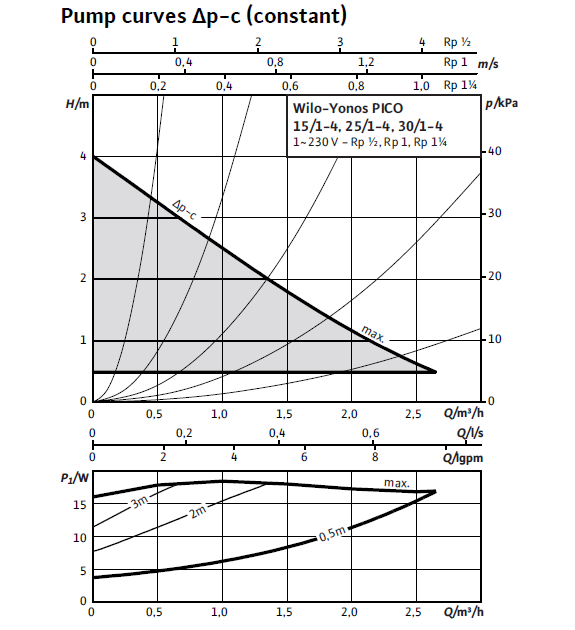
-
Willis heater UFH. Heaters in parallel or series?
John Carroll replied to Russdl's topic in Underfloor Heating
What make/model of pump do you have MIke and what mode/setting is it on, where are you reading the 2W?, I really can't see it pumping anything at that minuscule power, any A rated pump I've come across will require at least a closed valve 4W at the lowest setting, if you can get a accurate reading then the pump curves will give very accurate indication of the circulation rate, most A rated pumps now not only display the pump power in Watts but also the flowrate in M3/hr, very useful. -
Willis heater UFH. Heaters in parallel or series?
John Carroll replied to Russdl's topic in Underfloor Heating
kw is a unit of power, a gas boiler might have a output of say 25 kw (my upper/lower case sense of "kw" might be incorrect but doesn't matter from a thermodynamic point of view) so you have a 25 kw Boiler, etc. -
Willis heater UFH. Heaters in parallel or series?
John Carroll replied to Russdl's topic in Underfloor Heating
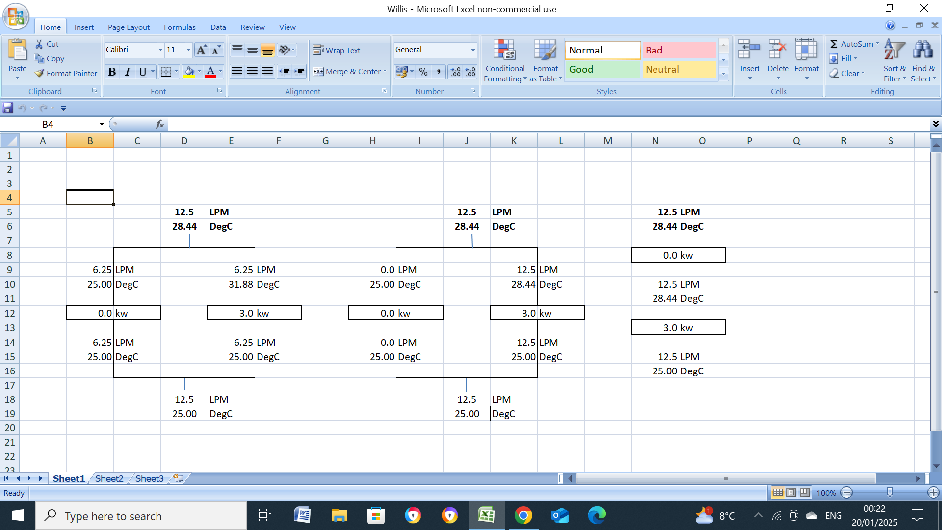
My maths?. I've allways used kw = (flowrate (LPM) x 60 x temperature rise, dT (deg.C)/860 so, kw = LPM*60*dT/860 or any variation of this once you know two of the values I used a total flowrate of 12.5LPM and 2 X 3kw heaters. From the above, kw = LPM*60*dT/860 dT = kw*860/60/LPM One 3kw heater, with a flowrate of 6.25LPM (12.5/2), will give a temperature rise, dT, of, 3.0*860/60/6.25, 6.88C, if the heater inlet temp is 25C, then the outlet temp is, 25+6.88, 31.88C, two heaters (on) in parallel will give a flowrate of, 2*6.25, 12.5LPM at the same dT of 6.88C with the same outlet temp of 31.88C. Two heaters in parallel with one switched OFF will give a 0.0C, dT , the other (ON) will give a dT of the above 6.88C. You now have 6.25LPM at 25C mixing with 6.25LPM at 31.88C. Let Tm = mixed temperature So, 12.5*Tm = (6.25*25)+(6.25*31.88) So 12.5*Tm = 156.25+199.25, 355.5 Tm = 355.5/12.5, 28.44C If one heater is OFF and the water flow through it shut off then 12.5LPM is flowing through the switched ON heater with a dT (kw*860/60/12.5) of 3*860/60/12.5, 3.44C, to give a outlet temp of, 25C+3.44C, 28.44C, the same as the above with the flow split between the two heaters. Two heaters in series, both ON, flowrate 12.5LPM. dT in both/either heaters will be, (kw*860/60/LPM), 3*860/60/12.5, 3.44C, outlet temp from bottom heater, 25C+3/44C, 28.44C, outlet temp from top heater, 28.44C+3.44C, 31.88C (same as with both parallel heaters ON, above) Two in series, one off, one ON, dT through ON heater, (kw*860/60/LPM), 3*860/60/12.5, 3.44C, outlet temp, 25C+3.44C, 28.44C, dT through top (OFF) heater 0C, outlet temp, 28.44C. (same as with one heater only on in parallel). You have ~ 800M of UFH piping, a loop might consist of up to 100M of piping with a flowrate of 2.0LPM giving say 6C to 8C dT at a flow temp of ~ 40c/45C, so each loop (assuming a dT of 7C) will emit, (LPM*60*dT/860), 2.0*60*7/860), 0.977kw, say 1.0kw, you should have ~ 8 loops so, at least 8kw if running at the above conditions, 45C/38C, so obviously 3kw will give a very much reduced output (it will give exactly 3kw if the heater stat never cuts out) because of the very low loop flow/return temps, each loop might/should have a flow meter tube showing the flowrate in LPM, if so, just add them to get the total flowrate. -
Willis heater UFH. Heaters in parallel or series?
John Carroll replied to Russdl's topic in Underfloor Heating
Yes, it would and will, but the outlet flow and temperature will be the same, whatever configuration you use or way you install the heaters.
-
Will do so now!.
-
I used ~ 2.0LPM/Loop, dT ~ 6C, 6 loops, ~ 5kw, but doesn't matter as these 3 examples give the same output and temperature, mixing or no mixing, I just used 25C as the inlet temperature.

-
Willis heater UFH. Heaters in parallel or series?
John Carroll replied to Russdl's topic in Underfloor Heating
With the 2 in parallel, say 3kw each, assuming a total flowrate of 12.5LPM, 6.25LPM through each, gives a dT of 6.88C, a return temp of 42C gives a flow temp of 48.88C. 2 in series, flow through both is 12.5LPM, dT through each is 3.44C, it enters first heater at 42C, leaves at 45.44C, enters the second at 45.44C, leaves at 48.88C. Switch one off (still in series) dT through first (12.5LPM) is 3.44C and 0C through the second, flow temperature 45.44C. 2 in parallel, one switched off, dT through switched on one, (at 6.25LPM), 6.88C, flow temp 48.88C, dT through second (switched OFF) 0C, flow temp 42C, 6.25LPM at 48.8C mixed with 6.25LPM at 42C gives 12.5LPM at 45.44C. -
New Home - "Upgrade" to Weather Comp or OpenTherm??
John Carroll replied to Barnacles's topic in Central Heating (Radiators)
Non linear, yes, often wonder should there be different WC curves for rads and UFH, if you require a room/heat demand of say 1.0kw at 20C and to compare a rad with the same conditions with a typical UFH installation, assume a 2.45kw rad is installed, if heating demand is 1.0kw then the rad conditions to achieve this will be, flowtemp/returntemp/dT/flowrate, 48C/42C/6.0C/2.38LPM, (a T25 rad), now just assume OT conditions remain the same and you need to increase the room temperature from 20C to 22C, the rad conditions now have to become 52.3C/45.7C/6.6C/2.38LPM, (a T27 rad), if the room was heated with UFH with the pipeloop(s) sized to give 1kw at ~ the same conditions, (48C/42C/2.38LPM), what UFH flowtemperature would be required to give a 22C room temperature?, doubt if it will be the same as the rad requirement of 52.3C. This should be analogous to changing OT conditions with WC?. -
If you just leave the UFH run 24/7, what do you think your UFH system would stabilize at, heat output wise? and/or using the OPs actual data of a few posts back of UFH flowrate of 10LPM with flow/return of 48C/41C, output 4.88kw, would you expect this to stabilize at, assuming no or little change in OAT?. I thought running UFH 24/7 is the preffered way even though it obviously won't give steady room temperatures.
-
Take as many readings as you can from all sources when the heating has been on for say a hour, also the ufh manifold flowrates. A cycle is the burner ON time + the boiler OFF time, can you note both of these.
-
Can you post the readings again from the UFH manifold after say 5 minutes of burner firing. also boiler flow/return temps and any other temperature readings to hand. If its 5min ON/3min OFF cycle then the UFH demand is ~ 6*5/8, 3.75kw, minimum. Also try and note the boiler flow temp when it fires up and the exact time it takes to reach its maximum temp before modulating/reducing to 60C or so, it will then rise to 65C and burner trip/cycle.
-
Close it down a touch, clockwise.
-
Via the by pass rad, I think you said a rad valve was 3/4 of a turn open?, try a 1/4 to a 1/2 turn open.
-
You really can't do anything about the cycling due to the boiler's minimum output being higher than the heat demand but so what?, your boiler isn't short cycling which I I would term a boiler which can't get away without multiple firings and fires for only a minute or so like yours was previously, its grand talking about low and slow when/if you have a boiler that can modulate down to a couple of kw, cycling will cost a few quid more in fuel costs but I wouldn't be rushing off to buy a Viessmann or such like to achieve this especially if your present boiler is reliable, some worry about the extra wear and tear but this doesn't worry the users of smart CH systems like Evohome which can cycle the boiler up to 6 times/hr (more often than yours) even when the heat demand exceeds the boiler's minimum output. I have a nearly 20 year old oil boiler that must have cycled thousands of times (because it cant modulate) and it hasn't cost a single cent in repairs, I dare say there are plenty of gas boilers likewise that continually cycle and run for years without any repairs. Anyhow I've attached a modified spreadsheet that I put together for someone with a Vaillant Ecotec 630 boiler with a low loss header that will only run properly in one mode of operation, it may be of interest, if nothing else. You will notice in the sheet "UFH Only with Bypass" that you have a bypass flow of around 3.3LPM which you may be able to reduce a little without compromising the boiler firing and reduce the return temp from its present ~ 50C to say 45C or so which would lead to a nice bit of extra condensing and greater boiler efficiency. UFH + Rads Extract Rev0.xlsx
-
Yes, theoretically, the boiler should be able to refire once the flow temp falls to its target setting, the burner cut out has to be higher than the target temp otherwise the burner would cut out every time the target temp is reached, it is usually set at 5C to allow a little overshoot without tripping the burner on fire up and sudden target temp changes, a decrease in target temp > 5C below the flow temp will usually trip the burner as well. Is your target temp 30C? and what is the anticycle time set to? is it like the Vaillan't look up table or exactly as you input it, ie a 3 min anticycle time is exactly 3 minutes?.
-
Slight change to Spreadsheet as one value couldn't be changed without unprotecting the sheet. UFH Calculations with Bypass Extract Rev1.xlsx