John Carroll
-
Posts
577 -
Joined
-
Last visited
-
Days Won
3
Everything posted by John Carroll
-
Fluorescent Tube Starting
John Carroll replied to John Carroll's topic in Electrics - Kitchen & Bathroom
Thanks all, my wiring comes in towards the center but think overall I might be better off installing a complete new unit. -
Fluorescent Tube Starting
John Carroll replied to John Carroll's topic in Electrics - Kitchen & Bathroom
Does this mean I can buy a 36W T8 (or nearest) equivalent and install it in the present "housing", presume I would have to alter the wiring?, I have no problem in buying a complete replacement but its a bit awquard to install it in the same spot. -
A 36W fluorescent single sometimes fails to fire up with the neon starter light flashing, new starter and tube tried but same problem, when its working normally it fires up after a few flashes of the starter and the tube lights to full brightness quite rapidly, there is no flickering of the tube. This fluorescent is about 16 years old and is used for around 2 hours/day, supply voltage is fine at 230/236V. It also has a capacitor and a ballast.The capacitor wiring seems to be permanently attached to it so maybe not easy to renew/replace, ditto with the ballast, I havn't checked out the earth which I think is important?. Any suggestions?.
-
Just for my interest re ufh manifold
John Carroll replied to saveasteading's topic in Underfloor Heating
LLH is a low loss header and CCTs are close coupled tees which achieve the same, or different flow rates in the primary or secondary circuits, typical example might be a system with high resistance due to number of rads, pipe runs/sizing etc, a LLH or CCTs allows the boiler circ pump to deal with the boiler heat exchanger head loss only, the secondary pump deals with the system losses. -
Just for my interest re ufh manifold
John Carroll replied to saveasteading's topic in Underfloor Heating
I suppose it acts like a LLH or CCTs, if the manifold pump is circulating more than the supply then one would think that the manifold supply will be diluted, if the supply flow is greater then the the manifold supply will be at the same temperature as the supply temp (ASHP?) but the return temperature will be higher than the manifold return which may affect the HP COP? How does the manifold temp compare to the supply temperature?. -
Just for my interest re ufh manifold
John Carroll replied to saveasteading's topic in Underfloor Heating
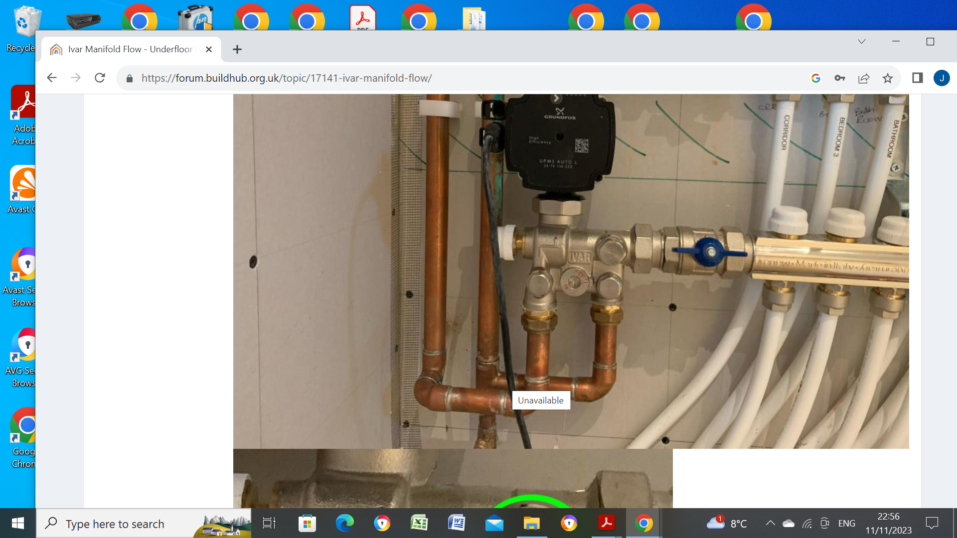
Looks like a very crude form of manifold temprtature control to me, normally, a TMV (mixing valve is used) which mixes some of the manifold return with the hot incoming boiler water to give the required manifold temperature, if its supplied from a ASHP at say 35/45C then neither a TMV or the above required. -
UFH: is my water temperature mixer working?
John Carroll replied to nickldn's topic in Underfloor Heating
Are you saying the pipe marked "flow"is the hot supply to the mixer?, thought that might be the manifold cold return to the boiler, if the flow is as shown then the Mot. valve is on the return?. -
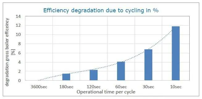
Cycling doesn't have a huge effect on efficiency, also you don't see too many complaining about the constant cycling with systems like Evohome which will still cycle a boiler even when the system demand is greater than the minimum (gas) boiler output.
-
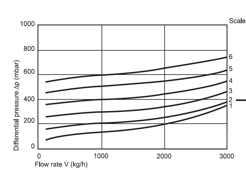
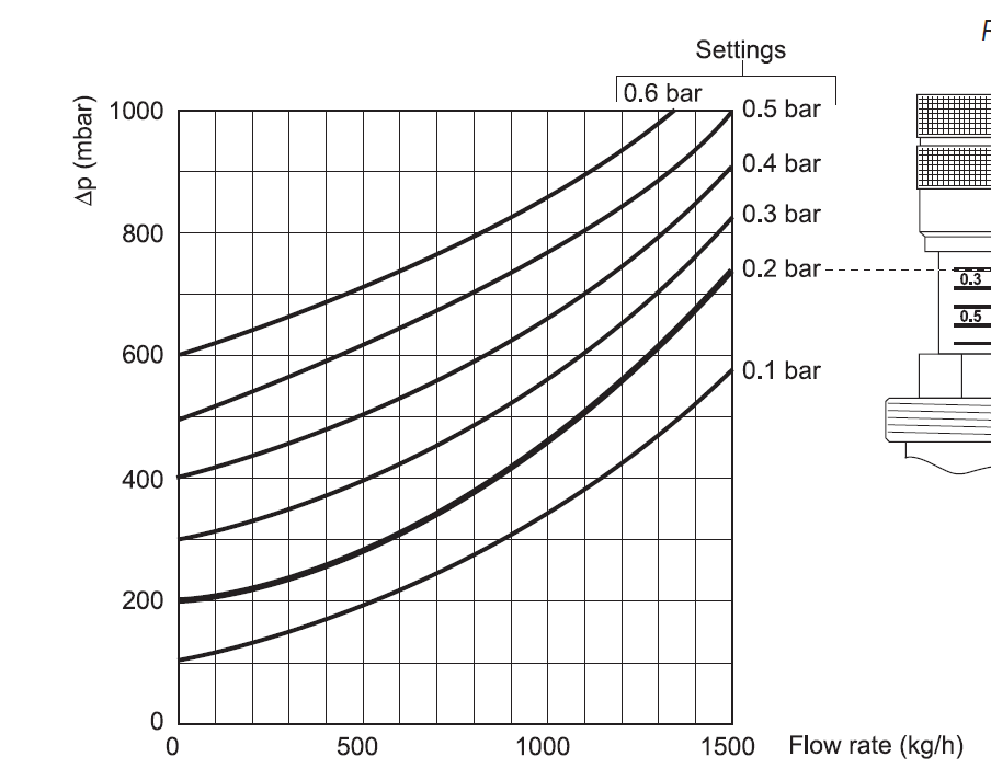
The DU144 gives excellent control over different by pass requirements especially where high pump heads are required. Even with pump heads of 6M or more a broad range are bypass flows are available, but the DU145 (angled type) has completely different flow characteristics (bottom flowchart) so basically useless with a high pump head requirement, ie pump head of 6M with ABV set to index 6 gives a minimum flowrate of ~ 800 LPH, 13.3LPM forcing the installation of a manual (throttling) by pass valve in line with this ABV if bypass requirements are less than this type of ABV, these characteristics seems true of all ABV manufacturers but I certainly wasn't aware of it until I read of someone posting on here who required a high bypass flow of > 14LPM, 840LPH using a 8M pump and I thought it was a faulty ABV as the straight type will provide this at a index setting of 6 (0.6) or less but I was looking at the wrong type of ABV, the DU144 instead of the installed DU145.
-
I would suggest that you fit isolating valves as AAVs are notorious for getting blocked, at least you can remove and clean them or replace them then.
-
CCTs, separation, bypass, and all that guff
John Carroll replied to HughF's topic in Underfloor Heating
If you are getting 3C dT then UFH output is ~1.1kw, have you a link to the mixing valve, it seems to have a adjustable bypass (if like the one below) there is only ~ 0.7LPM of hot water at 45C mixing with 4.3LPM of UFH return water at 23C so requires very tight control, you would require 1.0LPM mixing with 4.0LPM to get 33C mixed temperature.
-
CCTs, separation, bypass, and all that guff
John Carroll replied to HughF's topic in Underfloor Heating
A dT of 2C with a assumed total flow of 5.0LPM = UFH output of 0.7kw. -
CCTs, separation, bypass, and all that guff
John Carroll replied to HughF's topic in Underfloor Heating
Have you tried turning up the mixing valve setting until you achieve 33C, it should react fairly rapidly. -
CCTs, separation, bypass, and all that guff
John Carroll replied to HughF's topic in Underfloor Heating
What temperature is the HW (from the HP) going to the mixer?, if its 45C then it should give a mixed flow of 33C if the index on the TMV is accurate, once the slab is heated up then you might expect a return of 25C/27C, a dT of maybe 6C to 8C, if the flowmeters are flowing 2.5LPM each then the UFH input will be 2.1 to 2.8kw. -
CCTs, separation, bypass, and all that guff
John Carroll replied to HughF's topic in Underfloor Heating
What temperature are you running the UFH (flow) at and what total flow rate through the two loops and return temperature do you expect?. -
So, if it states on a stat that the differential is 0.5C does that differ from a stat that states its hysteresis is 0.5C or does it mean the same thing? it's interesting because I have a simple digital stat set to its lowest differential setting of 0.3C, as soon as the stat switches off, you then have to increase its SP by 0.3C to get it to switch in again, it will then switch off at its SP temperature but after a few cycles it will switch OFF/ON at SP +/-1.5C. Its FantiCosmi stat.
-
Are you sure the Wunda stat is working correctly? A setpoint temp of 22.0C with a switching differential of 0.5C should mean a switch on at 21.5C and switch off at 22C.
-
Could you please post the above with Tout extending to its max, say ~ 60/65C. Thanks. John
-
Plumbing in a Willis to UFH to dry screed - OK for beginners?
John Carroll replied to Tom's topic in Underfloor Heating
True, but generally the emitter would/should be matched however roughly to the expected heat loss, I think/hope the OP is only talking about the commissioning process, he is hardly going to oversize by a factor of ~ 5. -
Plumbing in a Willis to UFH to dry screed - OK for beginners?
John Carroll replied to Tom's topic in Underfloor Heating
You left hand manifold has 11 loops, at a dT of 8C and a flowrate of say 2.5LPM will output 15.3kw so the willis at 3kw will do OK for initial heat up/drying out especially since you can set it's thermostat but hasn't a hope of supplying the required UFH output when drying out or whatever when completed. -
Yes, but achieves exactly the same objective, to give you the required hot manifold UFH temperate, I know these controllers as tapstats. There is no loss of heat, you have a lower flowrate with a higher dT on the heat pump side and vice versa on the UFH side, both balance. The HP will run with reduced efficiency if its required temp of 48C is required elsewhere like for HW production but your floor covering dictates a max water temp of 36C.
-
Yes, it's the thermostatic mixing valve,TMV, generally contains a plastic piston/shuttle which can be removed.
-
Can you remove the shuttle, clean it up, apply a bit of silicone grease and see how it goes.
-
What way is the arrow on the manifold pump pointing, is it up or down?
-
What Boiler to prevent short cycling?
John Carroll replied to windsor-tg's topic in Central Heating (Radiators)
Oh yes, wait for @SimonD. When you were running on pump speed1 (6M) the boiler, just before cycling, had flow/return temps of 69/44, a dT of 25C, that boiler apparently has a minimum output of ~ 6.5kw so, by calculation, the flowrate is only, 6.5*860/60/25, 3.73LPM, which, with all those rads just doesn't add up except some big restriction somewhere, you then increased the pump head to 8M and no more cycling, the flowrate should have increased by just over 15% due to the increased head so it still looks as if the heat demand is quite low, maybe, when you get the opportunity, start with d.0 at 7kw, the boiler flow temp should then surely start falling and just increase d.0 (1kw steps) until the flow temp increases to its target temp of ~ 70C, this will then tell the flowrate almost exactly. (by calculation)