John Carroll
-
Posts
577 -
Joined
-
Last visited
-
Days Won
3
Everything posted by John Carroll
-
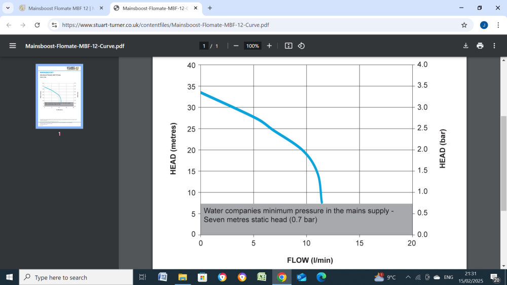
This is probably very similar to your pump, your pump has a higher closed valve head of 3.98bar. It should really have no problem in reaching a cut out SP of 3.0bar when the demand finishes, as long as the inlet pressure is > than 0.7bar. How long is it running for before it cuts out at 2.2bar? You might also measure the accumulator circumference with a tape, can then get a good idea of its capacity at 6ft? high.
-
A few basics about any accumulator. Its important that the precharge pressure (air end pressure with no pressure at the water end) is set to just slightly less than the minimum required pressure, if, for example, the minimum required pressure is 1.5bar, then the precharge pressure should be set to 1.3bar, if the pump SP pressure is set to its design? pressure of 3.0bar then the available water vol per 100L of accumulator capacity is 34.5L, if the precharge pressure, for whatever reason is set to only 0.5bar then the available water vol in falling from 3.0bar to 1.5bar is only 22.5L, important to bear this in mind. You have the pump SP at 2.2bar , assuming the precharge pressure is 1.3bar then the available water vol in falling from 2.2bar to 1.5bar is 28L (per 100L of accmulator vol), I would definitely suggest checking that precharge pressure and set it slightly below your required minimum pressure and reducing the diff to 0.8 bar, as you suggested, Can you also post the pump inlet and outlet pressures with a big demand. Also the the indexed setting in the window of that ABV?, automatic bypass valve, located between the two pressure gauges.
-
Unvented Expansion Vessel Pre Charge
John Carroll replied to Mattg4321's topic in Boilers & Hot Water Tanks
What is the continuous HW flow?, just run that same HW bath tap that gave you the "accumulated" 28LPM but don't take a flow reading for say 8 to 10 minutes, or until the flow dies down, to ensure no boosting from your EV. For interest a (mains only) accumulator filling pressure of 4bar and a "user" pressure of 3.0 bar will provide 20L per 100L in falling from 4.0bar to 3.0bar, other numbers, 4.0bar to 2.5bar = 30L. 3.5bar to 2.5bar = 22.2L. 3.5bar to 2.0bar = 33.3L. 3.0bar to 2.0bar = 25L. -
I reckon the boiler efficiency changes by ~ 4.5% for every 100C change in fluegas temperature.
-
OK, you will see from one of my previous posts that assuming the wet gas loss is 10% that this results in a condensate vol of 0.1595L/kWh of consumed gas,( "confirmed" more or less by @Bornagains calculation). From your data, gas consumption was, 544.539-544.019, 0.42m3, assuming 11.0kWh/m3, consumption was, 0.42*11.0, 4.62kWh, IF fully condensing, then condensate vol, 4.62*0.1595, 0.7369L, 0.7369*1000, 736.9g, actual condensate (collected), 612g, 612/736.9, 83.05%of max condensing, so condensing effect 10*0.8305, 8.31% (slightly higher than original calc), overall boiler efficiency, 88.8+8.31, 97.11%. "Meter reading at start 544.019 m3, Meter reading at end 544.439 m3. Condensate collected 612 grms"
-
But your boiler efficiency is still ~ 97% (as per graph, above), at say 30C fluegas temp, with a OAT of 4.1 C you are losing ~ ((30-4)/100)*4.5, 1.2% sensible heat to give 88.8% + the condensing effect, not quite the full 10% but by my calcs, 8.29%, to give a overall efficiency of, 88.8+8.29, 97.09%, TG it didn't come out at > 100%!!.
-
Ah well, this 79 yearold boy's chemistry isn't that far out so, I use 11.0kWh/m3 and condensate of 0.1595L/kWh = 0.42*11*0.1595*1000, 738g, only 3% or so higher than the above.
-
Gas consumption, 0.42*11.0, 4.62kWh, condensate, 612/1000. 0.612L, condensate vol, 0.612/4.62, 0.13225L/kWh, condensing%, 0.13225/0.1595, 82.92% (using my figure of 0.1595L/kWh if fully condensing) and possible higher and even approaching 100% if my figure is a bit high. CondensingBoilerEfficiencyGraph.bmp
-
Don't forget the gas meter readings, required to make any sort of calculation.
-
Unvented Expansion Vessel Pre Charge
John Carroll replied to Mattg4321's topic in Boilers & Hot Water Tanks
If you are happy with the continuous HW flowrate then the only other thing I would try is to reduce the PRV setting to ~ 1.5bar to 1.8bar. -
Unvented Expansion Vessel Pre Charge
John Carroll replied to Mattg4321's topic in Boilers & Hot Water Tanks
Thats a link to the EV, Matt, have you a link to the UVC?. -
Unvented Expansion Vessel Pre Charge
John Carroll replied to Mattg4321's topic in Boilers & Hot Water Tanks
Have you got a link to that UVC? The accumulator effect will give 10.8L after a full reheat and 6.75L each time after the hot flow is stopped, in falling to 1.5bar so its effect will only last a few minutes, at best. 28LPM seems a extraordinarly high flow rate, especially if continuous, so no worries re flowrates, I would just motor on as is with a 1.5bar precharge? -
Unvented Expansion Vessel Pre Charge
John Carroll replied to Mattg4321's topic in Boilers & Hot Water Tanks
You seem to have a Joule UVC, but not one with a internal bubble which they also manufacture. Is the inlet control group a Joule, it shows the EV connected to the inlet group although difficult to imagine why just teeing it in elsewhere should cause noise. I think its important to check that the control group has a check valve, if not Joule's. This bit is a bit confusing.......highlighted by me. EXPANSION VESSEL "The expansion vessel receives the increased water volume when expansion takes place as the system heats up and it maintains a positive pressure in the system. The expansion vessel contains a flexible diaphragm, which is initially charged on one side with nitrogen, but can be topped up with air when required. Select a suitable position for the expansion vessel. Mount it to the wall using the bracket provided and connect to the inlet control set with the flexible hose provided. Ensure that the top of the vessel is accessible for servicing. The pipe connecting the expansion vessel to the system should have a diameter of not less than 15mm and must not contain any restrictions. Prior to connecting the expansion vessel to the system the pipework should be flushed Joule Cyclone Installation Instructions.pdf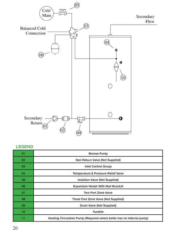
-
You should use the exponential 1.3, thats why they speak of weather compensation curves even though heat loss is linear but rad output isn't. So its (39/50)^1.3 = 0.724 and (44/50)^1.3 = 0.847 not hugely different to the above but does become significent at low rad mean temps.
-
Unvented Expansion Vessel Pre Charge
John Carroll replied to Mattg4321's topic in Boilers & Hot Water Tanks
I thought these control groups would consist of a pressure reducing valve, a pressure relief valve and a check valve, with the check valve after the PRV but before the expansion relief valve. Isn't a NRV installed somewhere mandatory with UVCs?. If there is no ckeck/NRV then maybe thats a possible cause of noisy operation with the EV precharge of 2.5bar or even lower as the water can expand back through the balanced cold, I would check out that installed control group. So, what does all this mean now??, are we saying that a UVC cannot operate properly at a dynamic pressure of 1.5 to 2bar, I think it certainly should if the user is happy with the flowrate, upgrading the supply may or may not fix the problem. I would think that if the EV is precharged to 1.5bar (which it is) and the PRV setting reduced to 1.8 to 2.0 bar (from 3.0bar, if adjustable) then there is no excuse for noisy operation IMO. Have a word with Teleford? or whoever the UVC manufacturer is. -
Unvented Expansion Vessel Pre Charge
John Carroll replied to Mattg4321's topic in Boilers & Hot Water Tanks
To avoid any confusion, it should be teed in somewhere between the valve set and the UVC cold water inlet, I call(ed) this downstream, which I think @Mattg4321 has confirmed, in other words, correctly, whatever about ideally. -
Unvented Expansion Vessel Pre Charge
John Carroll replied to Mattg4321's topic in Boilers & Hot Water Tanks
Is the EV just teed in somewhere down stream of the valve set on the cold supply to the cylinder? -
Unvented Expansion Vessel Pre Charge
John Carroll replied to Mattg4321's topic in Boilers & Hot Water Tanks
Is your system plumbed up like this?.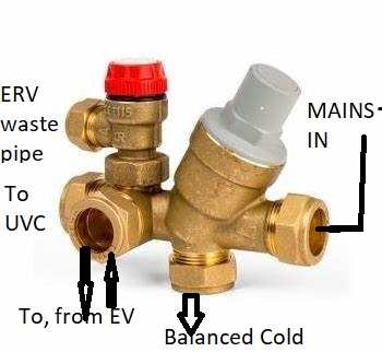
-
Unvented Expansion Vessel Pre Charge
John Carroll replied to Mattg4321's topic in Boilers & Hot Water Tanks
Is the whole installation only a week old?, what did it replace. Since the dynamic pressure is ~ 2.0bar, then maybe reduce the PRV setting to this value, there are plenty of systems I would think set up like this, where the PRV is set to or slightly above the dynamic pressure. Can you post a few photos of the system, combination valve set with PRV, expansion relief valve, balanced cold take off etc and the EV showing exactly where its teed into the combination valve set etc and pipework. -
Unvented Expansion Vessel Pre Charge
John Carroll replied to Mattg4321's topic in Boilers & Hot Water Tanks
Strange allright, it seems the accumulator effect is helping even though the EV diaphragm will be moving far more at a precharge of 1.5bar vs 2.5bar. At 1.5bar precharge and after a full reheat the EV will flow 10.8L into the system with a big demand for HW and subsequently 6.75L will flow back in when the HW stops but will flow that 6.75L back out when the HW is again drawn off strongly, at 2.5bar precharge those numbers become 6.3L, and 0.9L., the only thing I can think of is that with the low precharge pressure of 1.5bar then the diaphragh will rarely if ever bottom out but will bottom out continuously with a 2.5bar precharge. Hate to be throwing new bits in the hope of fixing things but mabe a new EV plus a new PRV in case its leaking past might cure the problem but no guarantee that it will. -
Unvented Expansion Vessel Pre Charge
John Carroll replied to Mattg4321's topic in Boilers & Hot Water Tanks
No, can you do the same test on the UVC only, also you wouldn't want to be setting that precharge pressure too low, you can see from the attached, (do your own calcs, never mind that acceptance factor) that the lower the precharge pressure, the higher the final pressure which may cause that noise and/ or lift the expansion relief valve, what setting is it at?, it should be either 6.0bar or maybe as high as 8.0bar, its written on the end of it. If the UVC test gave you say 16.0LPM would you be happy enough with that, apart from the noise?. Expansion Vessel Calculation Rev 0.xlsx -
Unvented Expansion Vessel Pre Charge
John Carroll replied to Mattg4321's topic in Boilers & Hot Water Tanks
OK, assume a worst case of 12.5mm ID for of 15M of pipe, this gives a dP of 0.92bar @ 18.0LPM & a dP of 0.52bar @ 18.0LPM through 12M of 13.6mm ID pipe, 0.92+0.52, 1.44bar, add 20% for fittings etc, gives a total of, 1.44*1.2, 1.73bar?? -
Unvented Expansion Vessel Pre Charge
John Carroll replied to Mattg4321's topic in Boilers & Hot Water Tanks
The flowrate is 18.0LPM at a dP of 3.6-1.4, 2.2bar, 15M of 15mm ID pipe has a dP of 0.38bar at 18.0LPM, 15M of 11mm ID pipe has a dP of 1.72bar at 18.0LPM, so either you have a partial restriction in the (IF) 15mm piping or the ID is "only" 11mm or very close to that. Can you do that dynamic test with a hot water tap only (say the bath HOT tap) to see whats what with the UVC?. The acceptance volume is really only the (EV) airend vol/total Vol, easily determined from the precharge pressure and the final pressure, both absolute, say precharge pressure is 2.0bar = (2.0+1.0), 3.0bar.abs anf final pressure is 3.0bar =(3.0+1.0),4.0bar.abs, then the acceptance factor is (1-(3.0/4.0))*100, 25% and so on, sometime, post the UVC & the EV volumes and we can do a few calcs, I have a ancient but very easily understood spreadsheet that I built decades, will post later. -
Unvented Expansion Vessel Pre Charge
John Carroll replied to Mattg4321's topic in Boilers & Hot Water Tanks
What was the flowrate when you tested the dynamic pressure??, I have a bit of 21mm OD, 11.0mm ID piping lying around here since this house was built 53 years ago, so IF the ID of your pipework is only 11.0mm then 15M at a dP of say 4.0-1.0, 3.0bar will still flow 23LPM, it will still flow 13.5LPM at a dP of only 1.0bar, if your pipework is 15mm ID then it will flow 55LPM at a dP of 3.0bar and 31LPM at a 1.0bar dP., so its important that you know what the flowrate (& dP) was during that dynamic test before you go off doing anything. -
Unvented Expansion Vessel Pre Charge
John Carroll replied to Mattg4321's topic in Boilers & Hot Water Tanks
Maybe we're all barking up the wrong tree!, if these friction loss calculators are to be believed, then 15M of 15mm ID pipe should only lose < 1.0bar at a flowrate of 30LPM, maybe check out the PRV for faulty operation or filter blockage?. You are getting a dP of ~ 2bar at probably around 15/20LPM?. https://www.omnicalculator.com/physics/friction-loss