John Carroll
-
Posts
577 -
Joined
-
Last visited
-
Days Won
3
Everything posted by John Carroll
-
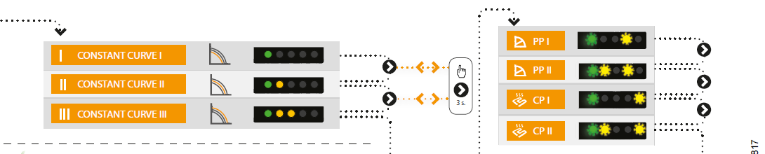
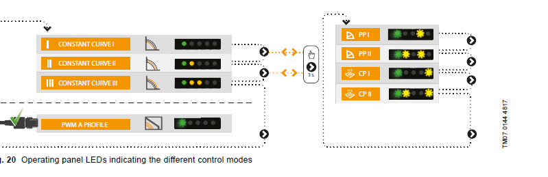
By running the UPS3 at its lowest setting PP1 then if you are stlll getting pump over, you have a serious blockage problem, a few other thoughts, those UPS3s have a very poor reputation around here, I know several people who will not install them but I would be a bit surprised if it wasn't running properly in its requested mode. That 50W model of 5M Selectric is one of the lowest head pumps so wouldl expect little or no pump over with it. Are you absolutely sure that there isn't a circ pump in the boiler and that is being boosted by the UPS3 . Anyhow try PP1, if still pumping over then problems. Can you post a photo of the pump LEDs when running in CC1 just now and also when/if running in PP1. Also check both isolating vaves on pump fully open.
-
I would advise to get a plumber (not a salesman) to cut out that H and inspect/clean it out/renew it., If the original pump was a Selectric (a pretty low head pump) then the clean out of the system + the installation of the UPS3 might have started that pump over, you can try and establish the blockage by trying that PP2 setting or, if still pump over, try PP1 even though that will almost definitely not satisfy your circulation requirements but will give some idea of the state of affairs.
-
Right, if possible, before your plumber arrives tomorrow??. Just to be sure to be sure, check that the pump is on CC1 as shown by the one green LED. Then change to PP2, as shown by the combination of flashing LEDs on the right, see if you've still got pump over.

-
The plot thickens but first this pump over conundrum. Expansion effect first, a system with 100L of water and a average flow/return temp of 60C will expand by 1.62%, so 1.62L, this will increase the level in the F&E cistern and in the vent by equal amounts (since its a U tube) so ~ 10 to 15mm as 99% of the expanded volume is taken up by the F&E cistern (well named) but the U tube effect means the level in the vent pipe will rise by the same amount even though the vol of water is tiny. With a perfectly clean system there will still be a very very slight pressure loss in that short piece of pipe in the H as the full circulating flow passes through it, if, for any reason a restriction start building up in that pipe then the U tube starts to become unlalanced with the level in the vent rising and the level in the cold feed falling, eventually, if the restriction becomes very bad, the water will reach the top of the vent and start "filling" the F&E cistern, and water will start flowing down the cold feed. Re UPS pump settings, this is very strange, on CC1 the pump head (4.2M) will be greater than 3.0M (CP1 constant setting) until the flow rate reaches 1.3m3/hr, 21.7LPM, and will not fall below 3.0M until the flowrate is 1.4m3/hr, 23.3LPM so there is no logical reason for this behaviour IMO. However, that as it may, one could fill a small book with pump over problems just because the circ pump was changed, As I said previously a few have changed to my 52 year old system exactly as it is, see below, problems disappeared even though there were no blockages apparent in the H.
VentColdFeed.JPG.7d22bc40a153562aa4c3450bcac23307.JPG)
-
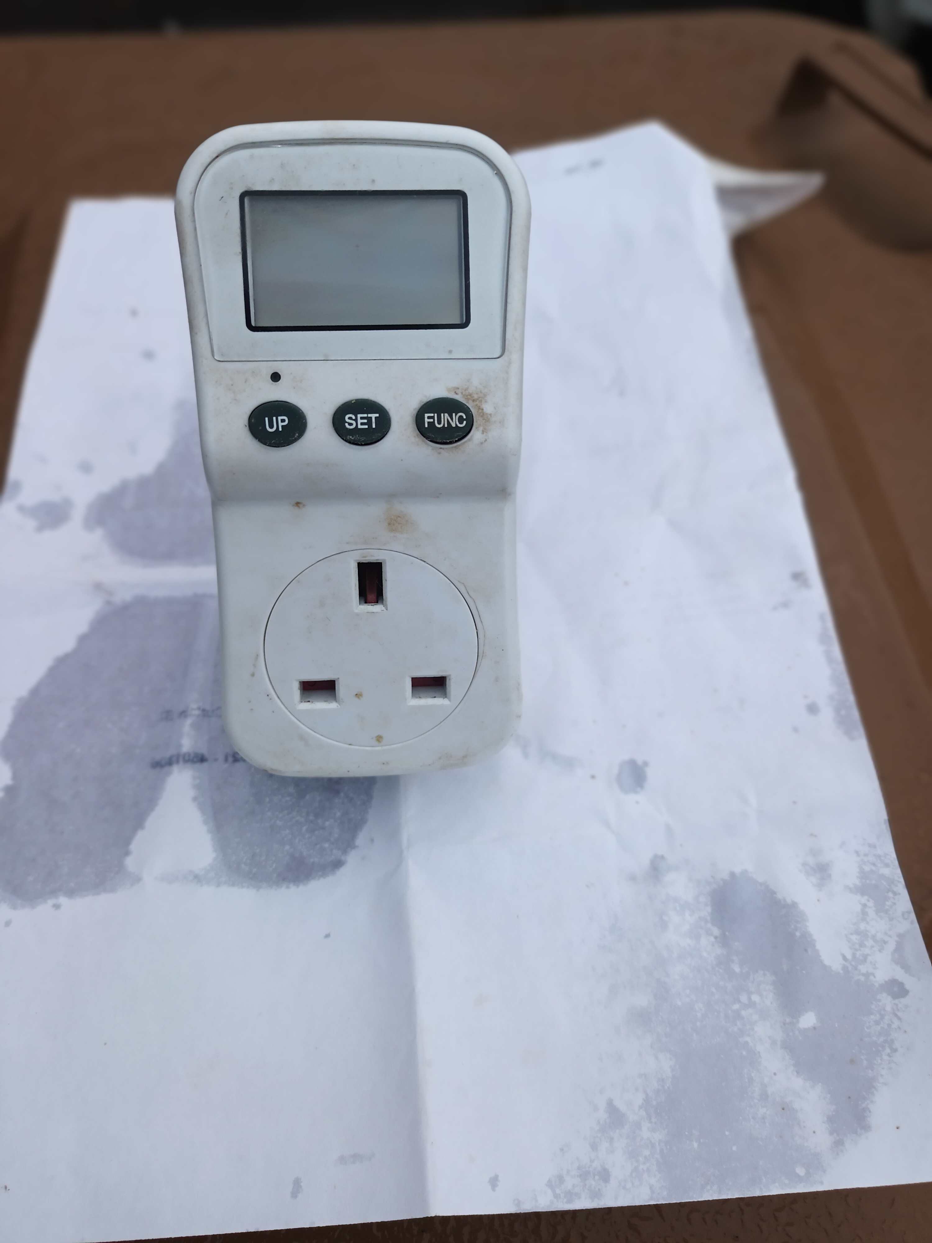
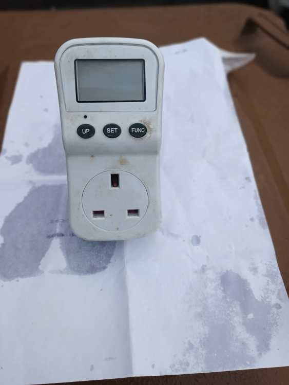
Its a pity that the UPS3 doesn't at least display the pump power in watts, W, from which the flowrate that then easily be read off from the pump cuves, most A rated pumps now not only display this but display the flowrate as well in m3/hr, very useful for trouble shooting, however, a plug in energy monitor which are very accurate can be bought for £15/£20, the pump cable is removed from its JB after noting the ter. numbers/locations, a short length of cable with a socket is then connected to these ter. points, the energy monitor is plugged into the socket, a 3 pin plug is attached to the pump cable and plugged into the energy monitor, I installed one of these a long time ago for someone and its still permanently monitoring the pump power.
-
It still doesn't change that "6mm" restriction calculation, have you any idea or can you measure the distance from the F&E cistern water level to the the "crook" in the vent where its turned down into the cistern.
-
The system you have is well known, where, from the boiler, you have the Vent, then (no more than 150mm away) the Cold feed, then the Pump, VCP. Your system seems to have 25MM piping at the H where the cold feed is teed in, if so then if you assume a flowrate of 15LPM, it would take a restriction (in the short piece of pipe, say 125mm), between the Vent and Cold feed) corresponding to ~ 6mm piping to cause a imbalance of 2M between the vent and would seem very unlikely as the flowrate would then be restriced as well, but you just don't know without cutting out that whole H to check. I have seen pump over in systems with perfectly clear Hs, this can sometimes be cured by shifting the cold feed up say 100/150mm and teeing it in to the vent (and capping the top of the left top of the H, to give a combined vent and cold feed.
-
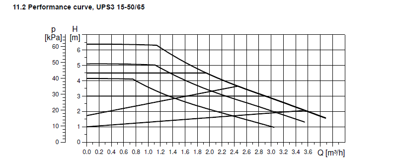
No, any (developed) pump head is the difference between the discharge pressure and the suction pressure, the discharge pressure will depend on where the cold feed (or expansion vessel in a sealed system) is teed in, your cold feed is teed in just before the pump so assuming no blockages between there and the pump, then the pump inlet or suction head will be the height of the F&E cistern water level above the punp, so if the water level is say 2M above the pump then the pump inlet pressure will be 2M but the pump discharge pressure will be the developed pump head + 2M, so on CC1 will be 4.2+2, 6.2M, on CC2 will be 5.2+2, 7.2M & on CC3 will be 6.4+2, 8.4M, any restriction will not change the conditions at the pump, if, for example you shut the pump discharge valve, (full restriction) the pump inlet and discharge pressures will not change, the pump speed will just ramp down to give its set (developed) pressure.
-
Cheap way to prevent boiler cycling
John Carroll replied to Crunchynut's topic in Boilers & Hot Water Tanks
Don't know what your boiler outut is, but based on 26kw then a 50sec off time means (assuming a stat hysteresis like mine of 10C) a average heating demand of 17.6kw. I did a few calcs some time ago for someone who was considering installing a buffer, (he didn't), you might find the attached interesting, you can stick in your own numbers. Also attached is the effect of cycle times on boiler efficiency, its not a awful lot except you have a hughly overrated boiler. Oil Fired Boiler Cycle Times SD Rev0.xlsx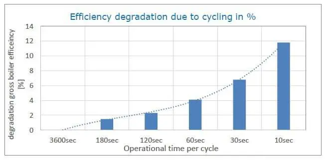
-
Ok, then one pump, the UPS 3 on speed 1 at 4.2M shouldn't really cause pumpover with a clean system but running at 3.0M certainly shouldn't so give it a go, it might still give sufficient circulation.
-
You say you have a regular boiler which is sometines called a heat only boiler which has no internal pump so you would have a external pump like the UPS, you also say "The pumps are both pumping downwards", have you got another pump close to the boiler?,
-
You say that the UPS pump inlet is from the boiler flow?, or is it from a LLH (low loss header) for the CH only, where the boiler pump is pumping into the header, the UPS is then circulating some or all of this water through the rads with their returns going back into the header, then to the boiler return?
-
There could be a restriction where the cold feed tees into the Vent even though you are getting "recirculation", also the UPS3 is a giant of a 6.4M pump and even on fixed speed1 will still have a 4.2M head, as much if not more than the normal 6M pumps give at full speed. You could change to constant pressure CP1 at 3.0M and see how it performs, 3 to3.5M is normally fine for most domestic systems and it may stop the pump over as it will running at over a meter lower head.
-
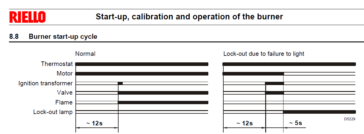
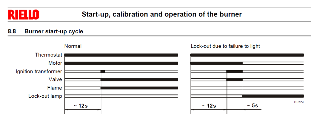
Friend had a few problems with the above not firing up so I took a few readings off my own nearly 20 year old Firebird with the same burner and control box. The oil solenoid coil is a 3 wire with two windings, one is 1.4 ohm (start up), the other is 1400 ohms (holding). What is supposed to happen is, 12 secs after the prepurge, both windings get 30VDC, after the 30V drops off the start up winding and 3V is supplied to the holding winding and the 30V is removed. But, on mine, 30V (actually 27V) is supplied to both windings from the runup start. After ~ 17 secs the 27V is removed from the holding winding, leaving 3V (actually 4.5V), but I still measure 27VDC on the start up (1.4 ohm) winding which apparently remains there while the burner is firing. If so then one would expect the coil to burn out very rapidly?. I also removed the burner from the boiler and placed it on the ground and started/stopped it 4 times after 9 secs but before ignition point so ~ 36secs but couldn't see any signs of oil dribble which would surely be apparent if the oil valve was energised at the start of runup. There is normally ~ 5bar pressure on runup & before the oil valve is energized CLOSED , the oil pressure then builds up to ist's normal 8bar and fires the burner. Any thoughts on this?.
-
I have a 6M Wilo Yonos Pico, which, apart from the traditional 3 speed settings, also has CP (constant pressure and PP (proportional pressure) modes, both of which can be incrementally changed in 0.1M steps to give any required head, this pump also displays (like the DAB Evosta 3), the pump flowrate in m3/hr and the power in watts
-
Can someone explain or throw some light on the above, this boiler's hydraulic settings can be set to several modes, constant speed, dp constant pressure (between 100mbar & 400mbar) and dT Temperature Spread (between 10C & 20C). This boiler is having problems in running in either dP or dT modes so is running in constant speed mode until problems resolved. The EcoTec 430 gives the actual HEX pressure loss so relatively easy to calculate the Residual Head with any known circ pump, I have done a few calcs based on using a 6M (Wilo) pump. The EcoTec 630 does not give this very useful info, nor do they give the boiler's installed pump head, it does give a "Pump Curve" (see attached) which shows flow rates of 25.8LPM @ 100mbar head, 23.0LPM @ 200mbar and 19.0LPM @ 400mbar which makes no sense to me as the flowrate is apparently decreasing with increased pump head, hence the query. The boiler comes in default dP mode, set to 200mbar. The D parameters showed (actual) flowrates of 11.65LPM @ 50% pump speed, 20.6LPM @ 80% and 25.47LPM @ 100%. This boiler has a Vaillant LLH installed. Residual Pump Head Extract Rev0.xlsx
-
Water flowing back into the grid during a mains fail
John Carroll replied to puntloos's topic in General Plumbing
The available volume for any accumulator is (1-((prechargepressure+1)/(chargingpressure+1)) X accumulator volume) For example, in a nonpumped accumulator, if 1.0bar is sufficient for your needs then a 200L accumulator will be precharged to 1.0bar, and assuming a fully charged accumulator from mains at 3.0bar, then the available volume on mains failure is 1-(1+1)/(3+1) X 200, equals 0.5*200, 100L A pumped accumulator like yours, assuming you require a minimum pressure of say 2.0bar would be precharged to 2.0bar and assuming the pumped charging pressure is 4.0bar, then the available volume is, 1-(2+1)/(4+1) X 200, equals 0.4*200, 80L. but remember then, because the diaphragm will now have bottomed out that you you won't get a single drop of any extra water even if 0.5bar is enough in a emergency. -
I thought I replied to this, anyway, That pump setting of proportional pressure PP1 is not suitable, apart from being far too low, for UFH, suggest setting to constant pressure CP2, (LED on far right, no4), this is a constant pressure of 3.0M, then set your flowmwters to 2 to 2.5 LPM and see how it goes.
-
Vaillant EcoTec Plus 630 dT
John Carroll replied to John Carroll's topic in Boilers & Hot Water Tanks
Yes John, The fixed speed is settable, 50% to 100%, and a few tests showed a (vaillant) flowrate of (converted from LPH) 24.3LPM at 100%,and 11.53LPM at 50% which makes good sense, since flow is directly proportional to speed. The dT tests did nothing, there is also a constant pressure option, settable between 100mbar and 400mbar but the tests were inconclusive as 400mbar gave ~ 23LPM but 150mbar didn't produce a much lower flowrate whereas it should theoretically, have been, 23*sqroot (150/400), 14.1LPM. -
Vaillant EcoTec Plus 630 dT
John Carroll replied to John Carroll's topic in Boilers & Hot Water Tanks
The rads flow/return are 60C/50C, mean of 55C, so a, (55-20), T35 Rad, which will emit (35/50)^1.3, 63% of a T50 rating, irrespective of what is going on elsewhere, you then have ( UFH), 3.84LPM@32C mixing with (rads), 5.73LPM@50C to give 9.57LPM@42.8C goint to LLH secondary but because the boiler circ pump is circulating 21LPM then the primary side recirculation of 11.43LPM@60C is mixing with that returning 9.57LPM@42.8C, you end up with a boiler return of 21LPM@52.2C. As you allude to, a LLH can becomes a DLH, (Dead Loss Header?) unless the primary and secondary flows are equal., hence the desire to get that dT control working, I have read of other conventional installations (no LLH) where that boiler doesn't achieve this either. -
Vaillant EcoTec Plus 630 dT
John Carroll replied to John Carroll's topic in Boilers & Hot Water Tanks
This is what someone is trying to do (if Vaillant can sort out this dT control problem). There is a rad(s) demand of 4kw and a UFH demand of 7.5kw, a boiler flow temp of 60C is required to give the required rad output, this means the boiler return is 52.2C, 7.8dT, not too bad, but just about condensing, this is with a boiler circ pump flowrate of 21LPM, if the boiler dT was increased to 16.5C, then the boiler return temp should be ~ 43.5C with quite considerable condensing, this is with a boiler circ pump flowrate of 11.5LPM, if my calcs, attached, are correct. LLH + Rads and UFH Rev0.xlsx -
Don't know if new cylinder is installed but just for interest, OSO technical inform that its cylinders do not have a baffle so removing the dip tube and installing a EV to give that ~ extra 20/25% extra capacity does not leave something to bang about inside.
-
What is the ufh demand in kw, how many loops?. Coil rating is often based on a flow temperature of 80C and maybe 30/35 LPM flowrates so ensure both coils are suitably rated.
-
Noisy Radiators... we have an ASHP
John Carroll replied to sirpatchuk's topic in Other Heating Systems
Looking at the OAP's pump it seems to have just 3 speeds so should be just a case of pressing the setting button (arrow) and try speed I, first check and see if its running at setting III. -
Noisy Radiators... we have an ASHP
John Carroll replied to sirpatchuk's topic in Other Heating Systems
That makes sense, I think those settings are 4M,5M,6M&7M, so try the 4 or 5m curve.